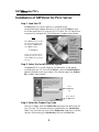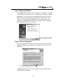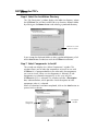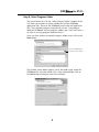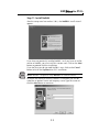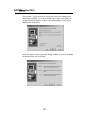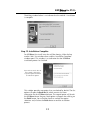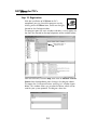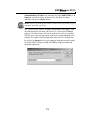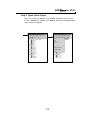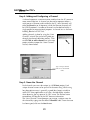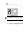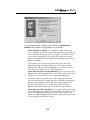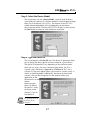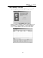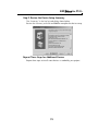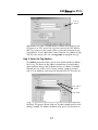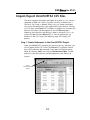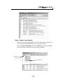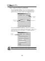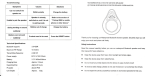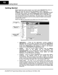
1
Direct for PLCs
KEPD
Introduction
The purpose of this supplementary Manual
This KEPDirect for PLCs Setup manual provides the basics to install
the PLC server software; however, complete setup and operational
details are found in the KEPDirect for PLCs Help file once the software
has been installed.
Exercise caution: This manual is not intended to replace the online Help
documentation. This is intended only as a supplement, therefore, use it
only as a quick start guide.
Who can and should use KEPDirect?
If you have a PLC belonging to the DirectLOGIC PLC family, you can
use KEPDirect to connect your PLCs with your favorite Windows
client. The families of PLCs (DL05, DL06, DL105, DL205, DL305 and
DL405) can be connected to your favorite Windows client software.
This means that KEPDirect has the following capabilities:
• Connect your favorite HMI/SCADA software to low-cost
AutomationDirect DirectLOGIC PLC systems over a serial or a
10Mbit Ethernet network.
• Design a low-cost data acquisition/monitoring system using
affordable AutomationDirect PLCs. This means that any
industrial HMI/SCADA, data historian, MES or ERP software
package that includes an OPC client driver can connect directly
to DirectLOGIC PLC serial or Ethernet ports.
• Interface custom VisualBASIC or Visual C++ applications to
AutomationDirect PLC systems and eliminate time-consuming
driver development.
1
Direct for PLCs
KEPD
Diagram Showing the Basic System Compatibility
2
Direct for PLCs
KEPD
Preparing for Installation
Getting to Know Windows
KEPDirect software runs under 32-bit Windows operating systems
(98/2000/NT/XP). If you are more accustomed to using 3.1, please
take a moment to study your PC’s reference manual on the operation
of Windows (98/2000/NT/XP).
Check your PC Hardware Requirements
Please check the following requirements when choosing your PC
configuration.
Minimum System Requirements
• Windows 98
• Pentium 200MHz (or higher)
• 32Mb RAM
• 10Mb available disk space
• MS Internet Explorer 5.0 or newer
Recommended System
• Windows NT 4.0 SP5 or later,
Windows 2000, XP
• Pentium 400 MHz
• 64 Mb RAM
• 10Mb hard disk space
• MS Internet Explorer 5.0 or newer
NOTE: The server is designed to run on Windows 98, NT 4.0, and all
versions of Windows 2000 and XP. Some of the older Win 98 PC’s will
probably not have the Microsoft DCOM patch loaded since DCOM is not
native to them.
3
Direct for PLCs
KEPD
Surge Protection
It is highly recommended that the computer KEPDirect operates on has
some form of power surge protection. A quality surge protector will
protect your computer from most surges and spikes; however, an
uninterruptible power supply (UPS) will provide the ultimate
protection. A UPS provides isolation between the AC power source and
the computer and has battery backup for blackout and brownout
conditions.
Review Package Contents
Now is the time to review the contents of your KEPDirect software
package. You should have the following items:
• CD ROM
• Installation and Setup Manual
• Installation Key Code and Registration Key Code
4
Direct for PLCs
KEPD
Supported Devices
The DL05, DL105, DL06, DL205, DL305 and DL405 PLCs support
RS232-C and RS422 (may require an RS422 adapter) serial. The DL05,
DL06, DL205 and DL405 PLCs also support 10Base-T and 10Base-FL
Ethernet interfaces. Below is a list of supported devices:
• DL05 and DL06 PLCx: Supports the H0-ECOM, Ethernet
Communications Module.
• DL205 PLCs: Supports the D2-DCM , Data Communications
Module (serial), H2-ECOM, Ethernet Communications Module
and H2-ECOM-F, Ethernet Communications Module (fiber optic)
• DL305 PLCs: The DL330 and DL340 supports the D3-232-DCU
and the D3-422-DCU. The D3-350 (only), supports the D3-DCM,
Data Communications Module (serial).
• DL405 PLCs: Support the D4-DCM, Data Communication
Module (serial), H4-ECOM, Ethernet Communications Module
and H4-ECOM-F, Ethernet Communications Module (fiber optic).
5
Direct for PLCs
KEPD
Installation of KEPDirect for PLCs Server
Step 1: Load the CD
KEPDirect for PLCs Server Software is available on the
AutomationDirect Product Showcase CD. To install KEPDirect, insert
the AutomationDirect CD into your PC’s CD drive. The CD should start
automatically and open the “Install Software” window shown below.
Note:
If the DirectSOFT32 CD does
not start automatically, go to
the Windows START button,
select RUN and type:
E:\startup.exe
Change the letter E above to
match your CD drive. Then
click on OK and the program
will start.
Step 2: Select the Install Software Option
The DirectSOFT32 “Install Software” window offers all the options
available with this CD. To install KEPDirect, select the Install Software
option indicated on the figure above. This selection opens the Product
Key window shown below.
Enter
Product Key
here
Then click on
the OK button
Step 3: Enter the Product Key Code
From this window, enter the Product Key located on the back cover of
your CD case. This software package is protected by this Product Key
code. Only licensed users that have a Product Key code may install the
software. After entering the Product Key click on the OK button.
6
Direct for PLCs
KEPD
Step 4: Welcome Window
The KEPDirect install wizard starts and opens the “Welcome” window
shown below. This window issues a reminder to exit all other Window
applications. If you are unsure of the programs that may be running,
open the Task Manager by pressing the Ctrl-ALT-Delete keys at the
same time. Close any opened applications by selecting them and
clicking on the Close button of the Task Manager. Click on the Next
button to proceed with the installation.
Click here to proceed with
the KEPDirect installation
Step 5: License Agreement
The wizard displays the “Software License Agreement” shown below.
Read the agreement and select Yes if you agree with the terms and
conditions.
If you agree with the License Agreement’s
terms and conditions, click here.
The Back button returns you to the Welcome window. Selecting No
will cancel the installation.
7
Direct for PLCs
KEPD
Step 6: Select the Installation Directory
The “File Destination” window displays the folder (or directory) where
the KEPDirect files will be installed. You may choose a different folder
by clicking on the Browse button and selecting a preferred directory.
Click here to select
a different folder
If you accept the displayed folder or select a preferred directory, click
on the Next button to continue with the KEPDirect installation.
Step 7: Select Components to Install
The wizard now displays the “Select Components” window. This
window allows you to select the components to install for use with
KEPDirect. It is recommended that you select only the components
you want to install. When a main component is selected, all subcomponents are selected automatically. In this case, only the
KEPDirect for PLCs is selected. This window includes a Description
box, indicated below, which provides a brief description of each
component when it is selected.
When all selections have been completed, click on the Next button to
proceed with installation.
Description
window
Select main
component
8
Direct for PLCs
KEPD
Step 8: Select Program Folder
The wizard continues with the “Select Program Folder” window which
will allow you to select or create a folder to install the KEPDirect
application files. These are the KEPDirect launch help and application
files. The installation program automatically creates a new program
folder for KEPDirect. You may keep this folder, type a new name over it
or select an existing program folder on the list.
Once you have chosen or entered a program folder name, click on the
Next button.
Use the default name
or create a new name
The window shown below appears. Verify the folder name where the
KEPDirect files are to be stored. If this is the selected folder, click on
the Next button to continue with the installation.
9
Direct for PLCs
KEPD
Step 9: Start Copying Files
The wizard now displays the “Start Copying Files” window shown
below and displays the installation information as configured through
all previous steps. Verify that the installation information is correct. If
incorrect, click on the Back button to return to previous windows. If
correct, click on the Next button to start copying the KEPDirect files
to your PC’s hard drive.
Displays the installation
information configured
during the previous
installation steps
Step 10: KEPDirect Files Installation
The installation “Setup Status” window opens and displays the
progress of the installation and setup of the KEPDirect files. A progress
bar is displayed and a number indicating the percentage of the
process completed is shown next to the progress bar.
Progress bar and
Percentage completed
10
Direct for PLCs
KEPD
Step 11: Install NetEdit
After the setup status bar reaches 100%, the NetEdit 3 install wizard
appears.
If you have not previously installed NetEdit 3 or if you have an earlier
version of NetEdit, you can install this version now. Click on the Next
button to proceed with the installation.
If you feel that you do not need NetEdit 3 now, click on the Cancel
button to finish the KepDirect for PLCs installation.
NOTE: NetEdit3 is required to setup DirectLOGIC Ethernet devices.
For those who continue with the NetEdit 3 installation you will be
asked for an optional name and company name. Type the names or
click the Next button to continue.
11
Direct for PLCs
KEPD
The NetEdit 3 install wizard will ask for the name of the destination
folder where NetEdit 3 is to be installed. Either chose a file folder or
accept the default folder as shown in the dialog below. Click on the
Next button to continue.
Select the type of setup in the next dialog window, then click on Next
to continue with the installation.
12
Direct for PLCs
KEPD
The dialog window below is an indicator that the NetEdit 3 installation
is complete.
Step 12: Installation Complete
For KEPDirect, the install status bar will be showing. When the bar
reaches 100%, the window closes and the “Installation Complete”
window opens. This window is an indication that the KEPDirect
installation process has finished.
If you wish to cancel either of
these options, click on the
respective option checkmark
to uncheck the option.
This window provides two options that are checked by default. The first
option will open the Read Me file which contains the latest
information for the KEPDirect Software. The second option will launch
the KEPDirect Server Program. Both options will open after clicking on
the Finish button. You can either check or uncheck the option
selections and, click on the Finish button to end the installation
process.
13
Direct for PLCs
KEPD
Step 12: Registration
With the installation of KEPDirect for PLCs
completed, you may launch the program now by
clicking on the KEPDirect icon, shown on the right,
located on the Desktop window.
The program opens the main window and offers a set of options on
the menu bar located on the top left portion of the window below.
Click on Purchase a
Driver License
From the menu bar, click on Help, then click on Purchase a Driver
License from the drop down menu shown in the diagram above.
This opens the “Unlicensed Drivers and Plug-ins” window shown
below. This window allows you to select the driver which will be
used for your system protocal. The diagram shows the
14
Direct for PLCs
KEPD
AutomationDirect ECOM driver selected, but either DIRECT-NET or K
Sequence could have been selected. Once the driver has been
selected, click on the License button.
NOTE: You must go through the Purchase Driver License procedure for each
individual driver that you install.
The “ECOM Driver License” window, shown below, now opens. Find
the label located on the back side of the CD case for the KEPDirect
program. This label shows the license code for the software included
with the case. Enter the registration code on the space provided in the
window. This code can be entered either from your PC’s keyboard or
by clicking on Keypad and using the pop-up keypad to enter the code.
Once the code has been entered, click OK to accept the code and
complete registration.
15
Direct for PLCs
KEPD
KEPDirect for PLCs Server Setup
Summary
KEPDirect for PLCs Server is a software driver that provides a means of
communication between other software (OPC clients) and
components. In other words, KEPDirect is a translator server that
provides the communication bridge between the software (OPC clients)
and components.
OPC (OLE for Process and Control) servers provide a standardized
method of allowing multiple industrial applications to share data in a
quick and robust manner. The OPC server and LinkMaster products
provided in this package have been designed to meet the demanding
requirements found in the industrial environment.
This OPC server has been designed as a two-part program. The primary
component provides all of the OPC and DDE connectivity as well as
the user interface functions. The second part is comprised of plug-in
communications drivers. This two-part design allows you to add
multiple communications options to your SCADA application while
utilizing a single OPC server product thus reducing your learning curve
as your project grows.
LinkMaster has the capabilities of both a server and a client
application, allowing it to access, collect, organize, and link data from
other OPC servers and offer that data to any OPC/DDE client. It
provides the means of linking data between OPC servers; thus, acting
as a universal bridge for OPC server/client components.
OPC technology reflects the move from closed proprietary solutions to
open architectures that provide more cost-effective solutions based on
established standards.
16
Direct for PLCs
KEPD
Start a New Project
Step 1: Things to check
Before starting a new project, be sure that KEPDirect for PLCs Server has
been properly installed. Also, any devices to be added to your project must
be installed with modules in place, powered up and working properly.
For ECOM (Ethernet)
If you have selected the ECOM Driver License, you must provide the
proper IP addresses for each device that will be used in your project. You
can use NetEdit 3 to setup the ECOM module if needed. The IP
addresses will be required during the project setup in order to ensure
successful communication between the KEPDirect for PLCs Server and
the devices.
If you will be using more than one device in your project, an
industrial Ethernet Switch, such as the E-SW05U, is highly
recommended.
For DirectNET or K Sequence (serial)
If the Driver License selection, which you have made, is either
DirectNET or K Sequence, the PLC’s serial port should have been
established in order to communicate between the KEPDirect for PLCs
Server and the PLC. This is accomplished by using DirectSOFT32 to
establish and set up the communication link. Setting up the
communications port will also assure you that the proper interface cable
is being used with the PLC.
Once all the above items have been confirmed, a new project can be
started.
17
Direct for PLCs
KEPD
Step 2: Launch KEPDirect for PLCs
Click on the KEPDirect for PLCs Server icon, shown on the
left, to launch the application. The application will start
and open the KEPDirect for PLCs Server window shown
below.
2
1
3
When the KEPDirect for PLCs Server application is launched for the
first time, it opens with an operational simulation program. This is a
sample program which can be used to practice adding devices and
channels. The window is divided into three areas as explained below
(see the window above for reference):
1. This area displays any existing channels, devices and groups in a
project. In addition, from this area new channels, devices and groups
can be added to projects.
2. This is the tag entry window of the server. Tags that you enter for a
given device or tag group will be displayed here.
3. This area is the event log window of the server. Any of the messages
generated by the server or the underlying driver will be displayed here.
18
Direct for PLCs
KEPD
Step 3: Open a New Project
Now, to start the new project. Click on File located on the menu bar.
On the “drop-down” window, click New to close the simulated project
and start the new project.
19
Direct for PLCs
KEPD
Step 4: Adding and Configuring a Channel
A channel represents a communication medium from the PC to one or
more external devices. A channel can be used to represent either a
serial port or a Ethernet card installed in the PC. Serial channels will
either be DirectNet or K Sequence, while the Ethernet channels will
be UDP/IP protocol. A number of channels can be defined within a
single project for organizational purposes. A channel acts as the basic
building block of an OPC link.
Adding channels is done by using the “New
Channel” wizard. The wizard will guide you
through the channel definition process. Click
on the Click to add a channel text in the new
project window to open the “New Channel”
wizard, shown below.
Type a unique channel
name or use the default
name.
Step 5: Name the Channel
Each channel name must be unique in a KEPDirect project. Each
unique channel name can be up to 256 characters long. While using
long descriptive names is generally a good idea, keep in mind that
some OPC client applications may have a limited display window
when browsing the tag space of an OPC server. The channel name
entered here will be part of the OPC browser information.
The “New Channel” wizard prompts you to type a unique name for
the channel by typing over the default Channel1 label. Once the name
has been typed, click on the Next button.
20
Direct for PLCs
KEPD
Step 6: Select the Device Driver
The wizard now prompts you to select a “Device Driver” to use.
Protocal selections are made from this window. The arrow to the right
side of the name provides a drop down list for all the drivers that are
installed on your system. The list will allow you to chose one of the
following drivers: AutomationDirect ECOM, DIRECT-NET or
K Sequence. Select the driver of your choice, then click on the Next
button.
Select the
Device Driver
If the selection is the AutomationDirect ECOM driver., the wizard will
prompt you to select a “Network Adapter”. Click on the arrow to open
the drop down list. This list shows the network adapters which are
installed in your PC. Either select the adapter you wish to use or select
Default and allow the operating system to select the adapter.
Select the
Network Adapter
21
Direct for PLCs
KEPD
Step 7: Select the Communications Settings
If the device driver chosen supports multiple channels (serial), the
wizard will prompt you for the communications parameters. Set up the
communication parameters, then click on the Next button.
NOTE: The ID selection,in addition to allowing you to select a COM port to
be used with your driver, many drivers also support Ethernet Encapsulation
mode. Ethernet Encapsulation mode allows you to use an Ethernet based
serial port gateway instead of your normal PC based serial port. More
information about Ethernet Encapsulation can be found in the KEPDirect for
PLCs Server Help file.
Step 8: Write Optimizations Setup
The wizard will now prompt you to setup the “Write Optimizations”
after a device driver has been chosen and setup. This window, shown
on the next page, allows you to control how write data is passed to the
underlying communications driver as well as adjust the ratio at which
those writes will be processed and sent to the device.
22
Direct for PLCs
KEPD
The write optimizations provides three choices of Optimization
Method. These choices are described in the list below:
• Write all values for All Tags: This is the default mode. It forces the
server to attempt to write every value to the controller. In this mode the
server will continue to gather OPC write requests and add them to the
server's internal write queue. The server will then process this write
queue and attempt to empty the queue by writing data to the device as
quickly as possible.
This mode insures that everything written from your OPC client
applications will be sent to the target device. This mode should be
selected if the order of your write operations or the content of every
write item must uniquely be seen at the target device.
• Write Only Latest Value for Non-Boolean Tags: Any value that is not a
Boolean value will be updated in the server's internal write queue and
will then be sent to the device at the next possible opportunity.
This feature must be used with a clear understanding of how it will
affect the operation of your application. This mode does not attempt to
optimize writes to Boolean values. This allows you to optimize the
operation of HMI data, such as a slide switch, without causing
problems with Boolean operations like a momentary push button.
• Write Only Latest Value for All Tags: The final write optimization mode
takes the operation described for the second mode and applies it to all
tags. If your application needs only to send the latest value to your
device, this mode will optimize all writes by updating the tags currently
in the write queue before they are sent.
23
Direct for PLCs
KEPD
Before ending the write operations, the Duty Cycle needs to be set. The
Duty Cycle selection allows you to control the ratio of write operations
to read operations. The ratio is always based on one read for every one
to ten writes. By default, the duty cycle is set to ten. This means that
ten writes will occur for each read operation. If your application is
doing a large number of continuous writes, but you need to insure that
read data is still given time to process, you may want to reduce the
Duty Cycle. A setting of one will result in one read operation for every
write operation. In all cases, if there are no write operations to
perform, reads will be processed continuously.
Note: It is strongly recommended that you characterize your application for
compatibility with these write-optimization enhancements before using them
in a production environment.
Step 9: Review the Channel Setup Summary
After setting up the write optimizations, click on the Next button. The
wizard ends with a view of the new channel setup. Review the
Summary, then click on Finish to complete the setup.
Review the
Channel Setup
Summary
24
Direct for PLCs
KEPD
The Channel has been setup as indicated in the new project window
shown below. A device(s) can now be added to your project.
25
Direct for PLCs
KEPD
Adding Devices to the New Project
Devices represent PLCs or other hardware that the server will
communicate with. The device driver that the channel is using restricts
device selection.
Step 1: Add a Device(s)
Now that a channel has been setup a
device can be added by using the New
Device Wizard. An IP address will be
needed for the Ethernet device. If a serial
device is to be setup, be sure that the
COM port on the PLC or other hardware
has been set up for communicating on
either a DirectNET, K-Sequence or
MODBUS network.
Select either to
Add a Device
Once the channel setup is complete, the application window displays
a directory tree on the screen showing the newly created channel
name. Directly beneath the channel name is a device symbol. Either
click on the text next to the symbol, Click to add device, or click on
the Add Device tool on the tool bar to initiate the add device setup.
Type a logical
name
Step 2: Name the Device
The wizard begins by asking for a Device name. Unlike the channel
name, the device name can be the same from one channel to the next.
The device name is a user defined logical name for the device. The
device name can be up to 256 characters long. Keep in mind that
some OPC client applications may have a limited display window
when browsing the tag space of an OPC server. This will be the
browser branch name used in OPC links to access tags assigned to this
device. Click on Next to continue.
26
Direct for PLCs
KEPD
Step 3: Select the Device Model
The wizard now asks for a Device Model, a specific type of device
associated with a device ID. Click on the down arrow to open the drop
down list of the devices (PLCs/CPUs). The contents of the PLC/CPU
model selection drop down will vary depending on the chosen
communication driver. Click on the PLC/CPU to select it, then click on
the Next button to continue with the device installation.
Step 4: Type the Device ID
The wizard requests a Device ID next. The device ID parameter allows
you to specify the driver specific station or node for a given device.
The type of ID entered will vary depending on the communication
driver you are using. For many communication drivers, the ID is a
numeric value. The drivers supported by KEPDirect for PLCs use a
numeric ID. The menu option allows you to enter a numeric value, as
shown in the dialog below. Additionally, the format of the entered
numeric value can be changed to suit the needs of either your
application or the
characteristics of the
chosen
communication
driver. By default,
the format is set by
the driver; either
Decimal, Octal or
Hexadecimal.
It is good practice to
leave the ID on
Decimal.
27
Direct for PLCs
KEPD
Step 4: Type the Device ID (continued)
If the driver in use is either an Ethernet based driver or supports a
unconventional station or node name, the dialog below will be
shown. In this case, the device ID is a TCP/IP ID, such as the ECOM
modules use. TCP/IP or UDP IDs consist of four values separated by
periods. Each value has a range of 0 to 255.. Details on the specific
nature of the device ID can be found in KEPDirect for PLCs help for
the driver.
Enter the ID for your device (ECOM). Click Next for the wizard to
continue with the device installation.
Note: With the server’s on-line full time operation, you can change any of
these parameters at any time. The Device ID parameter can be changed at
any time and will take effect immediately.
28
Direct for PLCs
KEPD
Step 5: Set the Device’s Communication Parameters
The wizard will prompt you for the Communication Parameters shown
below and displays the default communication settings.
This screen provides three different communication settings for the
device being installed. The following list explains the purpose of each
available setting.
• Connection Timeout: This is used primarily with Ethernet based
drivers. The connection timeout allows the time required to
establish a socket connection to a remote device to be adjusted. In
many cases, the connection time to a device can take longer than
normal communications request to that same device. The valid
range is 1 to 30 seconds. The default is typically 3 seconds, but can
vary depending on the specific nature of the chosen driver.
• Request Timeout: This is used by all drivers to determine how long
the driver will wait for a response from the target device. The
request timeout has a valid range of 100 to 30000 milliseconds. The
default is typically 1000 milliseconds but can vary depending on
the specific nature of the chosen driver. The default timeout for
most serial drivers is based on a baud rate of 9600 baud or better.
When using the driver at lower baud rates, you may need to
increase the timeout to compensate for the increased time required
to acquire data.
29
Direct for PLCs
KEPD
Step 5: Set the Device’s Communication Parameters
(continued)
• Fail After: This parameter is used to determine how many times the
driver will retry a communications request before considering the
request to have failed. The valid range is 1 to 10 retries. The default
is typically three retries but can vary depending on the specific
nature of the chosen driver. The number of retires configured for
your application is dependent largely on your communications
environment.
If your environment is prone to noise induced communication failures
you may want to increase the number of retries the driver performs.
Keep in mind, however, whenever the driver encounters a
communication issue, it will attempt to reacquire the data for the lost
request. Based on the Request timeout and the Fail after count, the
driver will pause on a specific request until either the device responds
or the timeout and retires have been exceeded. With this in mind you
wouldn't want to set the timeout to 30000 milliseconds and 10 retries
with the hope of covering every possible issue as this would result in a
potential communications pause of 5 minutes.
Once the three “Communication Parameters” settings have been
selected, click on Next to continue with the device installation.
30
Direct for PLCs
KEPD
Step 6: Setup the OPC Tag Database
The wizard now shows a “Database Creation” window. This window
allows two settings for the database and allows you to provide a name
for the group if you wish.
The Startup selection allows you to configure when OPC tags will be
automatically generated. There are three possible selections:
• Do not generate on startup: This is the default selection which will
prevent the driver from adding any OPC tags to tag space of the
OPC Server.
• Always generate on startup: This selection causes the driver to
always evaluate the device for tag information and to add OPC tags
to the tag space of the server each time the server is launched.
• Generate on first startup: This selection will cause the driver to
evaluate the target device for tag information the first time this OPC
Server project is run and to add any OPC tags to the server tag
space as needed.
The Action selection allows you to control how the server will handle
OPC tags which were automatically generated and currently exist in
your project. This allows you to tailor the server’s operation to best fit
your application’s needs. Four choices are available for selection:
• Delete on create: The first selection allows the server to remove
any tags that had previously been added to the tag space before the
communications driver can add any new tags.
31
Direct for PLCs
KEPD
Step 6: Setup the OPC Tag Database (continued)
• Overwrite as necessary: The second selection will allow the server
to remove only the tags that the communications driver is replacing
with new tags. Any tags that are not being overwritten will remain
in the server's tag space.
• Do not overwrite: The third choice will prevent the server from
removing any tags that had been previously generated or may have
already existed in the server. With this selection, the
communications driver can only add completely new tags.
• Do not overwrite, log error: The final selection has the same effect
as the third choice except for an error message which will be
posted to the server’s event log whenever a tag overwrite occurs.
Note: The removal of OPC tags affects tags that have been automatically
generated by the communications driver and any tags you have added
using names that match generated tags. It is recommended that you try to
avoid adding your own tags to the server using names that match tags that
may be automatically generated by the driver.
To aid in keeping automatically generated tags from mixing with tags
that you may enter manually, the parameter, Add to group can be
used. This parameter allows you to specify a sub-group that will be
used when adding all automatically generated tags for this device. The
name of the sub-group can be up to 256 characters in length.
Once the database has been setup, click Next to continue with the
device installation.
32
Direct for PLCs
KEPD
Step 7: NetEdit for ECOM Users
If you are using the AutomationDirect ECOM driver, the wizard will
show the NetEdit dialog shown below. The device ID, which was
previously entered for the device, can now be set in the device. If you
have previously set the ID in the device, this step can be bypassed.
Clicking on Launch NetEdit will open the NetEdit window below.
33
Direct for PLCs
KEPD
Step 8: Tag Import Settings
The next dialog the wizard presents is the “Tag Import Setting” shown
below. You are to enter the exact location of the DirectSOFT32 export
file you want to import tags from. The exported file should have been
created in DirectSOFT32(see page 49). Click on the button next to the
file entry window to select the location and import file name. You can
also type the location and the import file name if you wish. Only two
types of files can be imported:
• Program (via export), .txt extension
• Element Documentation (via export), Standard Format, .csv
Click here to select
the import file
extension
After selecting the import tag file, you have the option to have the tag
descriptions imported or not. Check the Display Descriptions? box to
have the descriptions imported. If necessary, a description will be
given to tags with long names stating the original tag name.
Click the Next button to continue.
34
Direct for PLCs
KEPD
Step 9: Review the Device Setup Summary
The “Summary” is the final wizard dialog shown below.
Review the Summary and click on Finish to complete the device setup.
Repeat These Steps for Additional Devices
Repeat these steps to install more devices as needed by your project.
35
Direct for PLCs
KEPD
Adding Tags to the New Project
The project is now ready to add tags. Your KEPDirect for PLCs Server
window should look something like the diagram below.
Click either place to
open tag dialog
Static Tags
A tag represents addresses within the PLC or other hardware device
which the server communicates with. The server allows both dynamic
tags (tags entered directly in the OPC Client which specify device data)
and user defined static tags. User defined static tags are created in the
server and benefit the user by allowing the tag to be browsed from
OPC clients that support tag browsing. The user defined tags also
support tag scaling.
Step 1: Open the Tag Properties Dialog
To add a static tag to your project, either click on the text Click to add
a static tag or click on the New Tag tool on the tool bar.
The Tag Properties dialog, shown on the next page, will appear for
you to enter the Name, Address and Description for the tag being
entered.
Step 2: Name the Tag
The tag Name parameter allows you to enter the string that will
represent the data available from this tag. The tag name can be up to
256 characters in length. While using long descriptive names is
generally a good idea, keep in mind that some OPC client
36
Direct for PLCs
KEPD
New Tag
button
applications may have a limited display window when browsing the
tag space of an OPC server. The tag name is part of the OPC browse
data. Tag names must be unique within a given device branch or tag
group branch. If your application is best suited for using blocks of tags
with the same names, you can use tag groups to segregate the tags.
Step 3: Enter the Tag Address
The Address parameter allows you to enter the desired driver address
for this tag. The format of the address entered here is based entirely
upon the driver being used. To determine how an address should be
entered you can use the “Hints” button to open a pop-up window
with a list of addresses and ranges for the particular PLC that you are
Check address
button
Hints button
using. Hints provide a quick reference guide to the address format of
the driver. The primary driver Help can also be invoked from the hints
dialog if needed. The address entered can be up to 128 characters in
37
Direct for PLCs
KEPD
length. Once you have entered an address, you can test it using the
check address button. When pressed, the check address button
attempts to validate the address with the driver. If the driver accepts
the address as entered no message will be displayed. If an error is
detected, a pop-up window will inform you of the error. Keep in mind
that some errors will be related to the data type selection and not the
address string.
DL05/06, DL105, DL205 Series, D3-350 and DL405 Series
General Addressing - Data Types
Boolean
Address Type
Address Form
IInput Points
(READ ONLY)
X<xxx>
Outnput Points
Y<xxx>
Control Relays
C<xxx>
Special Relays
SP<xxx>
Timer Status Bits
T<xxx>
Counter Stauts Bits
CT<xxx>
Stages
S<xxx>
Word
Bit Number
(Octal)
Address Form
Word Number
(Octal)
V<xxxxx>
xxxxx
xxx
Timer Current Values
Counter Current Values
Data Words
None
None
Data Words
Non-Volatile
System Parameters
NOTE: Bit Access to V-memory
Bit information can be directly accessed within V-memory registers. To
access a bit within a V-memory register, a bit number can be appended to
any V-memoryt address. V-memory addressing with bit access would
appear as follows: V<xxxxx>.<yy> where xxxxx is the V-memory location
and y is the bit number (0 to 15) within that register. If the V-memory
location is either a Long or DWord, the bit number yy can be (0 to 31).
Examples
V40401 bits 20-27 (octal) of X Input
V41100 Timer status bits 0-17 (octal)
CT165 Counter contact 165
38
Direct for PLCs
KEPD
Examples (continued)
S57
Stage control bit 57
V2000.1 Bit access to V2000 bit 1
V2000.30@Long Bit access to V2000 as a Long bit 30
DL330 and DL340 General Addressing
Data Types
Boolean
Address Type
Address Form
IInput / Output Points
IO<xxx>
Control Relays
C<xxx>
Special Relays
SP<xxx>
Timer / Counter Status
Bits
Shift Registers
Word
Bit Number
(Octal)
Register Form
Register
Number
(Octal)
R<xxx>
xxx
None
None
xxx
CT<xxx>
SR<xxx>
Timer / Counter Current
Values
None
None
R<xxx>
xxx
Data Words
None
None
R<xxx>
xxx
System Parameters
None
None
R<xxx>
xxx
Examples
R37
bits 374-377 (octal) of the special relays
IO157 bit 157 of the I/O points
R16
bits 160-167 of the control relays
Step 4: Enter a Tag Descriptiom
The optional Description parameter allows you to attach a comment to
this tag. A string of up to 64 characters can be entered for the
description. If you are using an OPC client that supports Data Access
2.0 Tag Properties, the description parameter will be accessible from
the Item Description property of the tag.
Step 5: Select the Data Type
The Data Type selection allows you to specify the format of this tag’s
data as it is found in the physical device. In most cases this is also the
format of the data as it returned to the client. The data type setting is an
important part of how a communication driver reads and writes data to
a device. For many drivers, the data type of a particular piece of data
39
Direct for PLCs
KEPD
rigidly fixed. In these cases the driver knows what format it is needs to
use when reading data from the device. In some cases, however, the
interpretation of device data is largely in the user’s hands. An example
would be a device that uses 16 bit data registers. Normally this would
indicate that the data is either a Short or a Word. Many register-based
devices also support values that span two registers. In these cases, the
double register values could be a Long, Dword, or Float. When the
driver you are using supports this level of flexibility, you must tell the
driver how you want to read data for this tag. By selecting the
appropriate data type you are telling the driver to read either one
register or two, or possibly a Boolean value. The driver governs the
data format you choose. You can access the driver’s help system
through the Hints button to get specific help on what data types are
available for a given driver. Below is a chart of available data type
selections.
Data Types Description
Type
Description
Prefix
Boolean
Single bit
X, Y, C, SP, T, CT, IO
Word
Unsigned 16 bit value
V
Short
Signed 16 bit value
V
DWord
Unsigned 32 bit value
V
Long
Signed 32 bit value
V
Float
Double
32 bit Real value
IEEE format
64 bit Real value
IEEE format
String
Null terminated ASCII string
BCD
LBCD
Two byte packed BCD value,
range is 0-9999
Four byte packed BCD value,
range is 0-99999999
Byte
Unsigned 8 bit value
R
Char
Signed 8 bit value
R
V
V
V
V
V
NOTE: Reading a HEX value with BCD format results in an invalid number.
40
Direct for PLCs
KEPD
Step 6: Set the Client Access
The Client access selection allows you to specify whether this tag is
Read only or Read/Write. By selecting Read only, you can prevent
client applications from changing the data contained in this tag. By
selecting Read/Write, you are allowing client applications to change
this tag’s value as needed. The Client access selection also has an
effect upon how this tag will appear in the browse space of an OPC
client. Many OPC client applications allow you to filter tags based on
their attributes. Changing the access method of this tag may change
how and when the tag will appear in the browse space of your OPC
client.
Step 7: Enter a Tag Scan Rate
The Scan rate parameter allows you to specify the update interval for
this tag when used with a non-OPC client. OPC clients can control the
rate at which data is scanned by using the update rate that is part of all
OPC groups. Normally, non-OPC clients don’t have that luxury. The
server allows you to specify an update rate on a tag per tag basis for
non-OPC clients. By using the scan rate, you can tailor the bandwidth
requirements of the server to suit the needs of your application. If, for
example, you need to read data that changes very slowly, there is no
reason to read the value very often. By using the scan rate, this tag can
be forced to read at a slower rate reducing the demand on the
communications channel. The valid range is 10 to 99999990 ms., with
10 ms. increment. The default is 100 milliseconds.
Step 8: Set Override Data Type
The Allow client to override data type selection allows you to force
OPC clients to use the data type you have specified for this tag. OPC
clients can specify how they desire to view the data from a particular
tag. Normally, the server must make a good effort to satisfy this
request. For example, if you set the data type for this tag as Short and
the OPC client registers a link to this tag with a data type of Long, the
server must perform the conversion and return the value to the client
as a Long. This is the case when Allow client to override data type is
disabled. When this selection is enabled, the server will attempt to
41
Direct for PLCs
KEPD
force the OPC client to use the data type you have selected for the tag.
The default condition is to allow the OPC client to select the data type
of their choice.
After entering all the data for the new tag, you can either click on the
Apply button, add another tag by clicking on the new tag button in the
Tag Properties dialog or click on the OK button.
There are two ways to get data from a device to your client application
using the server. The first method and most common method requires
that you define a set of tags in the server project, then use the name
which you assigned to each tag as the item of each link between the
client and the server. The primary benefit to this method is that all user
defined tags are available for browsing within most OPC clients.
NOTE: It’s best to see if your client can browse or import tags from the
server before deciding on creating static tags.
In addition, user defined tags also support scaling.
Scaling Static Tags
Scaling allows raw data from your device to be scaled to a more
appropriate range for your application.
Selecting either Linear or Square Root will enable scaling operations
for the tag in the above diagram.
The raw data range allows you to specify the range of raw data from
the device. The valid range is dependent upon the data type of the raw
tag value. If, for example, the raw value is set to Short, the valid range
of the raw value would be -32768 to 32767. The raw high range must
be greater than the raw low range.
42
Direct for PLCs
KEPD
Normally a scaled value is assumed to result in a floating-point value.
The server does not make that assumption for you. The Data type of
the Scaled Value Range can be set to any valid OPC data type. This
gives you the ability to scale from a raw Data type, such as, Short to
an engineering value with a data type of Long if needed. The default
scaled Data type is Double.
The Scaled Data Range allows you to specify the range of the
resulting scaled value. The valid range is dependent upon the Data
type of the scaled value. If, for example, the scaled Data type is set to
Long, the valid range is -2147483648 to 2147483647. The scaled
high range must be greater than the scaled low range.
In many cases the raw data from the device exceeds the range you
have specified for the raw data. When this occurs, the scaled value is
also forced outside of the range you have established. To prevent this,
the High and Low clamps can be used to constrain the scaled value to
the range specified.
The server also allows a Units string to be assigned to a scaled tag.
The Units string can be up to 32 characters long.
The server supports the OPC tag properties available in the 2.0 Data
Access specifications. If the OPC client that you are using supports
these properties, it can automatically configure the range of objects
like user input objects or displays, using the data entered here.
New Tag
43
Direct for PLCs
KEPD
Setup Tag Groups
A tag group is used to organize a collection of tags (items) with a
common set of properties. Tag groups allow you to tailor the layout of
OPC data in logical groupings that fit the needs of your application.
Using tag groups allows multiple sets of identical tags to be added
under the same device. This can be very convenient when a single
device handles a number of similar machine segments. To add a new
tag group to your project, either right click on an existing device and
select New Tag Group from the context menu or click on the New Tag
Group tool on the toolbar as shown in the figure below.
Click either place to
add a New Tag Group
The following dialog will appear. You can either type in a unique
name or use the default name.
After clicking the OK button, the main KEPDirect window will appear
with the new group branch and the text Click to add a static tag as
shown on the next page.
44
Direct for PLCs
KEPD
Static tags can now be added to the new group by using the method
previously described.
Tag groups can be added at any level from the device level down.
Multiple tag groups can be nested together to fit the needs of your
application.
45
Direct for PLCs
KEPD
Use OPC Quick Client to Test Device Setup
With the KEPDirect for PLCs Server setup complete, a quick test using
the OPC Quick Client can be performed to test the connection
between the device and the KEPDirect Server.
Step 1: Launch KEPDirect for PLCs Server
To perform this test, make sure the device is installed and
powered. Launch the KEPDirect for PLCs Server program.
Step 2: Launch the OPC Quick Client
From the KEPDirect Server program window, either click on TOOLS
menu bar and select Launch OPC Quick Client or click on the OPC
Quick Client tool on the toolbar as shown in the in the diagram below.
Either action opens the OPC Quick Client window shown below.
Click either place to
launch OPC Quick
Client
Tools
1
2
3
46
Direct for PLCs
KEPD
From the OPC Quick Client window, panel 1, shown on the previous
page, is the Group Window. This window manages a list of server
connections along with group objects. By right clicking on any of the
items in the list will display a pop-up menu of options. Double
clicking on the item in the list will bring up the property sheet for that
item.
Panel 2, the larger panel, is the Item Window. This window displays a
list of items (tags) information for the selected item in the Group
Window. Right clicking on an item name in the list will display a popup menu of options. Double clicking on the item will display the
property sheet for that item. Clicking on the Item ID column heading
will cause the item list to be sorted based on Item ID. The column
headings can be resized.
Panel 3 is the Message Window. This window logs status messages
generated by the application. This window does not support sorting,
but the column headers can be resized.
Step 3: Select and Tag the Output to Test
A simple test of your setup is to read and write to an output or a data
location in the PLC. As an example, a tag named Start was previously
entered as Y0. Click on Channel1.PLC (DL05) to open the tag(s) in the
Item ID window.
Channel1.DL05
47
Direct for PLCs
KEPD
Step 4: Forcing an Output
After selecting the output to test, right click on the output that you
want to test. A drop down menu will be displayed.
Synchronous Write
From the drop down menu, select either Synchronous Write or
Asynchronous Write by clicking on the text. Selecting Synchronous
Write will open the window shown below.
The cursor will be blinking in the Write Value area of the window.
Type the number “1” and click on the Apply button. The Write Value
now displays a “1” reflecting the “Synchronous Write” that was just
applied and the Current Value displays a “1”. The indicator for the
output point just written to should now be illuminated on the PLC.
Follow the same procedure to write a zero to turn off the output.
48
Direct for PLCs
KEPD
Step 5: Repeat to Test Other Outputs
All outputs can be tested in the same manner by repeating Steps 3 and
4, and select each Boolean output available. Other data types, such as,
BCD, can also be tested using this method.
NOTE: Reading a HEX value with BCD format results in an invalid number.
If there are other devices with tagged outputs, they can be tested in
the same manner by first selecting the device.
The ouputs tagged to a group can also be tested in the same manner.
Dynamic Tags
The other method for entering and defining tags is called Dynamic Tag
addressing. Dynamic tags allow you to define tags strictly in the client
application. Instead of creating a tag item in your client that addresses
another tag item you have created in the server, you need only to
create tag items in the client that directly accesses the device driver’s
addresses. On client connect, the server will create a virtual tag for
that location and start scanning for data automatically.
Add a New Dynamic Tag
With the OPC client running, click on the device in order to add the
new tag to the Item ID panel. Either select New Item... from the drop
down menu or click on the New Item toolbar button to define an item
using the item editor dialog.
New Item
49
Direct for PLCs
KEPD
The Add Items dialog, shown below, will appear.
The Access Path is required by some
OPC servers to complete an item
Test ID button
Edited ID
PLC branch
Available
IDs (Hints)
definition. Entry of a path is not necessary.
Item ID is the OPC server item used to reference the data. KEPDirect
for PLCs supports tag browsing, so open the server tree branches on
the lower left portion of the dialog to locate the PLC branch. This will
place the available IDs on the lower right portion of the dialog. You
can browse through the list until the proper ID is located. Click on the
ID to select it, then click on the Add Leaves button. This will place the
selection in the Item ID window. Edit the ID by removing “Hints” and
by typing the correct PLC address (Y1). Clicking on the 冑 button will
test the ID. If the ID is not correct, an error message window will popup. If the ID is correct, the Data Type will be automatically chosen.
The Data Type is used when communicating between the OPC server
and the OPC Quick Client. This should be specified to agree with the
size and type of the register or memory location that is being
addressed. Click on the down arrow next to the Data Type window to
open a list of supported data types and select the proper type.
Active is checked by default. The item ID will be active after the OK
button is pressed.
Clicking on the OK button will write the new item ID to the OPC Item
ID panel.
To learn more about other ways to use the OPC Quick Client, refer to
the Help selection on the tool bar.
50
Direct for PLCs
KEPD
Specify Optional Data Types
To specify an optional data type, append one of the strings from the
Data Types chart below after the '@' symbol.
Data Types Description
Type
Description
Prefix
Boolean
Single bit
X, Y, C, SP, T, CT, IO
Word
Unsigned 16 bit value
V
Short
Signed 16 bit value
V
DWord
Unsigned 32 bit value
V
Long
Signed 32 bit value
V
Float
V
Double
32 bit Real value
IEEE format
64 bit Real value
IEEE format
String
Null terminated ASCII string
V
BCD
V
LBCD
Two byte packed BCD value,
range is 0-9999
Four byte packed BCD value,
range is 0-99999999
Byte
Unsigned 8 bit value
R
Char
Signed 8 bit value
R
V
V
If you omit the data type, the driver will choose a default data type
based on the device and address you are referencing. The default data
types for all locations are documented in the individual driver help
files. If the data type specified is not valid for the device location, the
server will not accept the tag and an error will be posted in the Event
Log window.
Example:
OPC Client Using Dynamic Addressing:
1. Start the OPC client application and connect to the server.
2. Create a channel (called channel1) and device (called Device1)
using the simulator driver.
3. In the client application, define an item name of
"Channel1.Device1.V3000@BCD".
4. The client project will automatically start receiving data. The default
data type for address V3000 in the Simulator device is 'Word'. To
override this, the "@Short" has been appended to select a data type of
Short.
51
Direct for PLCs
KEPD
When using dynamic tags in an OPC client application, the use of the
@[Data Type] modifier is not normally required. OPC clients can
specify the desired data type as part of the request when registering a
link for a specific data item. The data type specified by the OPC client
will be used if the communication driver supports the data type. The
@[Data Type] modifier can be handy when you want to insure that a
communication driver interprets a piece of data exactly as you desire.
Example:
OPC Client Using Dynamic Addressing:
1. Start the OPC client application and connect to the server.
2. Create a channel (called channel1) and device (called Device1)
using the simulator driver.
3. In the client application, define an item name of
"Channel1.Device1.V3000@BCD".
4. The client project will automatically start receiving data. The default
data type for address V3000 in the device is 'Word'. To override this,
the "@BCD" has been appended to select a data type of BCD.
When using dynamic tags in an OPC client application, the use of the
@[Data Type] modifier is not normally required. OPC clients can
specify the desired data type as part of the request when registering a
link for a specific data item. The data type specified by the OPC client
will be used if the communication driver supports the data type. The
@[Data Type] modifier can be handy when you want to insure that a
communication driver interprets a piece of data exactly as you desire.
NOTE 1: The server creates a special Boolean tag for every device in a
project that can be used by a client to determine whether that device is
functioning properly. To use this tag you would specify the item in the link
as Error. The value of this tag is zero if the device is communicating
properly otherwise it is one.
NOTE2: If you use a device address as the item of an link such that the
address matches the name of a user defined tag in the server, the link will
reference the address pointed to by the user defined tag.
NOTE3: In order to scale your data in the server you must use static tags.
52
Direct for PLCs
KEPD
Import/Export DirectSOFT32 CSV Files
The server supports the import and export of tag data in a csv (comma
separated variable) file. The csv functions are only available when a
Device or Tag Group is selected. When using csv import and export,
tags can be created quickly in the application of your choice. Creating
a csv file from your DirectSOFT32 project is the best way to import the
element nicknames and descriptions to your KEPDirect project.
Importing the nicknames and devices is done in two parts. First, is to
create an export file from DirectSOFT32, then to generate the tag
database in the OPC server. The following steps will simplify the
process.
Step 1: Create Nicknames in the DirectSOFT32 Project
Open your DirectSOFT32 project that contains the tags (elements) you
wish to export to the OPC server. The DirectSOFT32 project should
have all the elements documented, if not, open the Documentation
Editor by selecting Tools, then click on Documention Editor. To add
elements, enter the nickname and description for each element of
interest.
Tools >
Documentation
Editor
53
Direct for PLCs
KEPD
Step 2: Export the Elements and Descriptions
Click on File to open the drop-down menu, then select Export > Element
Documentation...to open the Export Documentation dialog.
The Export Documentation dialog, shown below, will appear for you to
select the location and file where you want to save the exported csv file.
Select Comma Delimited (*csv) and Standard Format, then click on Save.
Your cvs file will look similar to the diagram on the following page.
54
Direct for PLCs
KEPD
Step 3: Import the Elements
Now that you have the DirectSOFT32 nicknames and descriptions in a
csv file, they can be imported to your OPC Server project.
Open the Device Properties from the KEPDirect Server main window
by right clicking on the device and selecting Properties.
Right click on
the device
Select Properties
55
Direct for PLCs
KEPD
Step 3: Import the Elements (continued)
Select the Tag Import Settings in the Device Properties pop-up
window. Browse and select the location where the DirectSOFT32
export file that you created is stored. Click on Apply when done.
Tag Import
Settings
Imported file
location
Select properties
Next, select the Database Creation tab. Configure the Database
Creation settings to fit your application.Refer to page 31, Step 6, for an
explaination of the three settings options. Click Auto Create after
making you settings.
Database
Creation
NOTE: The database can be generated in either a group or in the device.
56
Direct for PLCs
KEPD
The OPC Server will attempt to create the tag database while posting
messages to the event log on the status of the import. When finished,
all elements exported out of DirectSOFT32 will appear in the OPC
Server in the main window layout.
After the tag database has been created, the KEPDirect Server
window look like the diagram below. The OPC tags generated are
given meanigful names in the OPC Server and are based on the
variables imported. These tags are also placed in meaningful tag
groups to provide a structured and manageable interface to the tags.
The end result is a well organized OPC server project that directly
reflects the variable import file.
57
Glossary
Client:
The computers/devices that use the server connection are called the
clients. The client devices need to be physically connected to the
server via a hub or a serial cable.
DDE:
Dynamic Data Exchange (DDE) is a generic client server technology
provided Microsoft. DDE provides a basic architecture that allows
many Windows applications from a wide range of vendors to share
data.
OLE:
This is an abbreviation of Object Linking and Embedding. OLE is a
compound document standard developed by Microsoft Corporation. It
enables you to create objects with one application and then link or
embed them in a second application. Embedded objects retain their
original format and links to the application that created them.
OPC:
This is an abbreviation for Object Process Control. This is the same as
OLE (defined above), but for Process Control.
SCADA:
Supervisory Control and Data Acquisition (SCADA). A SCADA system
normally consists of a host software program, an HMI unit, a telemetry
system, and Remote Terminal Units (RTUs) and/or Programmable
Logic Controllers (PLCs) that are typically installed in remote areas
and communicate over long distances to the Host system.
Server: A server is a computer/device, which provides information or
services to computers on a network.
59