1
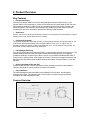
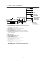
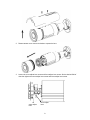
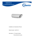
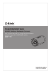
NETWORK CAMERA User’s Manual ZS10-0000002G 875 A.5 Table of Content 1. Notice of Use ............................................................................................................................... 2 2. Product Overview ........................................................................................................................ 3 2.1 Camera Parts and Definition .............................................................................................. 4 2.2 Specification ....................................................................................................................... 5 3. Camera Installation...................................................................................................................... 6 3.1 Installation .......................................................................................................................... 6 3.1.1 Drill the Mounting Location........................................................................................8 3.1.2 Positioning the Camera.............................................................................................8 3.1.3 Attaching the Camera to a Surface...........................................................................9 3.1.4 Adjusting Camera Focus...........................................................................................9 3.1.5 Using "SmartFocus" to Adjust Focus Smartly ..........................................................9 3.2 Network Camera Diagram.................................................................................................. 9 3.3 Hardware/Software Requirement..................................................................................... 10 3.4 Connecting the Camera to a Personal Computer ............................................................ 12 3.4.1Setting IP................................................................................................................. 10 3.4.2 Connect the camera to personal computer............................................................ 10 3.5 Using “IPFinder” to Search Camera’s IP Address............................................................ 14 4. Live View ................................................................................................................................... 15 4.1 Video Format.................................................................................................................... 15 4.2 Snapshot .......................................................................................................................... 15 4.3 Recording LED ................................................................................................................. 15 5. Camera Settings........................................................................................................................ 16 5.1 Image Settings ................................................................................................................. 17 5.1.1 Image ..................................................................................................................... 17 5.1.2 Image Advanced Settings ...................................................................................... 19 5.2 Network ............................................................................................................................ 20 5.2.1 Network Basic ........................................................................................................ 22 5.2.2 FTP ........................................................................................................................ 23 5.2.3 SMTP ..................................................................................................................... 22 5.2.4 NTP ........................................................................................................................ 24 5.3 System.............................................................................................................................. 23 5.3.1 DateTime................................................................................................................ 23 5.3.2 Time Stamp............................................................................................................ 24 5.3.3 User........................................................................................................................ 25 5.3.4 Audio ...................................................................................................................... 25 5.3.5 Update.................................................................................................................... 26 5.3.6 Information ............................................................................................................. 26 5.4 Application ........................................................................................................................ 27 5.4.1 Setting .................................................................................................................... 30 5.4.1.1 Video File ............................................................................................................ 28 5.4.1.2 FTP ..................................................................................................................... 29 5.4.1.3 SMTP .................................................................................................................. 31 5.4.2 Schedule ................................................................................................................ 30 5.4.2.1 Record Type........................................................................................................ 30 5.4.2.2 Period Setting...................................................................................................... 32 5.4.3 Alarm...................................................................................................................... 31 5.4.3.1 Event ................................................................................................................... 31 5.4.3.2 Action .................................................................................................................. 32 6. Reset Camera............................................................................................................................35 6.1 Software Reset................................................................................................................. 35 6.2 Hardware Reset ............................................................................................................... 35 1 1. Notice of Use This manual is designed for administrators and users of the network camera. Read it carefully before using the camera. Follow all requirements to ensure proper camera use. We are not responsible for any technical or typographical errors and reserve the right to change the product and manuals without notice. Keep this document for future reference. Please make sure the power source is 12V DC/24V AC. Only connect the camera to this required power system. The camera must be installed on a solid mounting surface. Keep the camera and accessories dry. We are not responsible for any damage caused by inappropriate use. 2 2. Product Overview Key Features Exceptional Images This camera employs a 5MP Lumii sensor that quadruples sensitivity without blurring. The camera utilizes Lumii technology to monitor the surveillance area in great detail in even the most difficult lighting conditions. It delivers crisp and detailed images that are perfect for object- and person-recognition. The camera’s high resolution also enables it to provide larger overviews, increasing the size of the surveillance area without affecting image resolution. Smartfocus A built-in nine-point focus indicator enables the camera to focus precisely and automatically on objects, relieving users of the need to adjust the focus manually. Powerful IR Illuminator The powerful IR illuminator lights objects evenly, reducing image noise and storage requirements. The IR illuminator activates automatically when the lighting dims to under 10 lux. In night mode, the illuminator enables the camera to capture images at even 0 lux. To help minimize energy usage, the camera also comes equipped with a high-power LED. ICR Day/Night Switching This camera incorporates a mechanical ICR filter to capture perfect pictures at any light level. The camera switches between its day and night modes automatically depending on the lighting conditions, enabling it to capture color video in even 0.3-lux conditions and black/white video in as little as 0 lux, ensuring crisp, clear images at all times. The camera’s megapixel resolution and mechanical ICR filter deliver sharp, detailed captures and images of distant objects in even total darkness. Housing Certified to IP66 and IP67 Certified to IP66 and IP67, the die-cast aluminum alloy housing protects the camera against extremely bad weather, making it perfect for outdoor surveillance. Easy Installation The cable-management bracket enables easy installation in any location, including walls, surfaces, and ceilings. The camera’s built-in user-friendly I/O connectors also help reduce installation time and maintenance costs. Camera Overview 3 2.1 Camera Parts and Definition 4. Power In (Red+/Black-) 5. RJ-45 Ethernet Connector 6. BNC 7. Audio Out (Green) 8. Audio In (Red) 1. sunshield 2. pipe segment3. mounting bracket 9. Alarm Out (Orange) RS485+ (Green) RS485- (Yellow) 10. GND (Gray) Alarm In (Red) Alarm Reset(Brown) 1. Rain guard/extendable sunshield: minimize the effects of rain and sunlight on image quality. 2. Pipe Segment: easy to mount at different angles. 3. Mounting Bracket: attach to a surface 4. Power In (Red+/Black-): power connector, DC12V/AC24V. 5. RJ-45 Ethernet Connector: network connection. Support PoE (Power over Ethernet). 6. BNC: video output 7. Audio Out (Green): audio output 8. Audio In (Red): audio input 9. Alarm Out (Orange): alarm signal output port. RS485+(Green): function reserved RS485- (Yellow): function reserved 10. GND: ground (electricity) in electrical circuits. Alarm In (Red): alarm signal input port. Alarm Reset (Brown): for resetting an external alarm device. 4 2.2 Specification Image System Image sensor 1/2.5" 5 MP Lumii image sensor optimized for low-light performance Effective pixels Image Compression Method Resolution/ Frame rate 2592 (H) X 1944 (V) Triple Streaming : MPEG4 x2/ Motion JPEG x1 MPEG4: HD 720P 1280 X 720 @30fps, 640 X480@30fps, 352 X192@30fps MJPEG: 640 X 480@30fps, 640 X 352@30fps Electric Sync system Built-in lens Shutter time Audio Alarm Motion detection Internal f=3.3 ~ 12 mm, F1.6, Varifocal Megapixel lens IR-corrected, Angle of view: 22∘~ 76∘(Horizontal) AES 1/10000 to 1/3.75 sec Two-way Mono Audio, Full-duplex, G.711 PCM 8kHz 64kbit/s Yes; 1x Alarm-in, 1x Alarm-out Yes; 4 x 3 MD window & 5 level sensitivity Day & Night Mode Minimum illumination Mechanical ICR Filter IR LED OFF: 0.3lux (F1.2, 50 IRE) IR LED ON: 0lux IR LED IR LED 24pcs(850nm) IR distance IR turn on status LED life TV output 25 meters (82 ft.) Under 10 lux by auto control More than 10,000 hours (50ºC) NTSC, 720 X 480 @30fps PAL, 720 X 576 @25fps Feature BLC White Balance Sharpness Saturation Brightness Contrast Other ON/Off Auto/Daylight/Fluorescent/Incandescent Low/ Middle/High Low/ Middle/High Low/ Middle/High Low/ Middle/High Mirror, Flip, system log, snapshot Power supply Power requirement DC12V/ AC24V/ PoE(IEEE 802.3af) Power consumption < 8W Power connector Screwless Terminal block Environment Operating temperature -10ºC ~ 50ºC (14ºF ~ 122 ºF) Operating humidity Storage temperature 10~ 90% RH -20ºC ~ 60ºC (-4ºF ~ 140 ºF) Network Ethernet Internet protocol Connectors 10Base-T/100Base-TX TCP/IP, UDP, HTTP, SMTP, DNS, DHCP, NTP, FTP, RTP,RTSP, ICMP, uPNP RJ-45 Ethernet 10Base-T/100Base-TX Browser IE browser 6.0 or above I/O connector Video port BNC X1, 1.0Vp-p, 75Ω Alarm port Terminal block Audio port 3.5mm Phone Jack Mechanism Dimensions(LxWxH) 300 x 88 x 86 mm (11.79" x 3.47" x 3.39") Weight 0.995 kg (2.2 lb.) Protection Class IP66 and IP67 5 3. Camera Installation Use the appropriate brackets and equipment to mount this camera. After installing the camera, your network camera should be accessed from your local network. Configure network routers first. Package Contents: Camera *1 Rubber Pad *1 Insulation caps *3 Guide Pattern Sticker *1 Self-tapping screws *3 Plastic anchor *3 Cable adaptor * 1 Power connector * 1 Printed Quick Start Guide *1 Document CD *1 3.1 Installation This section details how to set up the camera. 3.1.1 Drill the Mounting Location 1. Place the “guide pattern sticker” on the desired mounting location. 2. Drill the marked holes 3.1.2 Positioning the Camera Listed below are different ways to adjust the camera position to capture the desired field of vision. 1. Loosen the screw (a.) to rotate either the camera or “pipe segment”. Select the desired position then tighten the screw to set the position. 2. Loosen the screws on both sides (b.) to change the mounting bracket angle. Move the camera into the desired position. Tighten the screws to set the position. pipe segment screw (a.) mounting bracket screws (b.) 6 3.1.3 Attaching the Camera to a Surface 1. 2. 3. 4. Place the “rubber pad” inside the mounting bracket. Place the 3 “insulation caps” onto the “self tapping screws”. Position the mounting bracket to the desired mounting location. Screw the camera into the holes. - For cement surfaces, insert the “plastic anchors” into the holes. Align the holes in the mounting bracket. Then use the “self tapping screws” to screw the camera into the holes. - For any other surfaces, align the holes in the mounting bracket. Then use the “self tapping screws” to screw the camera into the holes. The mounting bracket can be loosened for easier cable installation. Loosen the screw (c.) on both sides to rotate the mounting bracket and adjust the cable. rubber pad insulation cap screw (c.) 3.1.4 Adjusting Camera Focus Note: This camera can be focused using a service monitor. Attach the service monitor to the BNC Cable. If no monitor is available then focus must be performed by using an internet browser to view the camera images. 1. Loosen the two screws on top of the sunshield and remove the sunshield. 7 2. Rotate camera cover counter clockwise to expose the lens. 3. Loosen the zoom adjust lever screw and focus adjust lever screw. Set the desired field of view then tighten the zoom adjust lever screw and focus adjust lever screw. zoom adjust lever focus adjust lever 8 Note: Two desiccant packs are already placed near the lens. The desiccant pack prevents fogging on the inside of the lens due to any moisture. Make adjustments within 30 minutes or the desiccant pack may absorb too much moisture and become ineffective. Desiccant packs that have absorbed too much moisture need to be replaced or reactivated. When lens adjustments are complete, reattach the camera cover and sunshield. 3.1.5 Using “SmartFocus” to Adjust Focus Smartly This network box camera provides “SmartFocus” to obtain correct focus on a subject, instead of requiring users to adjust focus manually. 9 view zones are provided. When you obtain correct focus on each view zone, the green light will be turned on. 1. Directly connect the video output cable to your monitor. 2. Press the reset button until the power is on. 3. The nine zones will appear in your monitor. Adjust the lens focus and symbols will be displayed on the top left corner of each zone. The green light: it means each view zone’s best focus position. The red arrow: it means it is near the best focus position. You just need to fine-tune it. 3.2 Network Camera Diagram Connection type:1 Connection type 2: 9 3.3 Hardware/Software Requirement Computer -Windows Vista or XP as OS -Internet Explorer Version 6.0 or later -CPU: Intel Pentium 4.2 GHz or higher -Memory: 512 MB or more -VGA card--support Direct X 9.0 or above Power Supply The camera requires a DC12V/AC24V/PoE power supply. Make sure you use the correct power supply before connecting to this network camera. Use a RJ45 network connector to connect the camera to your computer or hub switch. Hub Switch A Hub Switch is required to monitor two or more cameras from the same computer. 3.4 Connecting the Camera to a Personal Computer This section details how to access the camera from a computer. 3.4.1 Setting IP This is a network-based camera and must be assigned an IP address first. Enter a default IP address manually. The camera’s default IP address is 192.168.1.30 and submask address is 255.255.255.0. Obtain an IP address automatically from the DHCP server. You don’t need to change the camera’s IP address if your network uses a DHCP server. 3.4.2 Connect the Camera to a Personal Computer 1. Connect the network cable to the camera and then turn on the camera’s power. 2. Set the personal computer’s IP address. The camera’s default IP address: 192.168.1.30 and submask is 255.255.255.0. 3. Check that the camera and computer are connected by pinging the IP address you have set. To do this, start a command prompt and type the IP address you set. If the message “Reply from…” appears, it means the connection is done. 4. Start Internet Explorer and enter the set IP address (default is http://192.168.1.30). A login window will appear. Enter the default user name: admin and password: 1234 to login . 5. Install ActiveX viewer. It is required to monitor both MPEG4 and Motion-JPEG video modes. 10 6. Images of the camera can be viewed through Internet Explorer. Before viewing, follow these steps to enable the display. a. Enable Cookies as shown below: - In Internet Explorer, click Internet Options on the Tools menu. - On the Privacy tab, move the settings slider to Low or Accept All Cookies. - Click OK. b. Set “Browser setting when proxy sever is used” when a proxy server is used. c. Change “security” in Internet options as shown below: - On tool menu, click “Internet Option”. - Press the Security tab. - If the camera operates inside the intranet, click the “Intranet” icon. If the camera operates on the Internet, click the “Internet” icon. - Click “Custom level”. This will open the “Security Settings – Internet Zone” screen. - Scroll down to the “ActiveX controls and plug-ins” radio buttons and enable all of them as shown in the illustrations: - Press OK to save the settings. Close all Internet Explorer Windows and start a new window. This will allow the new settings to take effect. 7. Type your set IP address into the browser. 8. Then you should be able to see the camera image screen as follows: 11 3.5 Using “IPFinder” to Search Camera’s IP Address “IPFinder” is a program which helps users find network cameras Please note that “IPFinder” is only compatible with Windows Vista and Windows XP. 1. Insert the CD in the CD-ROM drive. 2. Double click “IPFinder.msi” to run the program. Follow the instructions to install,. 3. After successfully installing “IPFinder”, double click the “IPFinder” icon which is displayed in your desktop. A “IPFinder” window will pop out. The window will display a list of net cameras which you are using currently. 12 4. Click “Tool” on the tool bar to set related functions. Press “Search Network” to search cameras. Press “Set Master ID and Password” to set a master ID and password for all cameras. Or click “Management Tool” to either restart the camera, update firmware, reset all of the camera settings to default (except network settings) or reset all of the camera parameters to default. 5. After searching cameras, choose one to view detailed information. The top right frame of the “IPFinder” window will display the camera’s monitor section and the bottom right frame of “IPFinder” will display the camera’s IP address and related information. 13 6. Right click a camera to set it’s related functions. Press “Go to Presentation URL” to access the camera which you want to login. Press “Set Device ID and Password” to set the camera’s login ID and password. Click “Network Information” to configure the camera’s network settings. Or Press “Management Tool” to either restart the camera, update firmware, reset all of the camera settings to default (except network settings) or reset all of the camera parameter to default. 14 4. Live View Live view is designed for general users to control the camera. " Video Format", “Snapshot”, “Recording LED”, “Live” and “Setup” functions are listed on the live view. Please note, only administrators can access “Setup” to configure camera settings. 4.1 Video Format Select a resolution type for live view. . 4.2 Snapshot The “Snapshot” function is for snapshot capture. Press the “Snapshot” button to take a picture which will be automatically saved into an automatically created IPCAM folder on your computer. 4.3 Recording LED The recording LED becomes red when the alarm/event function is triggered. 15 5. Camera settings Click on “Setup” to configure camera settings. On the left is a navigation bar with 5 setting categories. "Image Settings", "Network Settings", "System Settings", and "Application Settings" are provided for administrators to set up the camera’s functionalities. 16 5.1 Image Settings “Image” is used to change any picture setting on the camera. Remember to click “Save” to keep your settings. 5.1.1 Image -Basic Setting Every parameter of “Basic Setting” affects the displayed image. Specify appropriate parameters in the following section. Camera Name: enter a desired network camera name. The name will be displayed at the top of the Live page. Video Codec: Choose a compression mode to be displayed in “Live View”. Compression choices include "MPEG4_1+MPEG4_2+MJPEG", "MPEG4_1+MJPEG", "MPEG4_1+MPEG4_2", and "Single MPEG4_1". - MPEG4_1 is for high-resolution live view/compression mode. 17 - MPEG4_2 is for low-resolution live view/compression mode. - MJPEG is for middle-resolution live view/compression mode. Resolution: “Resolution” and “Video Codec” are dependent fields. - If "MPEG4_1+MPEG4_2+MJPEG" is selected, "1280x720, 352x192, 640x352" can be set. - If "MPEG4_1+MJPEG" is selected, "640x480, 640x480" or "1280x720, 640x352" can be set. - If "MPEG4_1+MJPEG_2" is selected, "1280x720, 352x192" can be set. - If "Single MPEG4_1" is selected, “1280x720” can be set. *Note: the corresponding fields are listed below. Video Codec Field Resolution MPEG4_1+MPEG4_2+MJPEG 1280x720, 352x192, 640x352 MPEG4_1+MJPEG 640x480, 640x480 1280x720, 640x352 MPEG4_1+MJPEG_2 1280x720, 352x192 Single MPEG4_1 1280x720 Live View/Compression Selections MJPEG (640x352) MPEG4_1 (1280x720) MPEG4_2 (352x192) MJPEG (640x480) MPEG4_1 (640x480) MJPEG (640x352) MPEG4_1 (1280x720) MPEG4_1 (1280x720) MPEG4_2 (352x192) MPEG4_1 (1280x720) TV System: "NTSC" and "PAL" are provided for different TV system settings. Mirror: set images as left or right. Select ON or OFF to enable or disable this function. Flip: set images upside down. Select ON or OFF to enable or disable this function. -MJPEG Setting Quality: set the image’s quality as “Basic”, “Normal” or “Best”. -MPEG-4_1 Setting Bit Rate: according to your bandwidth, specify a value for data transmission rate (kbit/s). Frame Rate: frame rate is the image transfer speed. 5 is 5 images transmission per second, 10 is 10 images transmission per second, etc. If “Auto” is selected, the camera will decide the image transfer speed automatically. -MPEG-4_2 Setting The values contained in the frame rate field are displayed depending on the value you set in the video code field (please note that you have to press the save button to save the value you select 18 in the video code field first and then the corresponding values contained in the frame rate filed will be displayed for selection.) Here lists the corresponding values. Video Codec Field MPEG4_1 + MPEG4_2+MJPEG MPEG4_1+MJPEG MPEG4_1+MPEG4_2 Single MPEG4_1 Frame Rate Field 15, 7.5, 2.5 N/A 30, 15, 5 N/A Bit Rate: according to your bandwidth, specify a value for data transmission rate (kbit/s). Frame Rate: the frame rate is the image transfer speed. 15 is 15 images transmission per second, 7.5 is 7.5 images transmission per second…etc. 5.1.2 Image Advanced Settings “White Balance”, “Day and Night”, “AES”, “Lumii”, “Working Environment”, “Lens Format”, “BLC”, “Brightness”, “Contrast”, “Saturation” and “Sharpness” are provided for you to set the quality of images. Please click the “Save” button to save your image settings. -Advanced settings White Balance: select a white balance mode according to external lighting condition for the best color temperature. - Auto: adjust the white balance automatically according to the environment conditions. 19 - Daylight: adjust the white balance if the external light source is daylight. - Fluorescent: adjust the white balance if the external light source is fluorescent. - Incandescent: adjust the white balance if the external light source is incandescent. Day and Night: This function detects changes in the level of light at any time of day, and then switches to the optimum surveillance mode according to the light level. - Auto:This mode is always on. The camera will change either to Color Mode or Black and White Mode depending on the light level. AES: automatic exposure values which determine how much light passes through the camera aperture to the focus. The higher the value, the brighter the images. Lumii: Lumii function increases the sensitivity, reduces video noise in low light conditions, as well as makes night images bright and clear. This function is always active. - ON: the Lumii function is always enabled. Working Environment: - Normal: the camera’s color is automatically adjusted for outdoor environment. - Anti-Flicker: reduce color rolling for indoor environment. Lens Format: choose an appropriate lens matching with the lens size which you have installed. BLC (Backlight Compensation): this function adjusts the image to compensate for areas that are too dark due to insufficient light. - ON: enable the BLC function. - OFF: disable the BLC function. Brightness: adjust the image brightness level, to “Low”, “Middle” or “High”. The default is “Middle”. Contrast: adjust the image contrast level, to “Low”, “Middle” or “High”. The default is “Middle”. Saturation: adjust the image saturation level, to “Low”, “Middle” or “High”. The default is “Middle”. Sharpness: adjust the image sharpness level, to “Low”, “Middle” or “High”. The default is “Middle”. Default All Image parameters: All image parameters will be set back to default. 5.2 Network Click “Network” to view the current network settings, including “Network”, “FTP”, “SMTP” and “NTP”. Configure all Network, FTP, SMTP and NTP settings in the Network section. 20 5.2.1 Network Basic -Basic Setting DHCP: the IP address is automatically obtained when this is checked; otherwise, uncheck it to set up the network settings manually. If you enable the DHCP function, just specify DNS and HTTP Ports in the below fields. IP Address: specify your IP address here if you don’t select DHCP. Subnet Mask: use default number: 255.255.255.0. Default Gateway: leave blank as default setting. It is not required if it is not used. Please contact your Network Administrator for Default Gateway information. DNS: leave blank as default setting. It is not required if it is not used. Please contact your Network Administrator for DNS information. HTTP Port: We recommend using the default path. Contact your Network Administrator if it needs to be changed. Press “Save” to save your settings. Network Error Entering the wrong values can result in a network error. 21 5.2.2 FTP -FTP Server Setting Enable the FTP function and configure FTP settings here. FTP Server/ Port: enter your FTP server address. The port default value is 21. User Name: input a user login name. Password: enter a user password. File Upload Path: enter a folder path where you’d like to upload files to. 5.2.3 SMTP -SMTP Server Setting My Server Requires authorization: Check it to enable the server authorization requirement setting. SMTP Server: enter the SMTP server address. User Name: enter a user name. Password: enter a user password. Sender: enter an outgoing mail server in the “E-mail Server (SMTP)” field. 22 Receiver: enter an incoming mail server in the “E-mail Server (POP)” field. 5.2.4 NTP -NTP Server Setting NTP Server: assign an IP address or domain name for a time server. Time Zone: select a correct time zone. 5.3 System In this section, you can configure the system settings, including “Date Time”, “Time Stamp”, “Users”, “Audio”, “Update” and “Information”. Please click the “Save” button to save your settings. 5.3.1 DateTime -Current Time 23 Display the current time on the camera. Date and time will be changed after you configure it in the “New Time” section. -New Time You can set the camera time by “Set Manually”, “Synchronize with Computer Timer” and “Synchronize with NTP Server”. Then, select a date format type. “YYYY/MM/DD’, “MM/DD/YYYY” and “DD/MM/YYYY” are choices provided. Set Manually: set date and time manually. Synchronize with Computer Timer: synchronize your camera’s date and time with the computer’s timer. Synchronize with NTP Server: synchronize your camera’s date and time with the NTP server’s timer. 5.3.2 Time Stamp - Time Stamp Enable the “Enable Date and Time Stamp” function to display the current time on the “Live” page. Enable Date and Time Stamp: check “Enable Date and Time Stamp” to activate this function. Date Format: select a date format. “YYYY/MM/DD”, “MM/DD/YYYY” and “DD/MM/YYYY” are choices provided. 24 5.3.3 User - User List Displays the list of users. Only two roles can be specified, administrator (admin) and guest (viewer). If you want to delete a user, select a user and then press the “Delete User” button. - Add/Modify User You can add a new user or modify a user’s information or authority. To add/modify a new user, enter a user name and password. Then, specify his/her role as Admin or Viewer. Press “Add” to add a user or to modify a user’s password or authority 5.3.4 Audio Audio Recording: if the camera is connected to an external microphone, select “ON” to record the external voice or “OFF” to disable the audio recording function. Audio Playing: if the camera is connected to an external speaker, select “ON” to output audio signals from the computer to outside. Alarm level: specify a value for voice volume in the “Alarm Level” field. The volume increase in the order of “1”, “2”, “3” and “4”. This function only works when the Audio Playing function is enabled. 25 5.3.5 Update This function is designed to update firmware. Stop all camera operations when you update firmware. Do not turn off power or disconnect the internet connection during the firmware update process. Click “Restart Camera” after you have updated firmware successfully. 5.3.6 Information It displays all login and alarm records. 26 5.4 Application In this section, you can configure system settings, including “Setting” (Video File, FTP, and SMTP), “Schedule” (Record Type and Period Setting) and “Alarm” (Event and Action). 27 5.4.1 Setting Set video record time by selecting a value in the “AVI duration” field and a video record format when the alarm is triggered. Press the “Save” button to save your settings. 5.4.1.1 Video File 28 Set video record time by selecting a value in the “AVI duration” field and set a video format when the alarm is triggered. The values contained in the AVI format fields are displayed depending on the values you set in the video code and resolution fields in the image setting page. The corresponding values are listed below. Video Codec Field MPEG4_1 + MPEG4_2+MJPEG MPEG4_1 + MJPEG MPEG4_1+MPEG4_2 Single MPEG4_1 Resolution Field 1280x720,352x192, 640x352 640x480,640x480 1280x720,640x352 1280x720,352x192 1280x720 AVI Format Field MPEG4(720) MPEG4(CIF) MPEG4(VGA) MPEG4(720) MPEG4(720)/ MPEG4(CIF) MPEG4(720) AVI duration: select video record time by selecting a value in the “AVI duration” field once the alarm is triggered. AVI Format: select a video record format. 5.4.1.2 FTP Set a format of video which is set to be saved to FTP. The values contained in the file format field are displayed depending on the values you set in the video code field of the image setting section. The corresponding values are listed below. Video Codec Field MPEG4_1 + MPEG4_2+MJPEG MPEG4_1+MJPEG MPEG4_1+MPEG4_2 Single MPEG4_1 File Format MPEG4 JPEG MPEG4 FTP Networking section: it displays FTP information. File Format: select a format of file which set to be saved to FTP. Click “Save” to save your settings. 29 5.4.1.3 SMTP You can set the number and type of images which you want to receive via e-mail. The values contained in the “Attach File Format” field are displayed depending on the values you set in the video code field in the image setting page. The corresponding values are listed below. SMTP Server: it displays the SMTP address which can be set in Network>SMTP. Email Address: the receiver’s mail address which can be set in Network>SMTP. Attach File Number: specify the number of files which can be attached to a mail. Attach File Format: select a format of files which can be attached to a mail. 5.4.2 Schedule This function can be activated at preset times, in a repeating pattern on selected weekdays.. 5.4.2.1 Record Type Two recording types can be set at the same time, which is FTP recording . Enable Record-Upload Via FTP: save files on the FTP server. Press “Save” to save your settings. 30 5.4.2.2 Period Setting Store image files based on the schedule you set. Configure settings and then press “Save” to save settings. Note: if you set up recording schedules, the “AVI duration” function (refer to 5.4.1.1 for related settings) or the “alarm duration” function (refer to 5.4.3 for related settings) can not work. 5.4.3 Alarm You can set to trigger alarms on the conditions that an event or action signal has been sent to the camera. 5.4.3.1 Event 31 Trigger an Alarm When Ethernet is Lost: set an alarm condition when Ethernet disconnected. Digital Input: send a signal to the camera to trigger an alarm. Check it to enable this function. Then, set digital input as “High” or “Low” Motion Detection: this function is designed to record video once the camera detects a motion condition. Select “Disable” to disable this function or “Enable” to enable this function. Sensibility: set sensibility level as “Lowest”, “Low”, “Medium”, “High” or “Highest”. Or input a value from 0 to 99 in the customized threshold field. Higher number gets higher sensitivity. Press “Save” to save your settings. Select a motion detection area by clicking squares displayed on the screen to disable a detection area. 12 motion detection areas are choices provided. Then press “Save Motion Window” to save your motion detection area setting. 5.4.3.2 Action Configure image transfer settings after triggering an alarm. Select an image transfer method. You could upload the file via FTP server or send via SMTP. Note that you can only choose one transfer method. Digital Output: select “OFF” to disable this function or “ON” to enable this function. If select “ON”, choose an output file’s resolution as “Low” or “High”. Digital Output - If you want to set digital output function start, you need to set ON. After that, you need to set “Active Type” (Low or High) about digital output by the hardware. Alarm duration - The alarm time period of digital output. 32 6. Reset Camera There are two ways to reinstate the Factory Default settings for the camera. 6.1 Software Reset Login as the administrator to “Live View”. Go into Setup. Then click System Update. Choose the desired option: Restart Camera – The camera is restarted without changing any settings. Typically used after updating firmware. After clicking, a pop up will appear asking you to confirm. Click Yes. Factory Default – Resets the camera to factory settings but keeps the Network settings. After clicking, a pop up will appear asking you to confirm. Click Yes. Hard factory default – Resets the camera to factory settings and will cause all parameters (including the IP address) to be reset. After clicking, a pop up will appear asking you to confirm. Click Yes. 6.2 Hardware Reset If the Internet Explorer browser cannot be access for whatever reason or Software Reset does not work then use Hardware Reset. 1. Loosen the two screws on top of the sunshield and remove the sunshield. 33 2. Rotate camera cover counter clockwise to expose the lens. 3. User a screwdriver to press the hardware reset button. Then assemble the front cap & the sun shield back Reset Button 34 35