1
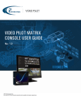
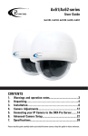
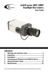
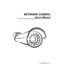
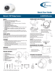
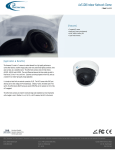
Ax41C1M MP NETWORK Camera
Instruction Manual
CONTENTS
SAFETY INFORMATION..................................................... 2
Product Overview ............................................................. 4
SPECIFICATION..................................................................7
INSTALLATION................................................................ 9
Before attempting to connect or operate this product, please read these
instructions carefully and save this manual for future use.
SAFETY INFORMATION
When installing your Annexxus system, be sure to avoid:
• excessive heat, such as direct sunlight or heating appliances
• moisture, dust, and smoke
• strong magnetic fields
• close to sources of powerful electromagnetic radiation, such as radios or TV transmitters
• close to humid or excessively dusty places
• where exposed to mechanical vibrations
• close to fluorescent lamps or objects reflecting light
• under unstable light sources (may cause flickering)
• temperatures below 10° Celsius or 14° Fahrenheit and above 50° Celsius or 122° Fahrenheit for AX41C1M
Power Supply
• Ensure the supplied voltage meets the power consumption
requirements of this camera before powering the camera on.
Incorrect voltage may cause irreparable damage to the video
camera and will effectively void the camera warranty
Cleaning
• For maximum optical clarity, the camera dome or lens must remain clean. Use a soft, dry cloth to remove finger prints or dust
from the dome cover.
• Use a blower to remove dust from the lens.
• Clean the body with a soft, dry cloth. If it is very dirty, use a cloth dampened with a small quantity of neutral detergent, then
wipe dry.
• Do not use volatile solvents such as alcohol, benzene, or thinners, as they may damage the surface finishes.
Servicing
• To avoid electrical shock and to preserve the product warranty,
DO NOT disassembles the camera. Refer servicing to qualified
personnel only.
2
SAFETY INFORMATION
The triangle symbol with lightning arrow indicates
that ungrounded “Hazardous Voltage” exists within
the unit. The voltage level may cause personal
electric shock hazards.
The triangle symbol with exclamation mark
indicates that there are important operation and
maintenance instructions in the Instruction Manual.
3
PRODUCT OVERVIEW
1. Key Features
Exceptional Images
This camera employs a 5MP CMOS sensor that quadruples sensitivity
without blurring. The camera’s technology provides picture with greater
detail in even the most difficult lighting conditions. It delivers crisp
images that are perfect for object- and person-recognition.
Smart focus
A built-in nine-point focus indicator enables the camera to focus
precisely and automatically on objects, relieving users of the need to
adjust the focus manually.
Easy Installation
The cable-management bracket enables easy installation in any
location, including walls, surfaces, and ceilings. The camera’s built-in
user-friendly I/O connectors also help reduce installation time and
maintenance costs.
SD Memory Card Storage
The camera is equipped with an SD card that enables round-the-clock
monitoring, ensuring that the camera can store captured images
even in the event that its network connection goes down. The
camera delivers all-day surveillance and round-the-clock security.
4
PRODUCT OVERVIEW
2. Camera Overview
5
PRODUCT OVERVIEW
2.0 Camera Parts and Definition
• SD card slot: insert a SD card into this slot for recording and storage
• Reset button: restart the system. Hold down the reset button for about 5 seconds to restart the camera. Or hold down the reset button for longer than 5 seconds to reset
all of the camera parameters to factory default.
• Level: for future use
• RJ45 Ethernet connector/PoE: insert the RJ45 cable for network connection. It also
supports
• PoE (Power over Ethernet)
• Power Indicator: power indicator. Red light indicates power connection
• Power terminal: DC12V/AC24V, red port: power +/white port: power –. Make sure
to connect the power connector to correct ports (+ and –) when the power supply is
DC12V
• RS485+: function reserved
• RS485-: function reserved
• GND: ground
• AUDIO-IN: audio input port
• AUDIO-OUT: audio output port
• ALM-OUT: alarm output port. Connect to external devices, such as relays or LEDs
• ALM-IN: alarm input port
• ALM-RST: alarm reset
• VIDEO: video output port
LED indicators
LED
Color
Indication
Ethernet/PoE Green
Network connection.
Orange
Power over Ethernet
Unlit
No network connection
6
SPECIFICATION
Image system
Image sensor
Effective pixels
Image Compression Method
Resolution
Service Monitor output
(for installation)
Electric
Sync system
Lens Mount
Gamma correction
Minimum illumination
White balance
BLC
Audio
Alarm
SD card slot
Intelligent video
Power requirement
Power requirement
Power consumption
Power connector
Environment
Operating temperature
Operating humidity
Storage temperature
Network
Ethernet
Internet protocol
Control interface
1/2.5" 5 MP CMOS sensor image optimized for low light performance
Full scanning mode:2592 (H) X 1944 (V)
MPEG-4 x 2/Motion JPEG
HD 720P (1280 X 720)
VGA (640 X 480), 352 (640 X 352),192 (352 X 192)
One Jack for composite video (Support PAL/ NTSC TV mode only)
HD 720P 1280 X 720 @25 fps for PAL; @30 fps for NTSC
VGA (640 X 480), 352 (642 X 352), 192 (352 X 192) @25 fps for PAL;
@30 fps for NTSC
Internal
CS mount
0.45
0.3 lux. @ TV-Out (F1.2) 10 IRE
2500ºK~9600ºK
On and OFF
Two-way Mono Audio; Full-duplex
Yes; 1x DI & 1x DO
Support micro SDHC card (up to 32 Gb)
Video motion detection
DC12V/AC24V/ PoE
5W Max
Screwless Terminal Block
-10ºC ~ 50ºC (14ºF ~ 122ºF)
80% RH or less
-20ºC ~ 60ºC (-4ºF ~ 140ºF)
10/100 base-T Ethernet connection for LAN/WAN
TCP/IP, UDP, HTTP, SMTP, DNS, DHCP, NTP, DDNS, FTP, RTP,RTSP
over TCP or UDP, ICMP, IGMP, uPNP
IE browser 6.0 or above
7
SPECIFICATION
I/O connector
Network port
Video port
Audio in & out port
Mechanism
Dimensions((LxWxH)
Weight (Camera Only)
Warranty
RJ45 with LEDs
YES
YES
114 x 66 x 65 mm (4.5" x 2.6" x 2.6")
320g (0.70 lb)
3 year labour and part
NOTE:The specification is subject to change without notice.
8
INSTALLATION
3. Camera Installation
Use the appropriate brackets and equipment to mount this camera.
After installing the camera, your network camera should be accessed
from your local network. Configure network routers first.
Package Contents:
• Network Box Camera
• CD containing user manual and IPFinder software
• 2 pin screw terminal block (x 1)
• 12 pin screw terminal block (x 1)
• CS Ring (x 1 )
• BNC Connector (x1)
3.1.5 Using “Smart Focus” to Adjust Focus Smartly
This network box camera provides “Smart Focus” to obtain correct
focus on a subject, instead of requiring users to adjust focus
manually. 9 view zones are provided. When you obtain correct focus
on each view zone, the green light will be turned on.
1. Directly connect the video output cable to your monitor.
2. Press the reset button until the power is on.
3. The nine zones will appear in your monitor. Adjust the lens focus and symbols will be displayed on the top left corner of each
zone.
• The green light: it means each view zone’s best focus position.
• The red arrow: it means it is near the best focus position. You just
need to fine-tune it.
9
INSTALLATION
3.2 Network Camera Diagram
Connection type: 1
Crossover direct connection
i³ iP-Pro Server
Connection type: 2
LAN
VIA a Gigabit Switch
i³ iP-Pro Server
3.3 Hardware/Software Requirement
• Computer
• i³ SRX-Pro/iP-Pro Version 1.610 or higher
• Windows Vista or XP as OS
• Internet Explorer Version 6.0 or later
• CPU: Intel Pentium 4.2 GHz or higher
• Memory: 512 MB or more
• VGA card--support Direct X 9.0 or above
• Power Supply
The camera requires a DC12V/AC24V/PoE power supply. Make
sure you use the correct power supply before connecting to this
network camera. Use a RJ45 network connector to connect the
camera to your computer or hub switch.
• Switch
A one Gigabit Switch is required to monitor two or more cameras
from the same computer.
10
INSTALLATION
• SD card
The camera supports Micro SDHC memory cards up to 32GB.
Images can be recorded when the SD card is being inserted into
the camera. Insert a SD card before switching on the camera. The
SD card may not be detected if it is inserted while the camera is on.
3.4 Connecting the Camera to a Personal Computer
This section details how to access the camera from a computer.
3.4.1 Setting IP
This is a network-based camera and must be assigned an IP
address first.
• Enter a default IP address manually. The camera’s default IP
address is 192.0.0.16 and submask address is 255.255.255.0.
• Obtain an IP address automatically from the DHCP server. You
don’t need to change the camera’s IP address if your network uses
a DHCP server.
3.4.2 Connect the Camera to a Personal Computer
1. Connect the network cable to the camera and then turn on the camera’s power.
2. Set the personal computer’s IP address. The camera’s default IP address: 192.0.6.16 and submask is 255.255.255.0.
11
INSTALLATION
3.Check that the camera and computer are connected by pinging
the IP address you have set. To do this, start a command prompt
and type the IP address you set. If the message “Reply from…”
appears, it means the connection is done.
4.Start Internet Explorer and enter the set IP address (default is
http://192.0.0.16). A login window will appear. Enter the default
user name: admin and password: 1234 to login.
5.Install ActiveX viewer. It is required to monitor both MPEG4 and
Motion-JPEG video modes.
6.Images of the camera can be viewed through Internet Explorer.
Before viewing, follow these steps to enable the display.
a.Enable Cookies as shown below:
- In Internet Explorer, click Internet Options on the Tools menu.
- On the Privacy tab, move the settings slider to Low or Accept
All Cookies.
- Click OK.
b.Set “Browser setting when proxy sever is used” when a proxy
server is used.
c.Change “security” in Internet options as shown below:
- On tool menu, click “Internet Option”.
- Press the Security tab.
- If the camera operates inside the intranet, click the “Intranet”
icon. If the camera operates on the Internet, click the “Internet”
icon.
12
INSTALLATION
- Click “Custom level”. This will open the “Security Settings – Internet Zone” screen.
- Scroll down to the “ActiveX controls and plug-ins” radio buttons and enable all of them as shown in the illustrations:
- Press OK to save the settings. Close all Internet Explorer Windows and start a new window. This will allow the new settings to take effect.
7. Type your set IP address into the browser.
8. Then you should be able to see the camera image screen as
follows:
13
INSTALLATION
3.5 Using “Annexxus Finder” to Search Camera’s IP Address
“Annexxus Finder” is a program which helps users finds network
cameras. Please note: “Annexxus Finder” is only compatible with
Windows XP.
1. Insert the CD in the CD-ROM drive.
2. Double click “AnnexxusFinder.exe” to run the program. Follow the
instructions to install.
3. After successfully installing “Annexxus Finder”, double click the
“Annexxus Finder” icon which is displayed in your desktop. An
“Annexxus Finder” window will pop out. The window will display a
list of net cameras which you are using currently.
14
INSTALLATION
To edit user accounts for the selected IP camera, do the
following:
1. Select desired camera in the Annexxus Finder software by
double clicks
2. Go to the Change IP Address and enter the correct data for the
IP camera
3. There is NO need for Input Password. It is ONLY pertaining to
upgrading firmware
4. Live View
Live view is designed for general users to control the camera. “ Video
Format”, “Snapshot”, “Recording LED”, “Live” and “Setup” functions
are listed on the live view. Please note, only administrators can
access “Setup” to configure camera settings.
4.1 Video Format
Select a resolution type for live view.
15
INSTALLATION
4.2 Snapshot
The “Snapshot” function is for snapshot capture. Press the
“Snapshot” button to take a picture which will be automatically
saved into an automatically created C:\Document and Settings\
Administrator\My Documents\IPCAM folder on your computer.
5. Camera settings
Setup Button
Click on “Setup” to configure camera settings.
5.1 Image Settings
16
INSTALLATION
“Image” is used to change any picture setting on the camera.
Remember to click “Save” to keep your settings.
5.1.1 Image
Basic Setting
Every parameter of
“Basic Setting” affects the
displayed image. Specify
appropriate parameters in
the following section.
• Camera Name: enter a
desired network camera
name. The name will be
displayed at the top of the
Live page.
• Video Codec: Choose a
compression mode to be
displayed in “Live View”.
17
INSTALLATION
Advance Setting
• TV System: “NTSC” and “PAL” are provided for different TV system settings.
• Mirror: set images as left or right. Select ON or OFF to enable or
disable this function.
• Flip: set images upside down. Select ON or OFF to enable or
disable this function.
-MJPEG Setting
• Quality: set the image’s quality as “Basic”, “Normal” or “Best”.
-H.264 Setting
• Bit Rate: according to your bandwidth, specify a value for data
transmission rate (kbit/s).
• Frame Rate: frame rate is the image transfer speed. 5 is 5 images
transmission per second, 10 is 10 images transmission per
second, etc. If “Auto” is selected, the camera will decide the image
transfer speed automatically. Min=500 or max=10000
18
INSTALLATION
-MPEG4 Setting
• The values contained in the frame rate field are displayed
depending on the value you set in the video code field (please note
that you have to press the save button to save the value you select
in the video code field first and then the corresponding values
contained in the frame rate filed will be displayed for selection.)
Here lists the corresponding values. Min=500 or max=10000
Video Codec Field
H.264+MPEG4+ MPEG
H.264+MJPEG
H.264+MPEG4
H.264
Frame Rate Field
30, 15, 5, Auto
• Bit Rate: according to your bandwidth, specify a value for data
transmission rate (kbit/s).
Frame Rate: the frame rate is the image transfer speed.
5.1.2 Image Advanced Settings
19
INSTALLATION
“White Balance”, “Day and Night”, “AES”, “Lumii”, “Working
Environment”, “Lens Format”, “BLC”, “Brightness”, “Contrast”,
“Saturation” and “Sharpness” are provided for you to set the quality
of images. Please click the “Save” button to save your image
settings.
Advanced settings
• White Balance: select a white balance mode according to external
lighting condition for the best color temperature.
• Auto: adjust the white balance automatically according to the
environment conditions.
• Daylight: adjust the white balance if the external light source is
daylight.
• Fluorescent: adjust the white balance if the external light source is
fluorescent.
• Incandescent: adjust the white balance if the external light source is
incandescent.
• Day and Night: detects changes in the level of light at any time of
day, and then switches to the optimum surveillance mode according
to the light level.
• Auto: This mode is always on. The camera will change either to
Color Mode or Black/White Mode depending on the light level.
• AES: automatic exposure values which determine how much light
passes through the camera aperture to the focus. The higher the
value, the brighter the images.
• Lumii: Lumii function increases the sensitivity, reduces video noise
in low light conditions, as well as makes night images bright and
clear. This function is always active.
- ON: the Lumii function is always enabled.
• Working Environment:
- Normal: the camera’s color is automatically adjusted for outdoor environment.
- Anti-Flicker: reduce color rolling for indoor environment.
20
INSTALLATION
• ON: enable the BLC function.
• OFF: disable the BLC function.
- Brightness: adjust the image brightness level, to “Low”, “Middle” or “High”. The default is “Middle”.
- Contrast: adjust the image contrast level, to “Low”, “Middle” or “High”. The default is “Middle”.
- Saturation: adjust the image saturation level, to “Low”, “Middle” or “High”. The default is “Middle”.
- Sharpness: adjust the image sharpness level, to “Low”, “Middle” or “High”. The default is “Middle”.
Communication:
Click “Communication” to view the current network settings, including
“Network”, and “NTP”. Configure all Network, and NTP settings in the
Network section.
1. DHCP: the IP address is automatically obtained when this is
checked; otherwise, uncheck it to set up the network settings
manually. If you enable the DHCP function, just specify DNS and
HTTP Ports in the below fields.
2. IP Address: specify your IP address here if you don’t select DHCP.
3. Subnet Mask: use default number: 255.255.255.0.
4. Default Gateway: leave blank as default setting. It is not required
if it is not used. Please contact your Network Administrator for
Default Gateway information.
21
INSTALLATION
5. DNS: leave blank as default setting. It is not required if it is
not used. Please contact your Network Administrator for DNS
information.
6. HTTP Port: We recommend using the default path. Contact your
Network Administrator if it needs to be changed.
7. Press “Save” to save your settings.
NTP Server Setting
• NTP Server: assign an IP address or domain name for a time server.
• Time Zone: select a correct time zone.
5.3 System
In this section, you can configure the system settings, including
“Time Stamp”, “Current Date & Time” and “New Date & Time”.
22
INSTALLATION
Current Time
Display the current time on the camera. Date and time will be
changed after you configure it in the “New Time” section.
New Time
You can set the camera time by, “Synchronize with Computer Time”
or “Synchronize with NTP Server”. Then, select a date format type.
“YYYY/MM/DD’, “MM/DD/YYYY” and “DD/MM/YYYY” are choices
provided.
• Synchronize with Computer Time: synchronize your camera’s date and time with the computer’s time.
• Synchronize with NTP Server: synchronize your camera’s date and time with the NTP server’s time.
5.3.5 Update
23
INSTALLATION
This function is designed to update firmware. Stop all camera
operations when you update firmware. Do not turn off power or
disconnect the internet connection during the firmware update
process. Click “Restart Camera” after you have updated firmware
successfully.
• Restart Camera – The camera is restarted without changing any
settings. Typically used after updating firmware. After clicking, a
pop up will appear asking you to confirm. Click Yes.
• Factory Default – Resets the camera to factory settings but keeps
the Network settings. After clicking, a pop up will appear asking
you to confirm. Click Yes.
• Hard factory default – Resets the camera to factory settings and
will cause all parameters (including the IP address) to be reset.
After clicking, a pop up will appear asking you to confirm. Click
Yes.
5.3.3 User
User List
Displays the list of users. Only two roles can be specified, administrator
(admin) and guest (viewer). If you want to delete a user, select a user
and then press the “Delete User” button.
24
INSTALLATION
Add/Modify User
You can add a new user or modify a user’s information or authority.
• To add/modify a new user, enter a user name and password.
Then, specify his/her role as Admin or Viewer.
• Press “Add” to add a user or to modify a user’s password or authority
5.3.6 Logs
It displays all login and alarm records.
5.4.3 Alarm
You can set to trigger alarms on the conditions that an event or
action signal has been sent to the camera.
25
INSTALLATION
• Trigger an Alarm When Ethernet is Lost: set an alarm condition
when Ethernet disconnected.
• Digital Input: send a signal to the camera to trigger an alarm. Check
it to enable this function. Then, set digital input as “High” or “Low”
• Motion Detection: this function is designed to record video once the
camera detects a motion condition. Select “Disable” to disable this
function or “Enable” to enable this function. Please note this is for future use.
• Sensibility: set sensibility level as “Lowest”, “Low”, “Medium”,
“High” or “Highest”. Or input a value from 0 to 99 in the customized
threshold field. Higher number gets higher sensitivity.
• Press “Save” to save your settings.
• Action: Configure image transfer settings after triggering an alarm.
- Digital Output: select “OFF” to disable this function or “ON” to enable this function. If select “ON”, choose an output file’s
resolution as “Low” or “High”.
- Digital Output - If you want to set digital output function start, you
need to set ON. After that, you need to set “Active Type” (Low or
High) about digital output by the hardware.
• Alarm duration - The alarm time period of digital output.
26
i³ INTERNATIONAL INC.
1.866.840.0004
www.i3international.com
U.S.A. 440 Lawrence Bell Drive,
Suite 16, Williamsville
NY, 14221
Canada 780 Birchmount Road,
Unit 16, Scarborough,
ON, M1K 5H4