1
APPLICATION NOTE
M16C/Tiny Series
Operation of Serial I/O (Reception in Clock-Asynchronous Serial
I/O Mode)
1.
Abstract
In receiving data in clock-asynchronous serial I/O mode, choose functions from those listed in Table1.
Operations of the checked items are described below.
Table 1. Choosed Functions
Item
Transfer clock
Set-up
Yes
source
Internal clock (f1/f2/f8/f32)
External clock (CLKi pin)
Item
_________ _________
CTS /RTS
Set-up
Yes
_________ _________
CTS /RTS shared pin
_________ _________
separated function
CTS /RTS separated
(Note 1)
________
RTS function
Yes
________
RTS function enabled
________
RTS function disabled
Data logic select
Yes
(Note 2)
TxD, RxD I/O
polarity reverse
No reverse
Reverse
Yes
No reverse
Reverse
function (Note 2)
Note 1: UART0 only
Note 2: UART2 only.
2.
Introduction
The explanation of this issue is applied to the following condition:
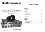
Applicable MCU: M16C/26, M16C/26A, M16C/28, M16C/29 Group
This program can also be used when operating other microcomputers within the M16C family, provided they
have the same SFR (Special Function Registers) as the M16C/26, M16C/26A, M16C/28, M16C/29
microcomputers. However, some functions may have been modified.
Refer to the User’s Manual for details. Use functions covered in this Application Note only after careful
evaluation.
REJ05B0625-0110/Rev.1.10
May 2005
Page 1 of 12
M16C/Tiny Series
Operation of Serial I/O (Reception in Clock-Asynchronous Serial I/O Mode)
3.
(1)
(2)
(3)
(4)
Operation of Serial I/O
_________
Setting the receive enable bit to “1” readies data-receivable status. At this time, output from the RTSi
pin goes to “L” level to inform the transmission side that the receivable status is ready.
_________
When the first bit (the start bit) of reception data is received from the RxDi pin, output from the RTSi
goes to “H” level. Then, data is received, bit by bit, in sequence: LSB, ····, MSB, and stop bit(s).
When the stop bit(s) is (are) received, the content of the UARTi receive register is transmitted to the
UARTi receive buffer register. At this time, the receive complete flag goes to “1” to indicate that the
reception is completed, the UARTi receive interrupt request bit goes to “1”, and output from the RTS
pin goes to “H” level.
The receive complete flag goes to “0” when the lower-order byte of the UARTi buffer register is read.
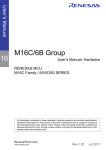
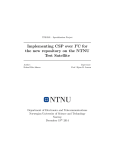
Figure 1 shows the operation timing.
REJ05B0625-0110/Rev.1.10
May 2005
Page 2 of 12
M16C/Tiny Series
Operation of Serial I/O (Reception in Clock-Asynchronous Serial I/O Mode)
Example of wiring
Microcomputer
Transmitter side IC
RxDi
RTSi
TxD
Port
Example of operation
(3)Reception is complete
(1)Reception enabled
(4)Read of reception
data
(2)Start reception
BRGi count source
“1”
Receive enable bit
(RE)
“0”
RxDi
Start bit
Sampled “L”
D0
D1
D7
Stop bit
Receive data taken in
Transfer clock
Receive complete
flag (RI)
“1”
Reception started when transfer clock is generated by
Transferred from UARTi receive register to
falling edge of start bit
UARTi receive buffer register
“0”
Read UARTi receive buffer register
“1”
RTSi
“0”
Receive interrupt
request bit (IR)
“1”
“0”
Set to “0” upon accepting an interrupt request or by writing in program.
i = 0 to 2
Shown in ( ) are bit symbols.
The above timing applies to the following settings:
• Transfer data length is 8 bits.
• Parity is disabled.
• One stop bit.
• RTS function is selected.
Figure 1. Operation Timing of Reception in Clock-Asynchronous Serial I/O Mode
REJ05B0625-0110/Rev.1.10
May 2005
Page 3 of 12
M16C/Tiny Series
Operation of Serial I/O (Reception in Clock-Asynchronous Serial I/O Mode)
3.1 Register Setting
To enable the operation defined in “Section 3. Operation of timer A”, the following register settings must be
taken place step by step. For detail configuration of each register, please refer to M16C/26 Group hardware
manual, M16C/26A Group hardware manual, M16C/28 Group hardware manual, M16C/29 Group hardware
manual.
3.1.1 UART0, 1
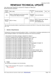
(1) Setting UARTi transmit/receive mode register (i=0, 1)
b7
b0
0 0 0 0 0 1 0 1
SMD2 to SMD0 Serial I/O Mode Select Bit
101 : UART mode transfer data 8 bits long
CKDIR
Internal/external Clock Select Bit
0: Internal clock
STPS
Stop Bit Length Select Bit
0 : One stop bit
PRY
Odd/even Parity Select Bit (Effective when PRYE = 1)
0 : Odd parity
PRYE
Parity Enable Bit
0 : Parity disabled
(b7)
Set to “0”
(2) Setting UARTi transmit/receive control register 0 (i=0,1)
b7
0 0
b0
0
1
CLK1 to CLK0 BRG Count Source Select Bit
00 : f1SIO or f2SIO is selected
01 : f8SIO is selected
10 : f32SIO is selected
11 : Do not set to this value
CRS
CTS/RTS Function Select Bit
1 : RTS function is selected
TXEPT
Transmit Register Empty Flag
0: Data present in transmit register (during transmission)
1: No data present in transmit register (transmission completed)
CRD
CTS/RTS Disable Bit
0 : CTS/RTS function enabled
NCH
Data Output Select Bit
0: TxDi pins are CMOS output
1: TxDi pins are N-channel open-drain output
CKPOL
Set to “0” in clock asynchronous serial I/O mode
UFORM
Set to “0” in clock asynchronous serial I/O mode
REJ05B0625-0110/Rev.1.10
May 2005
Page 4 of 12
M16C/Tiny Series
Operation of Serial I/O (Reception in Clock-Asynchronous Serial I/O Mode)
(3) Setting UART transmit/receive control register 2
b7
b0
0 0 0 0 0 0
U0RRM,U1RRM Set to “0” in clock asynchronous serial I/O mode
CLKMD0
Set to “0” in clock asynchronous serial I/O mode
CLKMD1
Set to “0” in clock asynchronous serial I/O mode
RCSP
Separate UART0 CTS/RTS Bit
0 : CTS/RTS shared pin
1 : CTS/RTS separated (CTS0 supplied from the P64 pin)
(b7)
Set to “0”
(4) Setting UARTi baud rate generation register (i=0,1)
b7
b0
Can be set to 0016 to FF16 (Note)
Note: Write to UARTi baud rate generation register when transmission/reception is halted.
(5) Transmission enabled (UARTi transmit/receive control register 1) (i=0,1))
b7
0 0 0
b0
1
RE
Receive Enable Bit
1 : Reception enabled
(6) Checking the status of UARTi receive buffer register (i=0,1)
b7
b0
0 0 0
RI
Receive Complete Flag
0 : No data present in UiRB register
1 : Data present in UiRB register
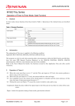
(7) Reading out reception data and checking error (Read UARTi reception buffer register (i=0,1))
(b15)
b7
(b8)
b0 b7
b0
Reception data
REJ05B0625-0110/Rev.1.10
OER
Overrun Error Flag
0 : No overrun error
1 : Overrun error found
FER
Framing Error Flag
0 : No framing error
1 : Framing error found
PER
Parity Error Flag
0 : No parity error
1 : Parity error found
SUM
Error Sum Flag
0 : No error
1 : Error found
May 2005
Page 5 of 12
M16C/Tiny Series
Operation of Serial I/O (Reception in Clock-Asynchronous Serial I/O Mode)
3.1.2 UART2
(1) Setting UART2 transmit/receive mode register
b7
b0
0 0 0 0 0 1 0 1
SMD2 to SMD0 Serial I/O Mode Select Bit
101 : UART mode transfer data 8 bits long
CKDIR
Internal/external Clock Select Bit
0: Internal clock
STPS
Stop Bit Length Select Bit
0 : One stop bit
PRY
Odd/even Parity Select Bit (Effective when PRYE = 1)
0 : Odd parity
PRYE
Parity Enable Bit
0 : Parity disabled
IOPOL
TxD, RxD I/O Polarity Reverse Bit
0 : No reverse
(2) Setting UART2 transmit/receive control register 0
b7
0 0
b0
0
1
CLK1 to CLK0 BRG Count Source Select Bit
00 : f1SIO or f2SIO is selected
01 : f8SIO is selected
10 : f32SIO is selected
11 : Do not set to this value
REJ05B0625-0110/Rev.1.10
CRS
CTS/RTS Function Select Bit
1 : RTS function is selected
TXEPT
Transmit Register Empty Flag
0: Data present in transmit register (during transmission)
1: No data present in transmit register (transmission completed)
CRD
CTS/RTS Disable Bit
0 : CTS/RTS function enabled
NCH
Data Output Select Bit
0: TxD pins are CMOS output
1: TxD pins are N-channel open-drain output
CKPOL
Set to “0” in clock asynchronous serial I/O mode
UFORM
Set to “0” in clock asynchronous serial I/O mode
May 2005
Page 6 of 12
M16C/Tiny Series
Operation of Serial I/O (Reception in Clock-Asynchronous Serial I/O Mode)
(3) Setting UART2 transmit/receive control register 1
b7
b0
0 0 0
U2RRM
Set to “0” in clock asynchronous serial I/O mode
U2LCH
Data Logic Select Bit
0 : No reverse
U2ERE
Error Signal Output Enable Bit
Set to “0” in clock asynchronous serial I/O mode
(4) Setting UART2 baud rate generation register
b7
b0
Can be set to 0016 to FF16 (Note)
Note: Write to UART2 baud rate generation register when transmission/reception is halted.
(5) Transmission enabled (UART2 transmit/receive control register 1)
b7
0 0 0
b0
1
RE
Receive Enable Bit
1 : Reception enabled
(6) Checking the status of UARTi receive buffer register (i=0,1)
b7
b0
0 0 0
RI
Receive Complete Flag
0 : No data present in U2RB register
1 : Data present in U2RB register
(7) Reading out reception data and checking error (Read UART2 reception buffer register)
(b15)
b7
(b8)
b0 b7
b0
Reception data
REJ05B0625-0110/Rev.1.10
OER
Overrun Error Flag
0 : No overrun error
1 : Overrun error found
FER
Framing Error Flag
0 : No framing error
1 : Framing error found
PER
Parity Error Flag
0 : No parity error
1 : Parity error found
SUM
Error Sum Flag
0 : No error
1 : Error found
May 2005
Page 7 of 12
M16C/Tiny Series
Operation of Serial I/O (Reception in Clock-Asynchronous Serial I/O Mode)
4.
Sample Program
4.1 UART0
/***************************************************************
*
*
*
FILE NAME :
*
*
CPU
: M16C/Tiny series
*
*
Function : Operation of UART0
*
*
(Clock asynchronous serial I/O receive)
*
*
Version
: 1.00
*
*
*
*
Copyright (C)2004, Renesas Technology Corp.
*
*
Copyright (C)2004, Renesas Solutions Corp.
*
*
*
***************************************************************/
/****************************
*
include file
*
****************************/
#include "sfr28.h"
/****************************
*
Function Definition
*
****************************/
/****************************
*
main
*
****************************/
unsigned short
recevie_data;
void main(void) {
u0mr = 0x05; /* UART0 transmint/receive mode register setting
UART mode transfer data 8 bits long
Internal clokc select
One stop bit
Parity disabled
*/
u0c0 = 0x04; /* UART0 transmint/receive control register 0 setting
~RTS function select
~CTS/~RTS function enabled
TxD0 pin is CMOS output
Transmission data is output at falling edge of transfer
clock and reception data is input at rising edge
LSB first
*/
ucon = 0x00; /* UART transmint/receive control register 2 setting
UART0 tansmit interrupt cause is selected to "Transmit bufffer empty(TI=1)"
~CTS/~RTS shared pin
*/
u0brg = 129; /* Setting UART0 bit rate generator (Approx 9600bps @20MHz f1) */
u0c1 = 0x04; /* UART transmint/receive control register 1 setting
Reception enabled
*/
while (1) {
while (!ri_u0c1) {
}
/* Check & wait the status of UART0 receive complete flag */
recevie_data = u0rb; /* Recevie data read */
}
}
REJ05B0625-0110/Rev.1.10
May 2005
Page 8 of 12
M16C/Tiny Series
Operation of Serial I/O (Reception in Clock-Asynchronous Serial I/O Mode)
4.2 UART2
/***************************************************************
*
*
*
FILE NAME :
*
*
CPU
: M16C/Tiny series
*
*
Function : Operation of UART2
*
*
(Clock asynchronous serial I/O receive)
*
*
Version
: 1.00
*
*
*
*
Copyright (C)2004, Renesas Technology Corp.
*
*
Copyright (C)2004, Renesas Solutions Corp.
*
*
*
***************************************************************/
/****************************
*
include file
*
****************************/
#include "sfr28.h"
/****************************
*
Function Definition
*
****************************/
/****************************
*
main
*
****************************/
unsigned short
recevie_data;
void main(void) {
u2mr = 0x05; /* UART2 transmint/receive mode register setting
UART mode transfer data 8 bits long
Internal clokc select
One stop bit
Parity disabled
*/
u2c0 = 0x04; /* UART2 transmint/receive control register 0 setting
~RTS function select
~CTS/~RTS function enabled
TxD0 pin is CMOS output
Transmission data is output at falling edge of transfer
clock and reception data is input at rising edge
LSB first
*/
u2c1 = 0x00; /* UART transmint/receive control register 1 setting
UART0 tansmit interrupt cause is selected to "Transmit bufffer empty(TI=1)"
*/
u2brg = 129; /* Setting UART2 bit rate generator (Approx 9600bps @20MHz f1) */
u2c1 = 0x04; /* UART transmint/receive control register 1 setting
Reception enabled
*/
while (1) {
while (!ri_u2c1) {
}
/* Check & wait the status of UART0 receive complete flag */
recevie_data = u2rb; /* Recevie data read */
}
}
REJ05B0625-0110/Rev.1.10
May 2005
Page 9 of 12
M16C/Tiny Series
Operation of Serial I/O (Reception in Clock-Asynchronous Serial I/O Mode)
5.
Reference
Renesas Technology Corporation Home Page
http://www.renesas.com/
E-mail Support
E-mail: [email protected]
Hardware Manual
M16C/26, M16C/26A, M16C/28, M16C/29 Group Hardware Manual
(Use the latest version on the home page: http://www.renesas.com)
TECHNICAL UPDATE/TECHNICAL NEWS
(Use the latest information on the home page: http://www.renesas.com)
REJ05B0625-0110/Rev.1.10
May 2005
Page 10 of 12
M16C/Tiny Series
Operation of Serial I/O (Reception in Clock-Asynchronous Serial I/O Mode)
REVISION HISTORY
Rev.
Date
1.10
2005.05.30
REJ05B0625-0110/Rev.1.10
Page
-
Description
Summary
First edition issued
May 2005
Page 11 of 12
M16C/Tiny Series
Operation of Serial I/O (Reception in Clock-Asynchronous Serial I/O Mode)
Keep safety first in your circuit designs!
Keep safety first in your circuit designs!
Notes regarding these materials
1. Renesas Technology Corporation puts the maximum effort into making semiconductor products
better and more reliable, but there is always the possibility that trouble may occur with them. Trouble
with semiconductors may lead to personal injury, fire or property damage.
Remember to give due consideration to safety when making your circuit designs, with appropriate
measures such as (i) placement of substitutive, auxiliary circuits, (ii) use of nonflammable material or
(iii) prevention against any malfunction or mishap.
Notes regarding these materials
1. These materials are intended as a reference to assist our customers in the selection of the Renesas
Technology Corporation product best suited to the customer's application; they do not convey any
license under any intellectual property rights, or any other rights, belonging to Renesas Technology
Corporation or a third party.
2. Renesas Technology Corporation assumes no responsibility for any damage, or infringement of any
third-party's rights, originating in the use of any product data, diagrams, charts, programs,
algorithms, or circuit application examples contained in these materials.
3. All information contained in these materials, including product data, diagrams, charts, programs and
algorithms represents information on products at the time of publication of these materials, and are
subject to change by Renesas Technology Corporation without notice due to product improvements
or other reasons. It is therefore recommended that customers contact Renesas Technology
Corporation or an authorized Renesas Technology Corporation product distributor for the latest
product information before purchasing a product listed herein.
The information described here may contain technical inaccuracies or typographical errors.
Renesas Technology Corporation assumes no responsibility for any damage, liability, or other loss
rising from these inaccuracies or errors.
Please also pay attention to information published by Renesas Technology Corporation by various
means, including the Renesas Technology Corporation Semiconductor home page
(http://www.renesas.com).
4. When using any or all of the information contained in these materials, including product data,
diagrams, charts, programs, and algorithms, please be sure to evaluate all information as a total
system before making a final decision on the applicability of the information and products. Renesas
Technology Corporation assumes no responsibility for any damage, liability or other loss resulting
from the information contained herein.
5. Renesas Technology Corporation semiconductors are not designed or manufactured for use in a
device or system that is used under circumstances in which human life is potentially at stake.
Please contact Renesas Technology Corporation or an authorized Renesas Technology Corporation
product distributor when considering the use of a product contained herein for any specific
purposes, such as apparatus or systems for transportation, vehicular, medical, aerospace, nuclear,
or undersea repeater use.
6. The prior written approval of Renesas Technology Corporation is necessary to reprint or reproduce
in whole or in part these materials.
7. If these products or technologies are subject to the Japanese export control restrictions, they must
be exported under a license from the Japanese government and cannot be imported into a country
other than the approved destination.
Any diversion or reexport contrary to the export control laws and regulations of Japan and/or the
country of destination is prohibited.
8. Please contact Renesas Technology Corporation for further details on these materials or the
products contained therein.
REJ05B0625-0110/Rev.1.10
May 2005
Page 12 of 12