1
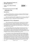
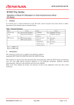
RENESAS TECHNICAL UPDATE TN-16C-A237A/E Date: Apr. 8, 2014 RENESAS TECHNICAL UPDATE 1753, Shimonumabe, Nakahara-ku, Kawasaki-shi, Kanagawa 211-8668 Japan Renesas Electronics Corporation Product Category Title MPU & MCU Document No. Deletion of Specifications and Errata for R32C/ 111 Group User’s Manual: Hardware Information Technical Notification Category TN-16C-A237A/E Rev. 1.00 Lot No. Applicable R32C/111 Group Product Reference Document R32C/111 Group User’s Manual: Hardware Rev. 1.20 (R01UH0209EJ0120) This document describes deletion of specifications and errata for the R32C/111 Group User’s Manual: Hardware, Rev. 1.20. 1. Deletion of Specifications Development of products on the planning phase in Table 1.7 is discontinued. Accordingly, specifications for the 80-pin package are deleted. The corresponding corrections to the manual are as follows: •Descriptions for the 80-pin package is deleted from chapter 1. •N version is deleted from the Operating Temperature row in Table 1.6. •Descriptions for the 80-pin package is deleted from Table 4.20. •Descriptions for the 80-pin package is deleted from Table 5.1. •Descriptions for the 80-pin package is deleted from section 7.1. •Descriptions for the 80-pin package is deleted from the first paragraph of chapter 15. •Descriptions for the 80-pin package is deleted from Figure 15.4. •Descriptions for the 80-pin package is deleted from section 16.3.3.1. •Descriptions for the 80-pin package is deleted from section 18.5.2. •Descriptions for the 80-pin package is deleted from Table 19.1. •Descriptions for the 80-pin package is deleted from the third bullet of section 19.3.1 •Descriptions for the 80-pin package is deleted from the first paragraph of chapter 20. •Descriptions for the 80-pin package is deleted from chapter 24. •Descriptions for the 80-pin package is deleted from chapter 25. •Descriptions for the 80-pin package is deleted from chapter 26. •Descriptions for the 80-pin package is deleted from chapter 27. •Dimension for the 80-pin package is deleted from Appendix 1. 2. Errata The corrections are indicated in red in the list below. • Page 1 of 493, expression “I2C” in line 9 of 1.1 is modified as follows: “I2C-bus interface” ©2014. Renesas Electronics Corporation, All rights reserved. Page 1 of 8 RENESAS TECHNICAL UPDATE TN-16C-A237A/E Date: Apr. 8, 2014 • Pages 2 and 6 of 493, expression “calculation transfer” and “chained transfer” in Tables 1.1 and 1.5 are modified as follows: “calculation result transfer” and “chain transfer” • Page 68 of 493, description in Note 4 of Figure 6.4 is modified as follows: “4. This bit can be set to 0 by a program (Writing 1 to this bit has no effect).” • Page 70 of 493, description of the third paragraph of 6.2.1 is modified as follows: “When the voltage rises to or above Vdet(R) again, the VMF bit becomes 1 (VCC Vdet) and the LVDF bit becomes 1.” • Page 78 of 493, bit name “XCIN-XCOUT Drive Power Select Bit” in Figure 8.3 is modified as follows: “XCIN-XCOUT Drive Strength Select Bit” • Page 79 of 493, bit name “XIN-XOUT Drive Power Select Bit” in Figure 8.4 is modified as follows: “XIN-XOUT Drive Strength Select Bit” • Page 119 of 493, typo “WR0” in Table 9.5 is corrected as follows: “WR” • Page 130 of 493, description “Bits PRC0 and PRC1 do not automatically become 0. They should be set to 0 by a program.” is deleted from Note 1 of Figure 10.1. • Page 135 of 493, the following description is added to 11.3.2: “Peripheral interrupts are maskable.” • Page 150 of 493, description “The following is the priority order of hardware interrupts” in lines 7 and 8 of 11.8 is modified as follows: “The following is the priority order determined by the hardware” • Page 159 of 493, the following description is modified in line 6 of chapter 12: “The watchdog timer has a prescaler which divides the peripheral bus clock by 16 or 128.” • Page 159 of 493, the following description is added to line 13 of chapter 12: “Depending on the timing of when a value is written to the WDTS register,” • Page 171 of 493, external bus address “00060000h” in Table 13.5 is corrected as follows: “00080000h” •Pages 176 to 184 of 493, expression “chained transfer” in chapter 14 is modified as follows: “chain transfer” •Page 176 of 493, description of chain transfer in Table 14.1 is modified as follows: “Data transfer is sequentially performed by switching among multiple DMAC II indexes (transfer information)” • Pages 178 and 179 of 493, expression “DMA II transfer complete interrupt vector address” in lines 3 to 4 and the seventh bullet point of 14.1.2 and Figure 14.2 is corrected as follows: “jump address for the DMA II transfer complete interrupt handler” • Pages 178 and 181 of 493, expression “interrupt vector” in Figure 14.2 and 14.1.4 is corrected as follows: “interrupt vector space” Page 2 of 8 RENESAS TECHNICAL UPDATE Date: Apr. 8, 2014 TN-16C-A237A/E • Page 179 of 493, expression “jump address” in the seventh bullet point of 14.1.2 is corrected as follows: “start address” • Page 184 of 493, descriptions in Figure 14.5 is modified as follows: “The figure below applies under the following conditions: memory-to-memory transfer; incrementing source address; non-incrementing destination address; single transfer mode; transfer complete interrupt generated after 2 transfers (transfer counter = 2); no chain transfer” • Page 190 of 493, description of the third bullet point of 16.1 is corrected as follows: “One-shot timer mode: The timer outputs a pulse after a trigger input until the counter reaches 0000h” • Page 195 of 493, typos “b2 b3”, “b4 b5”, and “b6 b7” in Figure 16.9 are corrected as follows: “b3 b2”, “b5 b4”, and “b7 b6” • Page 202 of 493, pin name “INT2” in Figures 16.13 and 16.14 is corrected as follows: “INT2” • Page 206 of 493, bit symbol “TAiS” in the Function column for the MR2 bit in Figure 16.16 is corrected as follows: “TAiOS” • Page 236 of 493, register symbol “INV1” in Note 2 of Figure 17.17 is corrected as follows: “INVC1” • Pages 239 to 291 of 493, terms in chapter 18 are corrected as follows: Before Correction receive register After Correction receive shift register transmit register transmit shift register SS function slave select function BRG restart condition UiBRG repeated START condition Figure/Table/Section Number Figures 18.1, 18.2, 18.21, 18.27 Tables 18.2, 18.5, 18.11, 18.14 Section 18.3.8 Figures 18.1, 18.2, 18.20, 18.21, 18.25, 18.26 Tables 18.2 (2 corrections), 18.3, 18.4, 18.5 (2 corrections), 18.6, 18.7, 18.10, 18.14 (2 corrections), 18.15 Section 18.3.8 (3 corrections) Figure 18.12 (3 corrections) Table 18.14 Sections 18.4.1, 18.4.1.1, 18.4.1.2 Table 18.8 (3 corrections) Figure 18.13 Table 18.10 Sections 18.3.2 (2 corrections), 18.5.4 Page 3 of 8 RENESAS TECHNICAL UPDATE Date: Apr. 8, 2014 TN-16C-A237A/E • Page 240 of 493, positions of “010” for bits SMD2 to SMD0 in Figure 18.1 are corrected as follows: RXD polarity switch circuit RXDi SMD2 to SMD0 CLK1 and CLK0 00 CKDIR UiBRG f1 register 01 0 1/16 1/(m+1) 1/16 f8 10 f2n 1 100, 101, 110 001, 010 Receive clock Transmit/ Receive control receive circuit TXD polarity switch circuit TXDi (1) unit 100, 101, 110 Transmit control circuit 001, 010 CKDIR Transmit clock 0 1/2 1 CKPOL CLK polarity switch circuit CLKi CKDIR Direction register CTSi/RTSi RTSi CTSi CRD m: Value set in the UiBRG register Note: 1. P7_0 (TXD2) is a pin for the N-channel open drain output. This pin cannot be set as push-pull output. IOPOL 0 1 RXDi SMD2 to SMD0 STPS SP 0 1 PRYE SP 001, 010 001, 101 0 PAR 1 b8 100, 101, 110 0 0 0 0 0 0 b6 b5 b4 b3 b2 b1 b0 D6 D5 D4 D3 D2 D1 D0 001, 010, 101, 110 010, 110 0 UARTi receive shift register 100 b7 D8 D7 UiRB register Logic inversion circuit + Bit order reverse circuit Upper byte of data bus Lower byte of data bus Logic inversion circuit + Bit order reverse circuit D8 STPS SP SP 0 1 PRYE 001, 010 0 PAR 1 D7 001, 101 b8 100, 101, 110 D6 D5 D4 D3 D2 D1 D0 b6 b5 b4 b3 b2 b1 b0 UiTB register 100 b7 010, 110 SMD2 to SMD0 SP: Stop bit PAR: Parity bit 001, 010, 101, 110 UARTi transmit shift register IOPOL 0 1 TXDi SMD2 to SMD0, STPS, PRYE, IOPOL, and CKDIR: Bits in the UiMR register CLK1, CLK0, CKPOL, and CRD: Bits in the UiC0 register Page 4 of 8 RENESAS TECHNICAL UPDATE Date: Apr. 8, 2014 TN-16C-A237A/E • Page 246 of 493, description in Function of the UiIRS bit in Figure 18.7 is modified as follows: “0: Transmit buffer is empty (TI = 1) • Page 250 of 493, expression “baud rate generator count source” in the function of bits DL0 to DL2 in Figure 18.12 is corrected as follows: “count source for the UiBRG register” • Pages 257, 258, 265, 266, 275, 285 of 493, descriptions in Function of the UiBRG register in Tables 18.3, 18.4, 18.6, 18.7, 18.10, and 18.15 are modified as follows: “Set the divide ratio according to the bit rate” • Pages 258, 266 of 493, description for (b7 to b4) to registers UiC1 and U78CON in Tables 18.4 and 18.7 is added as follows: “(b7 to b4) Set the bits to 0000b” • Page 259 of 493, waveform of the IR bit in Figure 18.20 is corrected as follows: Transmit timing (when selecting an internal clock) TC Internal transmit/ receive clock TE bit in the UiC1 register Data is set to the UiTB register Data is transferred from the UiTB register to the UARTi transmit shift register TI bit in the UiC1 register CTSi TCLK Pulse stops because the input level at the CTSi pin is high Pulse stops because the TE bit is set to 0 CLKi TXDi D0 D1 D2 D3 D4 D5 D6 D7 D0 D1 D2 D3 D4 D5 D6 D7 D0 D1 D2 D3 D4 D5 D6 D7 TXEPT bit in the UiC0 register IR bit in the SiTIC register Set to 0 by accepting an interrupt or by a program This figure applies under the following conditions: - The CKDIR bit in the UiMR register is 0 (internal clock). - The CRD bit in the UiC0 register is 0 (CTS function enabled). - The CKPOL bit in the UiC0 register is 0 (output transmit data on the falling edge of the transmit/receive clock). - The UiIRS bit in registers UiC1 and U78CON is 0 (an interrupt request is generated when the transmit buffer is empty). TC = TCLK = 2(m + 1)/fx fx: UiBRG count source frequency (f1, f8, or f2n) m: Value set in the UiBRG register Page 5 of 8 RENESAS TECHNICAL UPDATE Date: Apr. 8, 2014 TN-16C-A237A/E • Page 261 of 493, descriptions in 18.1.1 are modified as follows: “When a transmit/receive error occurs in synchronous serial interface mode, follow the procedures below to perform a reset: (1) Set the TE bit to 0 (transmission disabled) and the RE bit to 0 (reception disabled) in the UiC1 register (i = 0 to 8). (2) Set bits SMD2 to SMD0 in the UiMR register to 000b (serial interface disabled). (3) Set bits SMD2 to SMD0 to 001b (synchronous serial interface mode). (4) Set the TE bit to 1 (transmission enabled) and the RE bit to 1 (reception enabled) in the UiC1 register.” • Page 263 of 493, the following description is added to line 3 of 18.1.6: “after the last bit is transmitted” • Page 266 of 493, description for (b7) to the UiMR register in Table 18.7 is added as follows: “(b7) Set the bit to 0” • Pages 267, 268 of 493, description “Internal transmit/receive clock” in Figures 18.25 and 18.26 is corrected as follows: “Internal transmit clock” • Page 269 of 493, Figure 18.27 is corrected as follows: Example of data receive timing when the character length is 8-bit (parity disabled, 1 stop bit) UiBRG output RE bit in the UiC1 register RXDi Start bit D0 D1 D7 Stop bit Data reception starts when the receive clock is generated on the falling edge of the start bit Internal receive clock Low is reverified RI bit in the UiC1 register Input of receive data Data is transferred from the UARTi receive shift register to the UiRB register The UiRB register is read RTSi It becomes low when the UiRB register is read IR bit in the SiRIC register Set to 0 by accepting an interrupt request or by a program This figure applies under the following conditions: - The PRYE bit in the UiMR register is 0 (parity disabled). - The STPS bit in the UiMR register is 0 (1 stop bit). Page 6 of 8 RENESAS TECHNICAL UPDATE TN-16C-A237A/E Date: Apr. 8, 2014 • Page 270 of 493, descriptions in 18.2.2 are modified as follows: “When a transmit/receive error occurs in UART mode, follow the procedure below to perform a reset: (1) Set the TE bit to 0 (transmission disabled) and the RE bit to 0 (reception disabled) in the UiC1 register (i = 0 to 8). (2) Set bits SMD2 to SMD0 in the UiMR register to 000b (serial interface disabled). (3) Set again bits SMD2 to SMD0 to either of 001b, 101b, or 110b. (4) Set the TE bit to 1 (transmission enabled) and the RE bit to 1 (reception enabled) in the UiC1 register. • Page 273 of 493, descriptions for the Interrupt request generating timing in Table 18.9 are modified as follows: Interrupt request generating timing • START condition is detected • STOP condition is detected • ACK (acknowledge) is detected, or reception is completed • NACK (not-acknowledge) is detected, or transmission is completed • Page 275 of 493, description for (b6 to b4) to the UiMR register in Table 18.10 is added as follows: “(b6 to b4) Set the bits to 000b” • Page 291 of 493, description for suspending and resuming communication is added to 18.5.5 as follows: “18.5.5 Reset Procedure or Suspend/Resume Procedure Operations which result in communication errors such as rewriting function select registers during transmission/reception should not be performed. Follow the procedure below to reset the internal circuit once the communication error occurs in the following cases: when the operation above is performed by a receiver or transmitter or when a bit slip is caused by noise. Also follow the procedure below when suspending and resuming communication in an emergency.” • Page 304 of 493, description in the specification of the function in Table 19.6 is modified as follows: “The analog voltage applied to eight selected pins including one to four prioritized pins is repeatedly converted into a digital code. The prioritized pins are selected by setting bits SCAN1 and SCAN0 in the AD0CON1 register and bits APS1 and APS0 in the AD0CON2 register” • Page 369 of 493, descriptions of the first and second paragraphs in 24. I/O Pins are modified as follows: “Each pin of the MCU functions as a programmable I/O port, an I/O pin for integrated peripherals, or a bus control pin. These functions can be switched by the function select registers or the processor mode registers. This chapter particularly addresses the function select registers. For the use as a bus control pin, refer to 7. “Processor Mode” and 9. “Bus”. The pull-up resistors are enabled for every group of four pins. However, when a pin functions as an output pin, a pull-up resistor is disabled regardless of the register settings. • Page 369 of 493, description in the last paragraph of 26. I/O Pins is corrected as follows: “The input-only port P8_5 shares a pin with NMI and has neither function select register nor the corresponding direction bit. Port P9_1 also functions as an input-only port. The function select register and bit 1 in the PD9 register are reserved. Port P9 is protected from unexpected write accesses by the PRC2 bit in the PRCR register (refer to 10. “Protection”).” • Page 394 of 493, description “addresses: 03CAh, 03CBh” in Note 5 of Table 24.2 is modified as follows: “registers PD4 and PD5” Page 7 of 8 RENESAS TECHNICAL UPDATE TN-16C-A237A/E Date: Apr. 8, 2014 • Pages 394 and 395 of 493, description in Note 2 of Tables 24.2 and 24.3 are modified as follows: “When configuring as an output port to release the pin open, it remains as an input port until it is set as an output port after a reset is released. Therefore, while it remains as an input port, the power supply current may increase due to the undefined voltage level of the pin. In addition, the direction register value may change due to noise or program runaway caused by the noise. To avoid these situations, reconfigure the direction register regularly by software, which may achieve higher program reliability.” • Page 400 of 493, description “When the ID code protection is activated,” is deleted from line 1 of 25.2.3. • Pages 443 and 455 of 493, “TXD4”, “STXD4”, and “RTS4” are deleted from Note 1 of Tables 26.16 and 26.39. • Pages 444 and 456 of 493, expression “Drive power” in Tables 26.17 and 26.40 is modified as follows: “Drive strength” • Page 473 of 493, expression “drive power” in line 2 of 27.3.1.1 is modified as follows: “Drive strength” • Page 482 of 493, expression “restart condition” in line 1 of 27.9.4 is modified as follows: “repeated START condition” • Page 483 of 493, description for suspending and resuming communication is added to 27.9.5 as follows: “27.9.5 Reset Procedure or Suspend/Resume Procedure Operations which result in communication errors such as rewriting function select registers during transmission/reception should not be performed. Follow the procedure below to reset the internal circuit once the communication error occurs in the following cases: when the operation above is performed by a receiver or transmitter or when a bit slip is caused by noise. Also follow the procedure below when suspending and resuming communication in an emergency.” Page 8 of 8