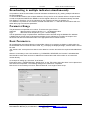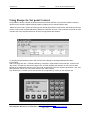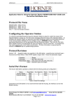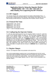
1
APP0392-01
14/07/00
KEEP WITH USER MANUAL
Using the TIU Terminal Range with a DATA TRACK TRACKER 240 series.
Note
This document assumes that all items have correct power applied, Cbreeze software is running a download
cable is connected between the computer and the TIU terminal and the correct cable is installed between
the TIU and the equipment being used.
Protocol Revisions
DATATRACKV1.05 or later -supports master only operation to the slave Weighing Indicator using a decimal
version of the MODBUS RTU protocol. Communication to the Weighing Indicator is via the PLC Port on the
TIU terminal and the appropriate screw terminals on the Inverter module.
The default settings are 9600 baud, eight data bits, no parity and one stop bit with no handshaking.
The connection is RS 422/485 communications. See attached drawings at the end of this document.
Correct Firmware
The TIU terminal will only communicate with the Weighing Indicator if it has the appropriate firmware has
been installed. The firmware installed will be displayed on the front screen of the terminal during “power
up”.
If new firmware needs installing the appropriate file for the terminal type is required i.e.
Tiu050 = DATATRACK_R?.0xx
Tiu1xx = DATATRACK_R?.1xx
Tiu2xx = DATATRACK _R?.2xx
? = The TIU firmware revision.
The easiest way to install the correct firmware into the TIU terminal is to carry out the following procedure: Select “Configure”/ “Terminal type”to select the TIU type and initialise all relevant parameters.
Select “Configure”/ “Communication Settings”and then select the “Manufacturer”and “Model”being used
and also check that Communication Mode, Baud Rates and that the correct Network and connection details
are all correct. (RS 422 / RS 485).
After all settings are confirmed as correct, select File / Update protocol. If the above has been completed
the computer should have selected the correct file to download. Accepting this option will automatically
initiate the protocol download to the TIU.
Initial Settings in the Datatrack 240.
In order to communicate to the Weighing Indicator, it is first necessary to set up some parameters from the
front panel of the DATATRACK 240.
CoNN will need to be set to Binary Modbus RTU.
Addr will need to match the address used in the configurator.
If a network is required then the Network Enable will need to set in “Configure / Communication Settings ”
and the appropriate address will then need to be added to each item of data that is embedded on the
screen.
Horner Europe Tel (+353) 21 4321266 e-mail [email protected]
Horner UK Tel (+44) 0870 8435363
Horner Electric APG Tel (+1) 317 916-4274 Fax (+1) 317 916 4287 www.horner-apg.com
Page 1 of 7
APP0392-01
Rtu
Baud
Prot
Prty
StoP
14/07/00
KEEP WITH USER MANUAL
should be set to ON
should be set to 0,1,2 03 3 to match the TIU. (1200, 2400, 4800, 9600). Default is 9600
should be set to OFF to allow changes via RTU communication.
should be set to 2 (none) with RTU communication.
should be set to OFF (1 bit) with RTU communication.
Node Addresses
The addresses of each device can range from 1 to 247 and the default address is 1
Networking several Indicators
The communication interface is RS422 and as such up to 32 Indicators can be connected together on to a
network. Each Indicator must have an individual address in a range 1 –247. Only 32 devices should be
included on a Network at any one time without repeaters. Using Repeaters is not within the scope of this
document.
The Network Option must be enabled from “Configure / Communication Settings / Network Mode Enable”.
RS 422 / RS485 option must also be selected. Cabling details are shown at the end of this document
Each item of embedded data will need to have the correct node address entered as part of the data set-up
screen to indicate which Indicator is to be accessed.
Also the data can be selected to be editable from the TIU and data scaling can be set-up to convert values
in the Indicator into engineering units. E.g. Indicator weight in Kilos to weight in imperial pounds.
The manual supplied with the DATATRACK 240 shows the register range and definitions.
An example is shown below on how to communicate to register 17CH on Node address 27.
Note that Node Addresses are in decimal, register addresses are hexadecimal in decimal in Modbus RTU
Dec.
Horner Europe Tel (+353) 21 4321266 e-mail [email protected]
Horner UK Tel (+44) 0870 8435363
Horner Electric APG Tel (+1) 317 916-4274 Fax (+1) 317 916 4287 www.horner-apg.com
Page 2 of 7
APP0392-01
14/07/00
KEEP WITH USER MANUAL
Broadcasting to multiple indicators simultaneously.
It is possible to send the same data to several Indicators simultaneously E.g. setting multiple Indicators to
the same setpoints.
To do this all data must be sent to Node Address 0. Every device on the network will then accept the data.
In order to implement WRITE then READ to confirm register values, the TIU will automatically read back
from Station 1 Therefore, one of the Indicators on the network must have an address of 1.
If no Address 1 is present on the network, the data field will show ***** and bad communications will occur
whilst still trying to access this parameter.
Parameter Range
The parameters are specified as a number. There are two types of data: Analogue
data returned in words of 16 bits e.g. 1 - the Displayed value.
Logic
data returned as simple bits e.g. 34 - UN-tare display.
The full parameter range is implemented. Addresses must be entered using the Modbus Dec address.
A detailed list of the full range of parameters available for this Indicator is not within the scope of this
document and reference should be made to the appropriate DATA TRACK manual.
Basic ParametersAll the addresses use Internal Words or Internal Bits. Where it is necessary to display a 16-bit value then
the embedded data for Words should be used. E.g. To display the displayed weight, Internal Word 2 should
be used.
Just “double click”at the place here data is to be added to a screen and select the required embedded data
type.
Where it is necessary to use a bit condition e.g. FORWARD / REVERSE, the “bit token”embedded data
field should be used. Data can then be added as an Internal Word with a bit number or an internal bit
number directly.
An example of setting up a “bit token”is as follows: Enter basic text e.g. DIRECTION then “Double click”on the TIU screen where the token is to be placed and
then select the bit operator. The following dialogue box needs to be completed.
Note that it is not necessary to enter a “Remote Node ID”on a single Inverter set-up.
Horner Europe Tel (+353) 21 4321266 e-mail [email protected]
Horner UK Tel (+44) 0870 8435363
Horner Electric APG Tel (+1) 317 916-4274 Fax (+1) 317 916 4287 www.horner-apg.com
Page 3 of 7
APP0392-01
14/07/00
KEEP WITH USER MANUAL
Using Recipe for Set point Control
It is possible to set-up a simple recipe structure that will allow selection of an item and load the relevant
values into the set point registers 236 and 238 by mapping SP1 to 236 and SP2 to 238.
Select the “Chef’s Hat”symbol and overtype the default page with the required text. Obviously the Record
column could contain a sequential table of data that could start at Level 1 and increment to level N for more
complex use of the set point feature or where more ingredients are needed.
To simplify using and setting up the TIU screens for the Recipe’s, two Page Wizards have been
incorporated.
Add a new page with the + ICON and selecting “Configure / Page Wizard / Select Recipe “and fill in the
“Use Field”. This will then structure a page on the TIU that will allow the selection of one of the records
(based on the parameter entered in the “Use Field”box) and send it to the set point parameters. The “Use
field”selection can be any of the items shown in the “Field”column.
The values within a record can be entered from the configurator by clicking on the required cell.
Horner Europe Tel (+353) 21 4321266 e-mail [email protected]
Horner UK Tel (+44) 0870 8435363
Horner Electric APG Tel (+1) 317 916-4274 Fax (+1) 317 916 4287 www.horner-apg.com
Page 4 of 7
APP0392-01
14/07/00
KEEP WITH USER MANUAL
When configured the Recipe selection page will look something like the example shown above.
• Press SEL to initiate selection of the product.
• Press NEXT or PREV to select the Record or item in the “Use Field”box.
• Press SEND to send the data.
Editing a Recipe
If it necessary to edit the parameters from the TIU, then 2nd Page Wizard will need to be used.
Add a new page with the + ICON and selecting “Configure / Page Wizard / Edit Recipe “ and fill in the “Use Field”.
This will then structure a page on the TIU that will allow the selection of one of the records (based on the parameter
entered in the “Use Field” box) and then to select individual cells within the record and to edit this cell from the TIU
keyboard.
•
•
•
•
•
Press SEL to initiate selection of the product.
Press NEXT or PREV to select the Record or item in the “Use Field” box.
Press EDIT to select the first record.
Press EDIT to step to the correct field for editing.
Press Up and Down to change data (or use numeric keys) if available.
Horner Europe Tel (+353) 21 4321266 e-mail [email protected]
Horner UK Tel (+44) 0870 8435363
Horner Electric APG Tel (+1) 317 916-4274 Fax (+1) 317 916 4287 www.horner-apg.com
Page 5 of 7
Using the TIU Terminal Range with a DATA TRACK TRACKER 240 series
120R Resistor to be connected
at furthest point from the master device
TIU 100/110
+5V
TX 485/422+
TX 485/422RX 485/422+
RX 485/422TX RS232
0V (GND)
RX RS232
TX 20mA +
TX 20mARX 20mA+
RX 20mAEARTH
Twisted Pairs
Rs422
1
2
3
4
5
6
7
8
9
10
11
12
13
RA - 12
RB - 13
TA - 10
TB - 11
120R Resistor to be connected
at furthest point from the master device
Rs485
TIU 100/110
+5V
TX 485/422+
TX 485/422RX 485/422+
RX 485/422TX RS232
0V (GND)
RX RS232
TX 20mA +
TX 20mARX 20mA+
RX 20mAEARTH
Twisted Pair
1
2
3
4
5
6
7
8
9
10
11
12
13
RA - 12
RB - 13
TA - 10
TB - 11
Configuration Bank
Switch
1
2
3
4
ON
Pull-up
120 termination
Pull-down
Reserved for future use
OFF
No Pull-up
No termination
No Pull-down
Use Belden or equivalent twisted pair cable.
The 120R resistor should be fitted on the
last node on the network.
NOTE: Switch 1 and 3 must be used together.
OFF
ON
4
3
2
SW1
1
Page 6 of 7
Using the TIU Terminal Range with a DATA TRACK TRACKER 240 series
TIU 50/101/102/
111/112/20X
120R Resistor to be connected
at furthest point from the master device
Twisted Pairs
TX 485/422+
TX 485/422RX 485/422+
RX 485/422TX RS232
0V (GND)
RX RS232
SHIELD
Rs422
RA - 12
RB - 13
TA - 10
TB - 11
1
2
3
4
5
6
7
8
120R Resistor to be connected
at furthest point from the master device
TIU 50/101/102/
111/112/20X
Rs485
Twisted Pair
TX 485/422+
TX 485/422RX 485/422+
RX 485/422TX RS232
0V (GND)
RX RS232
SHIELD
RA - 12
RB - 13
TA - 10
TB - 11
1
2
3
4
5
6
7
8
Configuration Bank
Switch
1
2
3
4
ON
Pull-up
120 termination
Pull-down
Reserved for future use
OFF
No Pull-up
No termination
No Pull-down
Use Belden or equivalent twisted pair cable.
The 120R resistor should be fitted on the
last node on the network.
NOTE: Switch 1 and 3 must be used together.
OFF
ON
4
3
2
SW1
1
Page 7 of 7