1
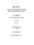
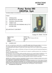
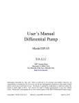
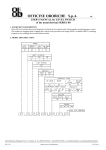
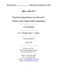
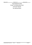
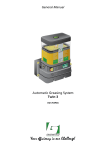
BOSfluids Tutorial Getting Started The “Getting Started” tutorial guides the user through the process of building a model, defining boundary conditions and the basics of postprocessing. This tutorial is designed for people who are not familiar with the software and shall demonstrate the basic features. BOSfluids Getting Started 1. CONSTRUCTING THE MODEL 1.1. Introduction The following system will be used to demonstrate the use and some of the basic features of the transient fluid flow simulation package BOSfluids®. The example consists of a simple water evacuation system that is 80 meters long and has a gate valve at the end that closes in 0.5 seconds. The steel piping has a roughness = 0.05 mm. The analysis should predict the pressure rise in the system upon valve closure. Figure 1 | Example of a water evacuation system 1.2. Starting the program and creating a new model Start the program BOSfluids. Using the New Job button, a new model can be created. Name the new model GetStarted and select Metric in the unit selection box. If a model has already been created, use the Open Job button and select the file (with extension .bfz). Figure 2 | BOSfluids Start-up screen When the program has opened, it shows the first tab; Piping. Here the piping layout can be entered one element at a time. Another possibility is to import an existing piping layout Copyright © Dynaflow Research Group. Page 1 of 16 BOSfluids Getting Started from a pipe stress software package such as CAESAR II, or from a previous version of BOSfluids. Import features are discussed in other tutorials. The construction procedure of the model, depicted in Figure 1, will be described in detail in this tutorial. During entry of data, the user can get help by pressing Shift + F1, or selecting Help What’s This? from the toolbar and select the input field of interest. To enter the first element, press the “create new element” icon, +. Set the element type to Pipe in the input screen. This changes the dynamic input screen, to show the required input parameters applicable to this element type. Fields that are still required to be filled out are displayed in red. Change the first node number to 5 and the second node number to 10. Now, create a 40m long pipe in the negative Z-direction with diameter 250mm, wall thickness 5mm and pipe roughness 0.05mm. The input data for pipe material, pipe restraint and fluid temperature can be left at their default values, see Figure 3. Click Apply Changes, or press enter to confirm the input. Figure 3 | Input screen for the first element Figure 4 | Input screen for the second element Now create the second element by clicking the + button. The element type is now set automatically to the previous Pipe element. Change the second node number to 15 and create a 40m long pipe element in the X-direction. The element parameters are the same as defined in the first element and can be left unchanged. Page 2 of 16 Copyright © Dynaflow Research Group. BOSfluids Getting Started At node number 10 there is a bend in the pipe system. This can be easily incorporated by ticking the Bend box next to Node 1, see Figure 4. When navigating through the elements using the arrows at the top of the tab, it can be seen that node number 10 in the first element is now also assigned to be a bend. Figure 5 | Input screen for the third element Figure 6 | Input screen for the fourth element The third element is of type Valve and is 0.5m long in the X-direction, see Figure 5. Select Valve from the Type drop down menu, set the Valve Bore to 230mm and the Discharge Coefficient to 0.5. Check that the option Steady State Valve Opening is set to 100%, to have the valve fully open during steady state analysis. Each element can also be given a Name. This is especially useful for special components like pumps, valves, etc. BOSfluids generates default names for all elements other than piping element. Name the valve element V_Shutoff. Transient actions such as a valve closure are found under Transient Valve Actions. By double clicking the … button next to Valve Actions, the valve opening as function of time can be entered. For this example, the valve closes linearly from 100% open at time 0 seconds to fully close (0% open) at time 0.5 seconds, see Figure 7. By default the flow coefficient, which determines the resistance the flow experiences when passing through the valve (resulting in a pressure loss over the valve), varies linearly with the valve opening. For this case the flow coefficient at 100% opening is specified by the Copyright © Dynaflow Research Group. Page 3 of 16 BOSfluids Getting Started Discharge Coefficient and has a value of 0.5. Using the Configure Valve window the flow coefficient can also be specified by giving a Cv or Kv value. Also a custom valve curve can be specified, but in this example we keep these settings as default. Figure 7 | Valve Action screen Finally add the last element again of type Pipe. Change the second node number to 25 and create a 0.5m long pipe element continuing in the X-direction. The element parameters are the same as defined in the other pipe elements, see Figure 6. The basic construction of the piping model is now finished. The Edit menu or right clicking the piping model in the 3-D viewer provides all kinds of options to insert delete or split elements when required. 1.2.1. Units Different sets of units can be selected. At the top of the screen, go to Tools -> Units and select the preferred type of units. English units as well as SI units are available. Switching units can be done at any time; at the start of a model but also during the modeling or even at the analysis phase. 1.2.2. Visualization The model is depicted in the 3D Visualization Screen. The view can be altered by using the buttons Pan, Rotate, Zoom and Center at the top of the visualization screen. Because the length of pipe elements can be very large compared to the diameter, details like valves might be difficult to view. A useful tool is the Diameter Multiplier, which can be found by clicking the visualization settings button at the top-right of the visualization screen . Setting this to a larger value makes components and details in the routing, like bypasses or loops, more visible. Depending on your screen resolution, set the Diameter Multiplier to a larger value, for example 5. Pressing the show labels button Page 4 of 16 will show the node numbers and element Copyright © Dynaflow Research Group. BOSfluids Getting Started names (where used). The model should now look like Figure 8. The user can also select to view the model as a Wireframe or select Search to look for a specific node or element. The measurement tool can be used to show the absolute distances between two nodes and also shows the shortest possible path between them. Figure 8 | The model shown in the visualization screen including name/node tags 2. DEFINING THE PARAMETERS Switch to the second tab: Scenarios. In this tab the parameters for the simulation are specified. The parameters are specified for at least one scenario: Main. This is the base scenario and all simulation parameters need to be specified for this scenario. However, the user can also generate additional scenarios by applying small changes to the main scenario, without the need to create multiple variations on the same model in separate files. In this way, small variations can be easily analyzed without losing track of the main scenario. Note that when multiple scenarios are created the Main scenario will serve as a basis for all other scenarios. Changes made to the Main model, will propagate through to all the scenarios, overwriting the corresponding values in each scenario. This prevents the need to alter all the scenarios if a major change is required. The Main scenario can therefore not be deleted. 2.1. Element Parameters In the first sub-tab Elements, the element parameters are defined. For each element all parameters including the element type can be altered. The element parameters for the Main scenario can also be adjusted in the Piping tab. Elements can be made part of an element group. Element groups are created automatically per element type; all piping elements are added to element group Pipe, all valves are added to element group Valve, etc. Element groups can also be created manually by clicking the + button at the bottom of the Element Groups list. An element can be made part of more than one group. Copyright © Dynaflow Research Group. Page 5 of 16 BOSfluids Getting Started For larger systems, a smart use of element groups makes it very easy to change the input data at a later stage of a project. The element groups allow for quick input data manipulation by selecting an Element Group and then selecting all or some different elements in the Elements list. In the dynamic input screen the input parameters appear that are applicable to all elements. For example, when pipe elements are selected, all input fields that contain the pipe parameters appear. Changing a parameter in the dynamic input screen will apply the new value to all selected elements. When different types of elements are selected, only those parameters appear in the dynamic input screen that are common to all selected element types, except when the option Show All Fields has been enabled. 2.2. Node properties and boundary conditions In the sub-tab Nodes & BCs, various node properties can be entered. By selecting a node in the Nodes list on the right, it is possible to change the Node Type and the node properties. Selecting Node 10 in this example will show that the Node Type is Bend. The Bend Radius parameter can be changed here. The default value is 1.5 times the pipe diameter. For the current example, this value is correct. Similar to the elements and element groups, all nodes are automatically placed in a Node Group based on the node type. When selecting a node group in the Node Groups list all nodes belonging to that group are shown in the Nodes list. Again it is also possible to manually create a group. Make a new group by selecting nodes 5, 10 and 15 and clicking the Add To Group button, see Figure 9. An Add To Group window will appear, with all custom groups shown. The user can create a new group by selecting the +. Name the group PipeNodes and optionally provide a brief description. 2.2.1. Defining boundary conditions The system is subjected to the following boundary conditions: fixed reservoir pressure of 10 barg at node 5 open-end atmospheric pressure of 0 barg at node 25 Note: All pressures entered are gauge pressures, i.e. overpressures with respect to the ambient pressure. The entered pressure should not include any pressure due to fluid elevation. Enter the boundary conditions by clicking node group All, followed by clicking node 5. Now, choose Node Type = Fixed Pressure. At the dynamic input screen, enter 10 barg as the prescribed pressure, see Figure 10. Do the same for node 25 and enter 0 barg. Page 6 of 16 Copyright © Dynaflow Research Group. BOSfluids Getting Started BOSfluids has now created a Node Group Fixed Pressure. All nodes with fixed pressure boundary conditions will be automatically added to this group. Switching to this group will show both node 5 and node 25. To remove a boundary condition from a node, select the node and change the Node Type to Simple. Simple is the default node type, indicating that no boundary condition is defined at that node. Figure 9 | Create a custom Node Group by selecting Figure 10 | Create boundary conditions at Node 5 nodes and clicking the Create Group button and 20 Boundary conditions can be provided either as pressure or as flow rate, but to create a solvable solution the pressure must be specified at least one location. 2.3. Setting up an analysis At the sub-tab Analysis, the analysis type can be selected. This can be Steady State, Transient, Transient VCM, or Transient CAP (the last two include a cavitation model). Based on the selected analysis type, the dynamic input screen shows parameters that can be set for this analysis. A description of each parameter can be obtained by using the Help function or by consulting the User Manual. For the current example, select Analysis Type Transient and keep Fluid Type Water. All other parameters can be kept at their default values, see Figure 11. Copyright © Dynaflow Research Group. Page 7 of 16 BOSfluids Getting Started Figure 11 | Input screen for Analysis 2.3.1. Initial flow conditions Before a transient analysis is performed, the program needs to know the initial flow conditions. Typically a transient analysis is performed using the results of a steady state analysis as initial flow conditions, but there is also an option to start the transient analysis from a no-flow state. For the first case, the steady state analysis is automatically performed before the transient analysis is performed. 2.4. Scenarios As explained at the beginning of this section, different scenarios can be created by applying small changes to the main model. For the current example, we include a scenario which uses a higher pressure boundary condition. Click on the menu icon , or select Tools Scenarios from the window toolbar. A Scenarios window will appear, currently showing only Main. By clicking the add a new scenario icon, +, the user can add a new scenario. Name this scenario Higher Pressure and press OK. Now multiple scenarios can be selected. Adding a new scenario by using +, will make a copy of the main scenario. In the Scenarios window also other scenarios can be copied or the differences between two scenarios can be shown. Select the Higher Pressure Scenario. For the new scenario element, node and analysis properties can be changed. However, it is not possible to change the geometry of the model. Go to the sub-tab Nodes & BC and change the boundary condition at Node 5 to be 15 barg, see Figure 12. The model is now ready to be run. Page 8 of 16 Copyright © Dynaflow Research Group. BOSfluids Getting Started 3. RUNNING THE SIMULATION Go to the tab Run. The scenarios for which a run must be performed can be selected from the Scenario List. Tick both scenarios and click the run button, indicated in Figure 13. Any relevant messages, like errors or warnings, found in the model during a run, appear at the Messages section and the runs that have been completed appear in the list Completed. Figure 12 | Create a custom second Scenario, where Figure 13 | Start the simulation and run both the pressure at Node 5 is higher scenarios 4. REVIEWING THE RESULTS Select the tab Results. Here the output of the simulation can be reviewed. The results can be reviewed in the 3-D viewer, where the complete system can be shown for each time step. The results can also be shown as 2-D plots, in which the fluid properties per node or element are shown versus time. When performing a steady state analysis there is no variation in time. This means that the 3-D output is limited to time = 0 and no 2-D output is available. 4.1. 3-D Output Under the Heading 3-D Output, the user can select the scenario of interest and choose from the various data sets; Flow Rate, Force, Max Pressure, Pressure and Velocity. The selected data set is directly plotted in the 3-D viewer. To review the results through time, the slider can be Copyright © Dynaflow Research Group. Page 9 of 16 BOSfluids Getting Started used, a time location can be entered, or the results can be played automatically by clicking the Animate button speed button . The speed of the animation can be changed using the Set the animation . When the time is set at 0 seconds the values shown correspond with the steady state solution. The minimum and maximum values for the whole simulation can be shown in the 3-D viewer by selecting this option under the Configure Output Settings button . The values themselves can be shown using the Data Set information button. 4.1.1. Profile plot A profile plot can be generated by clicking the button. A first and last node needs to be entered and the selected variable in the Data Set is plotted along the length of the piping. Note that when entering a first and last node, the user needs to select a unique flow path. For flow paths with loops, the program will return a message that no logical graph output is possible. The Profile plot and the 3-D graphical results can be viewed simultaneously. When using the slider or the Animate button, both the 3-D Visualization and the Profile plot vary through time in a synchronous way. Alternatively also a Min-Max plot can be generated that shows all nodes arranged based on their minimum and maximum values 4.2. 2-D Output Under the heading 2-D Output, users can select a data set of interest and plot this for selected points of interest within the system. The available data sets depend on the type of element/node. Nodes – For individual nodes, you can plot Flow Rate, Force, Max Pressure, Pressure and Velocity. Node groups – For groups of nodes, you can plot the same variables as for individual nodes. The names of the group correspond with the groups specified in the BCs and Nodes sub-tab. Element – For all element types different than the pipe element, you can plot the variables of interest. For example, for a valve, you can plot Flow Rate, Opening and Pressure Drop. Element groups – For groups of elements, you can plot the same variables as for individual elements. The group name corresponds with the groups specified in the piping sub-tab. Page 10 of 16 Copyright © Dynaflow Research Group. BOSfluids Getting Started The selected variable is plotted against time (or frequency) on the horizontal axis. When plotting groups of nodes or elements, the results for each node or element in the group are plotted on a single graph. The plot type can be changed from Time Domain to Frequency Domain to show a frequency breakdown of the selected variable. 4.3. Interpretation of the results In the 2-D Output select Node Group PipeNodes, tick the Main scenario and Pressure data set, and click plot. The transient variation in the pressure at nodes 5, 10 and 15 is shown in Figure 14. Figure 14 | Results for the Pressure variation through time for each pipe node In Figure 14, two results stand out. The first result that should be noticed when studying Figure 14 is the negative pressures that are reached after 0.6 seconds. The unphysical negative pressures (full vacuum is equal to -1 barg) occur when an expansion wave progresses through the fluid. In reality vapour formation and column separation will occur when the line pressure drops below the fluid vapour pressure. The second result to notice in Figure 14 is that the results are only shown until 0.7 seconds, while the interesting period is longer. To solve these issues we need to go back to the tab Scenarios. 4.3.1. Redefining the analysis parameters BOSfluids can include the effect of vapour formation by selecting the Concentrated Air Pocket (CAP) cavitation analysis model. Return to the Main scenario and select the sub-tab Analysis. Set the Analysis Type to Transient CAP from the drop down menu. This analysis type will include the effect of cavitation and Copyright © Dynaflow Research Group. Page 11 of 16 BOSfluids Getting Started vapor formation in the simulation. The change in the Main scenario will also update the Higher Pressure scenario. Extra CAP options are now available. The CAP options require the parameter for Void Fraction to be filled out. This parameter represents the volumetric fraction of gas for the Reference pressure conditions (leave this at Atmospheric Pressure for this example). Use the value 5.5·10-6 for this parameter, see Figure 15. The program uses the Void Fraction to model the growth and collapse of gas bubbles in the liquid. The CAP model prevents the pressure to drop below vapour pressure and includes the possibility of pressure spikes due to bubble collapse. The end time of a simulation is by default determined automatically based on the system properties and transient actions. In some cases the interesting events may take place after the transient actions are finished. For these cases the end time can also be set manually. Under Transient options change the Simulation Time to 5 seconds. This allows the pressure pulsations originating from the valve closure to reach the end of the system and reflect back into the direction of the valve. Rerun the simulation for this new analysis model as before by going to the tab Run. Figure 15 | Input screen for a transient CAP analysis Page 12 of 16 Copyright © Dynaflow Research Group. BOSfluids Getting Started 4.3.2. Results for the transient CAP analysis In the tab Results the results for the transient pressure variation can be studied again in the 2-D Output, see Figure 16. Figure 16 | Results for the Pressure variation through time for the transient CAP analysis Reviewing Figure 16, the results look better this time. At the moment where the pressure in Figure 14 dropped below the vapour pressure (after 0.6 seconds), the pressure now remains constant at -0.99 barg (0.01 bar above vacuum). Also the longer simulation shows more of the transient events taking place after the valve is completely closed. The user is able to interact with the plotted results. By clicking on or in the vicinity of a data point, the value of the selected data point is displayed. Similarly, using a click and drag movement, the user can create a view window to zoom into the selected region (return to initial view by double clicking inside the plot area). Likewise, the legend can be moved to a different location, by clicking and holding the legend and dragging it across the plot. To change the settings of the plotted results, select View Settings, or click the settings button . Several options are available to adjust the display of the plot including; title, range of the axes, labels, and plot style. To export the plot or results, select File Save As, or click the button . The user is able to select a variety of different file type, to either export the figure or the data set. Select the file extension PNG Image, and save the file in the current working directory with the file name PressurePlot. To see the effect of a higher inlet pressure on the transient flow rate, select Node and enter 10 in the 2-D Output and plot the Flow Rate for both scenarios. Go to Settings and change the range of the x-axis to 1 second. The results should look like Figure 17. It can be seen that for Copyright © Dynaflow Research Group. Page 13 of 16 BOSfluids Getting Started both scenarios the flow rate becomes negative (back flow) shortly after the valve completely closes. After 0.7 seconds the wave front reflected from the BC at node 5 passes node 10 to increase the flow rate again. Figure 17 | Results for the Flow Rate variation at node 10 through time for both scenarios Results for the flow rate through the valve can be reviewed at 2-D output by selecting Element, V_Shutoff and plotting the Flow Rate and Opening for the Main scenario. As expected, the flow rate decreases in time while closing the valve, see Figure 18. Figure 18 | Results for the Flow Rate through the valve and the Opening while closing Page 14 of 16 Copyright © Dynaflow Research Group. BOSfluids Getting Started 5. THEORETICAL BACKGROUND The transient behaviour of a system as discussed in this example, depends on the specific acoustic response time of the system and the duration of the transient event. When the duration of the transient event is much larger than the response time, the system will respond in a "slow" or pseudo-static mode. When the transient event duration is less than the response time, the system will respond in a "fast" or dynamic mode. The system acoustic response time can be found from the approximate expression: 2L/c Where L is the distance from the source of the disturbance to the point in the piping system where the disturbance will be reflected, and "c" is the speed of sound in the fluid. For rough estimates of the response time in liquid filled pipes c may be taken as 1000 meters/second (approximately 3000 feet per second), and the basic system acoustic response time can be found from: L / 500 [sec.] with L in meters or: L / 1500 [sec.] with L in feet The system acoustic response time for the example can be found from: time = (2 x 80 m) / (1000 m/s) = 0.16 seconds. The transient event duration in the example is 0.5 seconds, which is larger than the system response time, so "slow" responses will be observed. The increasing pressure wave will return to the source and begin cancelling further increases before the full value of the surge pressure will be applied to the system. This phenomenon can also be experienced in a household when a water tab is shut quickly. Then a resounding "water hammer" is heard in the pipes. But when the water tab is slowly closed, there is hardly a whisper. The maximum pressure rise that could occur in any system due to a theoretical "instantaneous" valve closure is: pressure rise = (fluid density)(c)(V) Where (c) is the speed of sound in the fluid, and (V) is the initial velocity of the fluid. BOSfluids calculates the initial velocity of the fluid in the steady state solution. For the example, analyzed above the initial velocity is 14 meters/sec. Copyright © Dynaflow Research Group. Page 15 of 16 BOSfluids Getting Started Instantly stopping this flow would produce pressure rises in the order of: pressure rise = (1000 kg/m3)(1000 m/s)(14 m/s) = 14,000,000 N/m2 This is equivalent to 140bar. The BOSfluids calculation showed a maximum pressure rise in the system of 100bar, which is less than the theoretical pressure rise for an instantaneous valve closure, but still considered large. This is due to the relative fast closure of the valve (even though the system was considered “slow” in terms of response time) and the large velocity. To considerably reduce the pressure rise for this system a larger valve closure time should be applied. A more realistic value for this typical example would be a valve closure time of 10 seconds. Page 16 of 16 Copyright © Dynaflow Research Group.