1
IRSC Zone
Ducted Air-Conditioner Zoning IR Controller
(1-8 Zones)
Application program version: [1.8]
User manual edition: [1.8]_a
www.zennio.com
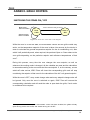
U SER MANU AL
ZN1CL-IRSC
IRSC Zone
Contents
Document Updates ................................................................................................................... 3
1
2
Introduction ...................................................................................................................... 4
1.1
The IRSC Controller .................................................................................................... 4
1.2
IRSC Zone .................................................................................................................. 4
1.3
Installation ................................................................................................................ 5
Configuration .................................................................................................................... 7
2.1
3
General Concepts ...................................................................................................... 7
ETS Parametrization .......................................................................................................... 9
3.1
Default Configuration ................................................................................................ 9
3.2
General.................................................................................................................... 11
3.3
Mode....................................................................................................................... 14
3.4
Fan .......................................................................................................................... 16
3.5
Temperature ........................................................................................................... 17
3.6
Thermostat.............................................................................................................. 20
3.7
Reset ....................................................................................................................... 21
Annex I. Installation Diagram .................................................................................................. 23
Annex II. Grille Control ............................................................................................................ 24
Switching the Zones On / Off............................................................................................... 24
Thermostatic Control for Cooling ........................................................................................ 25
Thermostatic Control for Heating ........................................................................................ 26
Annex III. Practical Example .................................................................................................... 27
Annex IV. Communication Objects .......................................................................................... 29
http://www.zennio.com
Technical Support: http://zennioenglish.zendesk.com
2
IRSC Zone
DOCUMENT UPDATES
Version
Modifications
Page(s)
Changes in the application program:
- Compatibility with additional remote controls.
-
- Revision of texts.
[1.8]_a
New structure in sections “Introduction” and “Configuration”.
Update of the Communication Object Table.
General revision of texts and styles.
4-8
29
-
Changes in the application program:
- New parameter added (“Zone Update After Reset”) to
allow sending read requests for the states, modes and
zone setpoints after bus failures.
- Revision of texts and parameter names.
- Function added to let the device store the current mode
on bus failures even if the machine was off.
[1.7]_a
- Inversion of the order of certain read requests sent after
reset, in order to avoid unexpected behaviours of the
device (such as when both the normal mode and the
extended mode read requests receive a response).
-
- Implementation of the temperature restriction even when
the machine is off, not only when it gets switched on.
- Reset of the variables of the PI control algorithm when
power failures occur.
Changes in the application program:
[1.6]_a
Option added to send read requests of certain objects to the
bus in order to recover the state of the device after a
download or a device reset from ETS.
http://www.zennio.com
-
Technical Support: http://zennioenglish.zendesk.com
3
IRSC Zone
1 INTRODUCTION
1.1 THE IRSC CONTROLLER
The IRSC controller from Zennio allows controlling electronic appliances with built-in
infrared receivers (such as air-conditioning systems, ducted climate units, audio/video
systems…) by emulating their IR remote controls.
Three alternate application programs are provided:
IRSC Plus, for controlling Split units.
IRSC Open, for controlling A/V devices.
IRSC Zone, for controlling ducted Cool/Heat units with support for climate
zoning.
1.2 IRSC ZONE
The IRSC Zone application allows controlling air cooling/heating ducted machines,
and particularly up to 8 rooms (or zones) where the air output is regulated by gates or
motorised grilles. Grilles are the final elements of the air ducts that distribute the air
flow from the central unit to every zone.
IRSC Zone is therefore in charge of two complementary functions:
Sending the necessary orders (ON/OFF, temperature, fan, etc) to the central
air-conditioning machine through infrared commands.
Sending the KNX bus open/close orders for the external actuators that control
the air grilles of the different climate zones.
In addition, IRSC Zone offers compatibility with most air conditioning manufacturers
(please refer to the Correspondence Table, available at http://www.zennio.com).
http://www.zennio.com
Technical Support: http://zennioenglish.zendesk.com
4
IRSC Zone
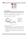
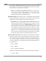
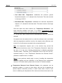
Figure 1. The IRSC Controller
1.3 INSTALLATION
The IRSC controller connects to the KNX bus via the corresponding bus terminals.
Once the controller is provided with power from the KNX bus, both the physical
address and the associated application program may be downloaded.
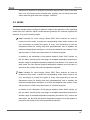
The element diagram of IRSC is shown in Figure 2.
1.- KNX Connector.
2.- Programming LED.
3.- Programming Button.
4.- Aerial Connector.
5.- IR Emitter.
6.- Socket for the Aerial
Figure 2. IRSC Element diagram
These elements are described next.
Programming Button (3): a short press on this button sets the device into the
programming mode, making the associated LED (2) light in red. If this button is
held while plugging the device into the KNX bus, IRSC enters the Safe Mode.
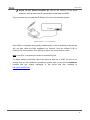
IR Emitter (5): infrared flashing diode to send commands to the air
conditioning system. It must be placed in front of the IR receiver of the A/C unit
(see Figure 3).
http://www.zennio.com
Technical Support: http://zennioenglish.zendesk.com
5
IRSC Zone
Socket for the Aerial Connector (6): slot for the insertion of the aerial
connector, through which the IR commands are outputted from IRSC.
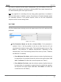
Figure 3 shows how to locate the IR Emitter (5) in front of the climate system.
IR receiver
Figure 3. IRSC - A/C unit interface
Once IRSC is connected and properly parameterised, it will be possible to operate the
A/C unit from within the KNX installation (for instance, from the InZennio Z38i or
InZennio Z41 touch panels), thus offering an easier and more intuitive control.
Note: one IRSC is required per ducted air-conditioning unit.
To obtain detailed information about the technical features of IRSC, as well as on
security and on the installation procedures, please refer to the device Datasheet,
bundled with the original packaging of the device and also available at
http://www.zennio.com.
http://www.zennio.com
Technical Support: http://zennioenglish.zendesk.com
6
IRSC Zone
2 CONFIGURATION
2.1 GENERAL CONCEPTS
The IRSC Zone application program permits controlling air-conditioning systems from
different manufacturers as if they were being controlled through their own infrared
remote controls.
A correspondence table is available at the Zennio homepage (http://www.zennio.com)
with the codes (from 0 to 255) corresponding to the different remote controls that can
be emulated. This number is the first parameter to be set in ETS, so that the orders
sent by IRSC become particularised for the actual A/C unit to be controlled.
The IRSC Zone application also allows selecting the number of zones that will be
controlled by the same central A/C machine, which can be 1 – 8.
Moreover, the following functions of the A/C system can be controlled by IRSC:
Switching ON/OFF each of the enabled zones.
Temperature Setpoint of each enabled zone.
Working Mode: the desired working mode (Automatic, Heat, Cool, Fan, Dry)
may be chosen through independent binary objects (one per mode) or through
a sole object (only one object for the mode selection). Moreover, apart from
these conventional controls, it is possible to enable a simplified control, which
only permits commuting from Heat to Cold and vice versa.
Fan Speed: step-controlled or through a precise control.
Thermostat: it is possible to enable and configure this functionality for the
Heat mode, the Cool mode, or both.
The central machine is controlled by taking into account the number of the zones to be
acclimatised, as well as their own setpoints:
http://www.zennio.com
Technical Support: http://zennioenglish.zendesk.com
7
IRSC Zone
The IRSC Zone application program calculates the temperature setpoint
that the central machine needs to be sent depending on what the desired
temperatures for the different zones are.
It is optionally possible to make this calculation also depend on an additional
feedback temperature, provided by a KNX sensor located next to the air flow
that returns to the machine, thus making it possible to correct undesired
switch-offs or adjustments made by the machine itself when it detects that the
ambient temperature of its actual location (which may be subject to punctual
heat or cold sources) is similar to the setpoint, although the ambient
temperatures of the zones are not.
Moreover, this calculation will also consider the “additional temperature”, if
parameterised with a value other than zero (see Section 3.5).
Apart from sending temperature setpoints and other orders to the air machine, IRSC is,
as already stated, responsible for controlling the air grilles of the zones, which
implies selecting and applying an algorithm which, depending on the setpoint and
reference temperatures of every zone, will continuously determine whether the grille of
each zone must stay open or not.
The independent control of these grilles makes it possible, in short, that a sole machine
with a unique temperature setpoint serves each of the zones as convenient, no matter
if the temperature setpoints of the zones are different.
All the concepts mentioned so far are explained in detail in section 3. For further details
and for a complete example, please refer to the Annexes of this manual.
http://www.zennio.com
Technical Support: http://zennioenglish.zendesk.com
8
IRSC Zone
3 ETS PARAMETRIZATION
To begin with the parameterization process of the IRSC controller it is necessary, once
the data base of the product (IRSC Zone application program) has been imported to
ETS, to add the device to the project where desired. After that, one right-click on the
device will permit selecting "Edit parameters", in order to start the configuration.
In the following sections a detailed explanation can be found about the different
functionalities of IRSC Zone available in ETS.
3.1 DEFAULT CONFIGURATION
This section shows the default configuration the device parameterization starts from for
the first time.
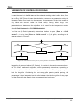
Figure 4. IRSC Zone Default topology
The following communication objects appear: "A/C Unit - ON/OFF Status", "A/C Unit Setpoint Status" and "A/C Unit - Fan Status", all of which will report basic information
about the states of the A/C unit (ON/OFF, setpoint and fan speed).
Seven more objects, of different lengths, are shown, referred to different functionalities
that may be controlled for Zone 1 (Zone 1 is the only zone enabled by default). These
are (“x” means 1 here):
Zone x – ON/OFF: permits turning ON or OFF each of the enabled zones
independently. Being ON implies a normal function of the zone, i.e., the
automatic control of its airing grille and the inclusion of its temperature setpoint
into the calculation process of the general temperature setpoint sent to the air
conditioning machine. On the other hand, when a zone is turned OFF, an order
to close the grille is sent to the bus, after which the setpoint of the zone is not
http://www.zennio.com
Technical Support: http://zennioenglish.zendesk.com
9
IRSC Zone
considered anymore (until the zone is turned on again) for the calculation of
the central setpoint.
Zone x – ON/OFF Status: indicates the current state (ON/OFF) of the
corresponding zone.
Zone x – Setpoint: permits receiving orders from the bus to change the
desired temperature setpoint (in ºC) for the corresponding zone.
Zone x – Setpoint Status: indicates the current value (in ºC) of the
temperature setpoint of the corresponding zone.
Zone x – Grille Control: sends orders (“0”=Close, “1”=Open) to the bus to
control the airing grille of the corresponding zone.
Zone x – Grille Status Reception: permits the arrival from the bus of
open/close orders for the airing grille of the corresponding zone, which –when
appropriate– makes the device respond with an updated order to the bus
through the “Zone x – Grille control” object.
Zone x – Reference Temperature: permits the reception from the bus of a
reference temperature, for example measured by a sensor installed inside the
corresponding zone.
If more zones are enabled (see section 3.2), the same seven objects will be available
for the remaining zones, with a different value for “x” in each case.
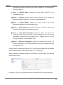
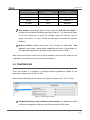
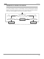
When entering the parameter edition of IRSC Zone for the first time, the following
window will be shown:
Figure 5. Configuration screen by default
As shown in Figure 5, the configuration screen is divided into the following main tabs:
http://www.zennio.com
Technical Support: http://zennioenglish.zendesk.com
10
IRSC Zone
General: general configuration of the basic functionalities of the air
conditioning system to be controlled.
Mode: mode selection type permitted by the A/C machine.
Fan: parameters related to the control of the fan speed of the A/C machine.
Temperature: parameters related to the temperature setpoint sent to the A/C
machine.
Thermostat: selection and configuration of the parameters related to the
thermostat, both for the Cool and the Heat modes.
Reset: selection of whether to send or not the different states of the A/C
machine to the KNX bus after a bus power failure or after an application or
parameter download.
All the aforementioned tabs are explained in detail in the next sections.
3.2 GENERAL
As shown in Figure 5, in the General window it is possible to configure the main
parameters of the A/C system being controlled. These are:
Model: sets the code number (between 0 and 255) associated to the remote
control to be emulated (please refer to the correspondence table at
http://www.zennio.com).
No. of Zones: selects how many zones are to be acclimatised (from 1 to 8).
Depending on the number established here, seven communication objects will
appear associated to each zone (those associated to Zone 1 are enabled by
default), making it possible to send and/or receive different orders related to
the acclimatization of the zone: On/Off, Setpoint, Grille control and reference
temperature (see section 3.1).
Shut Down A/C Unit if all Grilles are OFF: this parameter allows defining the
behaviour of the A/C machine when the grilles of all the enabled zones are
closed. If this parameter is enabled ("Yes"), when all the grilles are closed (i.e.,
http://www.zennio.com
Technical Support: http://zennioenglish.zendesk.com
11
IRSC Zone
all the "Zone x - Grille Control" objects have the value "0") the A/C machine
will be switched off. This option may be interesting for systems where a bypass
to avoid excessive overpressures is not available.
Delay to Turn ON A/C if any Grille is ON: field to set the time, in
seconds, the device will wait before switching on the A/C unit after a grille
is opened again ("Zone x - Grille Control" = 1). This option may be
interesting for systems with thermally-driven grilles.
Additional Bypass: the activation ("Yes") of this parameter allows controlling
a bypass or additional grille through which the exceeding air conditioned from
the installation could be canalised, thus preventing over-pressure.
Open Bypass if no. of Open Grilles Lower or Equal Than: defines the
maximum permitted number of closed grilles (from 0 to 8) before an order
to open the bypass is forced (via the "Additional Bypass" object). In other
words, the bypass will stay open while the number of open grilles is equal
or lower than the number set for this parameter. For instance, if the value
“4” is typed here, the bypass will stay open while the number of open
grilles is 4, 3, 2, 1 or 0 (in the case of 0, this will be true only if the machine
is ON). Note that no matter what the value of this parameter is, the bypass
will stay open if the A/C machine is ON and all the grilles are closed.
Zone Update on Start-up: permits activating or deactivating the sending of
certain read requests to the bus after a download or a device reset order from
ETS. These requests make it possible for IRSC Zone to assimilate the state of
the environment (setpoints, temperatures, modes) at the moment of beginning
to function. Read orders are therefore sent through the following objects, for
every enabled zone:
Zone x – ON/OFF
Zone x – Setpoint
Zone x – Reference Temperature
Read orders will also be sent through the following control objects, if enabled:
A / C Unit – Modes
http://www.zennio.com
Technical Support: http://zennioenglish.zendesk.com
12
IRSC Zone
A / C Unit – Simplified Mode
A / C Unit – Fan Precise
Temperature Restriction
It is important that the communication objects being requested are linked
(through the same group addresses) to those from any external device aware
of the state at any time, and that the Read flag (“R”) is enabled for them.
Otherwise IRSC Zone may not be able to receive feedback from them.
Consequently, instead of adopting the default values, IRSC-Zone will listen to
the responses received from the KNX environment, therefore making it
possible that IRSC-Zone recovers the control over a particular situation
(where, for instance, certain zone setpoints have already been set) no matter if
successive downloads or resets from ETS take place, and without the need of
acting again over the user interfaces (such as the InZennio Z41 touch panel)
that let the user set those values and therefore make IRSC-Zone aware of
them. It is recommended, however, to enable sending the statuses to the bus
on start-up (see section 3.7), so that the actual status of the grilles matches at
any time the one assumed or calculated by the controller, for example, after a
download.
Enabling this parameter also brings the following two:
Delay [x 1 sec]: sets a certain delay to be counted since the end of the
start-up process of the device, before the corresponding read requests are
sent to the bus.
Zone Update After Reset?: if this parameter is enabled, the already
mentioned read requests will also take place after power failures or after
disconnecting and connecting the device.
Note: if one or more particular objects do not get a response to their read
requests, they will maintain their default values. On the other hand, if IRSC
Zone does receive a response to the read request of the “ON/OFF”, “Setpoint”
and “Reference Temperature” objects before having the response to the read
request of the Mode object, the calculation of the general setpoint and the grille
control will take place by initially assuming the default mode (Cool). If
http://www.zennio.com
Technical Support: http://zennioenglish.zendesk.com
13
IRSC Zone
afterwards a response is received to the Mode request and it turns to be other
than Cool, this control will be restarted and, typically, the unit will be sent new
orders while the grille state also changes, if needed.
3.3 MODE
The Mode window allows configuring features related to the selection of the operating
mode of the A/C machine, which is made assuming that the A/C machine supports the
selection of up to five working modes:
Cool: intended for zone cooling. When IRSC Zone receives an order to
commute to this mode, it sends the corresponding mode switch order to the
unit, and begins to control the grilles of every zone according to how the
thermostat control for cooling has been parameterised, and to whether the
reference temperatures are higher or not than the setpoints (see section 3.6 as
well as Annex II. Grille control and Annex III. Practical example).
In relation to the calculation of the general setpoint, mode “Cold” implies, on
the one hand, switching from one range of accepted temperature setpoints to
another range of accepted temperature setpoints (see Section 3.5). And on the
other hand, the fact that the general temperature setpoint must be lower or
equal than the coolest of the zone temperature setpoints.
Heat: intended for zone heating. When IRSC Zone receives an order to
commute to this mode, it sends the corresponding mode switch order to the
unit, and begins to control the grilles of every zone according to how the
thermostat control for heating has been parameterised, and to whether the
reference temperatures are higher or not than the setpoints (see section 3.6 as
well as Annex II. Grille control and Annex III. Practical example).
In relation to the calculation of the general setpoint, mode “Heat” implies, on
the one hand, switching from one range of accepted temperature setpoints to
another range of accepted temperature setpoints (see section 3.5). And on the
other hand, the fact that the general temperature setpoint must be greater or
equal than the hottest of the zone temperature setpoints.
http://www.zennio.com
Technical Support: http://zennioenglish.zendesk.com
14
IRSC Zone
Auto: destined to let the machine decide by itself how to behave at each
moment (sending cold air / sending hot air).
Fan: destined to generate a simple air flow, typically at ambient temperature,
from the air conditioning machine. When this mode begins, IRSC Zone keeps
the air grilles of every enabled zone permanently open
Dry: destined to generate a dry air flow, typically at ambient temperature, from
the air conditioner machine, so that the humidity in the air is reduced.
As shown in Figure 6, the Mode window allows configuring the commutation from one
mode to another will be performed:
Figure 6. Mode window
Individual Control: when this option is selected, all the described working
modes will be selectable through one specific 1-bit communication: this means
that 5 objects will be deployed for establishing one of the available modes
(Auto, Cool, Fan, Heat and Dry), by sending the value "1" through them, as
well as 5 more objects for reflecting the status (active, not active) of every
individual mode.
1 Byte Control: when this option is selected, the working modes can be
controlled through a unique 1-byte communication object, "A/C Unit - Modes [1
byte]", by sending the value corresponding to the mode to be activated. It is
also possible to check at any time the current working mode of the A/C unit, via
the "A/C Unit - Mode Status [1 byte]" 1-byte object.
Simplified Control: when this option is selected, the "A/C Unit - Simplified
Mode" 1-bit object will be enabled. It allows establishing the desired mode:
Cool mode (writing the value "0" in the object), or Heat mode (writing the value
"1"). There is no status object associated to this control object.
The three control types can be enabled jointly, making it possible to control the
functioning mode by alternative means at any time. Note that, anyway, changing from
http://www.zennio.com
Technical Support: http://zennioenglish.zendesk.com
15
IRSC Zone
one mode to another has two major consequences: first, the sending of the mode
switch order to the machine; and second, switching IRSC Zone (when required) from
one thermostat and grille control type to another.
Note: the algorithm for controlling the zone airing grilles (open/close) is available in
Annex II. Grille control. In addition, section 3.5 and Annex III. Practical example explain
the calculation process of the general setpoint, based on the zone temperature
setpoints and the current working mode.
3.4 FAN
The Fan window allows selecting how the fan speed control of the A/C machine will be
performed
Figure 7. Fan window
Fan Restriction Based on the No. of Open Grilles: if this parameter is
enabled ("Yes"), it will be possible to limit the air flow from the A/C unit
according to the number of open grilles. The levels that may be set are: “Only
Medium”, “Only Minimum” or “Medium and Minimum”. Depending on the
selected option, one of the following boxes will be shown (or both, if “Medium
and Minimum” is selected).
Force Minimum Fan Under: sets the minimum number of grilles that must
be open before it is permitted to leave the minimum fan speed (object "A/C
Unit - Fan Status" will reflect the current fan speed; see Table 1).
Force Medium Fan Under: sets the minimum number of grilles that must
be open before it is permitted to commute from the medium fan speed to
the maximum fan speed (object "A/C Unit - Fan Status" will reflect the
current fan level; see Table 1).
http://www.zennio.com
Technical Support: http://zennioenglish.zendesk.com
16
IRSC Zone
Initial speed percentage
Interpolated speed
percentage
Level
0%
0%
Auto
1-33%
33%
Minimum
34-66%
66%
Medium
67-100%
100%
Maximum
Table 1. Fan speed percentages
Step Control: selecting this option ("Yes") brings the "A/C Unit - Fan Step" 1bit object, which allows increasing (sending the value "1") or decreasing (value
"0") the fan speed by one level (for example, under the minimum level of
speed, if the value "1" is sent via this fan step object, the speed will become
medium).
Precise Control: selecting this option ("Yes") brings the "A/C Unit - Fan
Precise" 1-byte object, which allows establishing the value, in percentage, of
the desired fan speed level, according to the values shown in Table 1.
Step control and Precise control can be jointly enabled, so that the fan speed can be
controlled in one manner or other at any time, as desired.
3.5 TEMPERATURE
From this window it is possible to configure several parameters related to the
temperature setpoint sent to the A/C Unit.
Note that the parameters shown below do not apply in modes “Auto”, “Fan” or “Dry”.
Figure 8. Temperature window
Temperature Range (only for Heat and Cool modes): it is possible to define
limits for the temperature setpoint sent to the machine of each mode:
http://www.zennio.com
Technical Support: http://zennioenglish.zendesk.com
17
IRSC Zone
Cool Mode Min. Temperature: establishes the minimum general
temperature setpoint, in ºC, allowed for the Cool mode. This value must be
in the range 16-30ºC.
Heat Mode Max. Temperature: establishes the maximum temperature
setpoint, in ºC, allowed for the Heat mode. This value must be in the range
16-30ºC.
Once this option has been enabled, the “Temperature Restriction” 1-bit
object becomes available, with value “1” by default. Temperatures will be
subject to the above limits only while the value of this object is "1". The value
“0”, on the other hand, means that the parameterised restriction should be
escaped.
If a setpoint over the maximum limit or under the minimum level is calculated
while the temperature restriction is active, the setpoint value effectively sent
to the A/C unit will become truncated to the corresponding limit.
Note: the temperature setpoint sent to the machine may exceed the
parameterised restrictions (even if the “Temperature Restriction” object has
the value “1”) in the case of having parameterised a calibration (parameter
“Increase (heat) / Decrease (cool) Temperature Sent to the A/C Unit by”,
explained below) or if the “Temperature Returned from External Sensor”
parameter, explained next, is enabled.
Note 2: some particular details apply in case of enabling the temperature
restriction together with the Calibration or the External return temperature
functions. For further details, please refer to Annex III. Practical example.
Temperature Returned from External Sensor: this parameter can be
optionally enabled, if a return air duct exists, with the aim of adapting the
general setpoint calculation process in certain cases when a heat or cool
source is affecting the temperature of the returned air that arrives back to the
http://www.zennio.com
Technical Support: http://zennioenglish.zendesk.com
18
IRSC Zone
machine, while it does not affect the ambient temperature of the enabled
zones.
Once this parameter is enabled, a 2-byte object, “External Temperature
Returned”, shows up so it can be linked to a KNX sensor (refer to Annex I.
Installation Scheme to better identify the proper location for the sensor in the
installation). During the calculation of the general setpoint, IRSC Zone will
consider this return temperature as an additional reference, so it will compare it
to the setpoints of the different zones that are ON at that moment. If the return
temperature is higher (mode “Heat”) or lower (mode “Cool”) than the desired
temperatures for the zones, IRSC Zone will require the machine to make an
“extra effort”, and will send (through the “A/C Unit – Setpoint Status” object) a
general setpoint equal to the return temperature increased (mode “Heat”) or
decreased (mode “Cool”) by 1ºC. It is recommended to read the application
example in Annex III. Practical example for a better comprehension.
Note: it is necessary that the external KNX sensor periodically sends the
measured temperature (the period should not be more than one hour). In case
IRSC Zone does not receive any temperature through the Returned
Temperature object within 60 minutes, it will stop taking into account this
external temperature for the calculation process.
Increase (heat) / Decrease (cool) temperature sent to the A/C unit by: sets
an additional temperature value (calibration), in ºC, which will be taken into
account while calculating the temperature setpoint that will be sent to the A/C
unit. Depending on the current working mode of the machine (Heat or Cool),
this value will be added or subtracted, respectively, to the resulting
temperature (after applying the restrictions and the comparison to the returned
temperature, if they apply).
To better understand all these concepts, an application example has been included in
Annex III. Practical example of this manual.
http://www.zennio.com
Technical Support: http://zennioenglish.zendesk.com
19
IRSC Zone
3.6 THERMOSTAT
From the Thermostat window it is possible to enable and configure the thermostat
functionality for cooling, heating or both.
In the case of not enabling a certain thermostatic control (the one for cooling, the one
for heating or both), the status of the grilles will be determined by the status of their
zone (zone ON, grille open; zone OFF, grille closed).
Figure 9. Thermostat window
Both, the Cool thermostat and the Heat thermostat, admit the following configurable
parameters:
Control Type: permits selecting one of these options: 2-point control or PI
control (PWM).
2-Point Control
•
Lower/Upper Hysteresis: the desired value, in tenths of a degree, for
the lower and upper hysteresis, respectively.
PI Control (PWM)
•
Cycle Time: value, in minutes, for the sending period of the PWM
control variable during the grille control process.
•
Proportional Band: parameter required for calculating the proportional
integral function, expressed in Kelvin.
•
Integral Time: parameter required for calculating the proportional
integral function, expressed in minutes.
http://www.zennio.com
Technical Support: http://zennioenglish.zendesk.com
20
IRSC Zone
Annex II. Grille control includes a brief introduction to these two thermostatic control
methods, and to what they involve in relation to grille control. In addition, to obtain
detailed information about all these parameters related to the thermostatic control,
please refer to the specific document "Zennio Home Thermostat", available at
http://www.zennio.com.
3.7 RESET
From this window, it is possible to configure whether to send or not to the KNX bus
and/or to the A/C unit the statuses of the different options that have been enabled by
parameter, after recovering from a bus power failure and/or after a device reset or a
download from ETS.
Figure 10. Reset window
Sending Statuses to Bus on Bus Voltage Recovery: it allows choosing
whether to send the status objects of the A/C unit to the KNX bus or not after a
bus power failure, a device reset order from ETS or a download.
Sending of Grille Statuses: sets if grille status objects ("Zone x - Grille
Status Reception") should be sent to the bus in addition to the machine
status objects after a bus power failure, a device reset from ETS or a
download.
Delay: time, in seconds, that IRSC will wait before proceeding with this
sending.
http://www.zennio.com
Technical Support: http://zennioenglish.zendesk.com
21
IRSC Zone
Sending Status to A/C Unit on Bus Voltage Recovery: allows choosing
whether to send or not the current status values to the A/C unit (i.e., through
infrared commands) after a bus power failure, a device reset from ETS or a
download.
Delay: time, in seconds, that IRSC will wait before proceeding with this
sending.
Related to device reboots, there is also the option to make IRSC Zone send read
requests to the bus in order to get updated values of the objects that determine the
initial state it should assume when it becomes functional. Such option (Zone update
on start-up) has been described in section 3.2.
Note: when the initial sending is enabled from the Reset window having already
enabled the “Zone Update on Start-up” parameter from General, special attention must
be paid while setting the delays of both parameters. The purpose of enabling the latter
is that IRSC Zone requests state information from the KNX system, so it would not
make sense that, prior to this, IRSC Zone had already sent control orders, thus
overwriting the original state.
http://www.zennio.com
Technical Support: http://zennioenglish.zendesk.com
22
IRSC Zone
ANNEX I. INSTALLATION DIAGRAM
Figure 11 shows a typical diagram of an installation with three different climate zones,
controlled by an IRSC Zone.
Figure 11. Scheme Installation example
The IRSC interface (programmed with the IRSC Zone application program) carries out
the thermostatic control of the installation by receiving data from an external touch
panel (InZennio Z38i or InZennio Z41) and from a sensor (QUAD), which measures the
temperatures of the different zones enabled in the installation. With this input data, and
according to the configuration parameterised in ETS, IRSC Zone will send orders, via
IR commands, to the central A/C machine to acclimatise the installation zone by zone,
as desired.
To get an optimal acclimatization, it is recommended to install the external sensor in
the inner side of the returning pipe, as closest as possible to the central A/C machine.
http://www.zennio.com
Technical Support: http://zennioenglish.zendesk.com
23
IRSC Zone
ANNEX II. GRILLE CONTROL
SWITCHING THE ZONES ON / OFF
Mode switch /
Reset of variables
Order to switch off / Grille gets closed
Zone
is ON
Setpoint Change /
Reset of variables
Zone is
OFF
Order to switch on / Reset of variables
Figure 12. "Zone ON" / "Zone OFF" state diagram
While the zone is in the ON state, the thermostatic control and the grille control stay
active, so the temperature setpoint of the zone is taken into account by the device in
order to calculate the general temperature setpoint for the air conditioning unit, after
which it will periodically send, when required, the pertinent Open or Close orders to the
zone grille depending on the particular setpoint and reference temperatures of that
zone 1.
During this process, every time the user changes the zone setpoint, as well as
whenever the working mode is changed, all the variables are reset and the calculation
is resumed according to the new mode and the new setpoint. If, on the contrary, a zone
switch-off order arrives, IRSC Zone will close the corresponding grille and will stop
considering the setpoint of that zone for the calculation of the A/C unit general setpoint.
While the zone is OFF, every mode change order and every setpoint change order will
be ignored. Only once the zone is switched on again, IRSC Zone will resume the
corresponding calculation and will send the order to open back the grille, if such order
is considered to be required.
1
As explained in section 3.6, if no thermostatic control has been enabled, the grilles will stay
open as long as the zone is ON, and closed as long as it is OFF.
http://www.zennio.com
Technical Support: http://zennioenglish.zendesk.com
24
IRSC Zone
THERMOSTATIC CONTROL FOR COOLING
In case the zone is in the ON state and the selected working mode is either Auto, Cool,
Fan or Dry, IRSC Zone will base the calculation process on the parameters set by the
integrator for the Cool mode (on the contrary, the parameters of the Heat mode are
only taken into account under the Heat mode). Among other things, such
parameterisation determines the algorithm to be used for the temperature control:
either 2-Point Hysteresis or PI (PWM Modulation).
The first one (2-Point Hysteresis) determines whether to open (“Zone x – Grille
control” = 1) or to close (“Zone x – Grille control” = 0) the grille, according to the
diagram shown in Figure 13.
Yes
(“it is hot”)
Grille is open?
No
(“it is cold”)
T REF > T SETPOINT + HUpper
Yes
Do nothing
Yes
No
Grille is closed?
No
Open grille
Close grille
Figure 13. Grille behaviour during the "2 point hysteresis" thermostatic control for cooling
Regarding the second method (PI Control), it consists in the continuous execution of
the “PI control” mathematic algorithm, which permanently determines, depending on
how the setpoint and the reference temperature of the zone differ, the proper opening
level for the grille. Considering that not every grille permits partial opening, this
percentage is then interpreted as the ratio between the time the grille will stay open
and the time it will stay closed, given the parameterised cycle time.
http://www.zennio.com
Technical Support: http://zennioenglish.zendesk.com
25
IRSC Zone
THERMOSTATIC CONTROL FOR HEATING
In an exactly analogous manner, the thermostatic control for heating permits selecting
between a 2-point with hysteresis control and a PI control with pulse width modulation.
In this case, the flow diagram for the first one is as shown in Figure 14.
Yes
(“it is cold”)
Grille is open?
No
Open grille
No
(“it is hot”)
T REF < T SETPOINT + HLower
Yes
Do nothing
Yes
Grille is closed?
No
Close grille
Figure 14. Grille behaviour during the 2 point with hysteresis" thermostatic control for heating
http://www.zennio.com
Technical Support: http://zennioenglish.zendesk.com
26
IRSC Zone
ANNEX III. PRACTICAL EXAMPLE
The following example is provided with the aim of making it easier to understand the
concepts explained in this manual and the parameterization process of the device.
Suppose a KNX installation as the one in the figure, where three zones (Z1, Z2 and Z3)
are being acclimatised in the “Heat” mode by an IRSC Zone and an A/C unit. Also
assume that zone Z3 has been switched off and that a maximum temperature of 24ºC
has been parameterised for the Heat mode, and that the “Temperature Restriction”
object has been previously assigned the value “1”.
IRSC-Zone
QUAD
ACTinBOX
Classic-Hybrid
Temp.
Probe
A/C
Heat Source
Z1. TCONS = 24
M
Z2. TCONS = 25
Z3. TCONS = 23
M
M
Under these circumstances, if the “External Temperature Returned” parameter is found
to be disabled, IRSC Zone analyses the temperature setpoints of zones Z1 and Z2
(since Z3 has been switched off):
The general setpoint will be, at first, the maximum among them: 25ºC.
Because of the temperature restriction, this will be truncated to 24ºC.
If, furthermore, an additional calibration of +1ºC has been parameterised for
http://www.zennio.com
Technical Support: http://zennioenglish.zendesk.com
27
IRSC Zone
“Increase/decrease Temperature Sent to the A/C unit”, an extra degree will be
added, resulting a final setpoint of 25ºC (note that the calibration has a higher
priority than the parameterised temperature range).
However, since there is a heat source that overheats the air returning to the machine,
the built-in thermostatic control of the A/C unit understands that the ambient
temperature is high enough (even higher than the setpoint), which makes the unit stop
generating heat, even if the ambient temperatures in Z1 and Z2 is different from that
measured by the internal sensor of the A/C unit. To prevent this situation, it is
convenient to enable the “Temperature Returned from External Sensor” parameter in
ETS, as the temperature measured in the return air duct is approximately equal to that
registered by the internal sensor of the A/C unit. For instance:
External temperature returned = 26.5ºC
IRSC Zone will then look for the maximum among the temperature setpoints of zones
Z1 and Z2, and, afterwards, for the maximum between this (25ºC, which is truncated to
24ºC) and the external temperature (26.5ºC), resulting to be 26.5ºC. By default, this
value is then internally increased by one degree (27.5ºC) when the external
temperature function is active. And then, another degree is added again because of the
parameterised calibration (28.5ºC). Finally, the value 28.5ºC is sent to the unit through
the “A/C Unit – Setpoint Status” object. This way, the air machine will keep
generating enough hot air even if its own sensor is measuring an ambient temperature
of about 26.5ºC. To sum up:
Setpoint comparison 26.5ºC.
Restriction 24ºC.
External return temperature 26.5ºC.
Extra degree (because of the external return temperature) 27.5ºC
Calibration 28.5ºC. (value sent to the machine).
From that moment, IRSC Zone will send the appropriate orders to the grilles in zones
Z1 and Z2 (according to the parameterised algorithm for the thermostatic control for
heating) so that the heat generated by the unit is conveniently directed to the zones,
depending on their setpoint and reference temperatures.
http://www.zennio.com
Technical Support: http://zennioenglish.zendesk.com
28
IRSC Zone
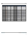
ANNEX IV. COMMUNICATION OBJECTS
“Functional range” shows the values that, with independence of any other values permitted by the bus according to the object size, may be of any use or have a particular
meaning because of the specifications or restrictions from both the KNX standard or the application program itself.
“1st boot” shows the cases where an object is assigned a certain value by the application program after a device download or a full reset. In case the value of such
assignment can be parameterised, √ is shown in column “P”. Objects showing a hyphen (-) are not assigned a particular value and therefore can be assumed to be
initialised with the value “0” or with the corresponding updated value in case they depend on an external element (sensors, etc.). Moreover, if the object is sent (or is there
an option to send it) to the bus (write or read requests) after a download or a device reset from ETS, the marks (W) or (R) will be shown, respectively for transmissions or
read requests.
“Reboot” shows the cases where an object is assigned a certain value by the application program after a bus power failure. In case the value of such assignment can be
parameterised, √ is shown in column “P”. Objects showing a hyphen (-) are not assigned a particular value and therefore can be assumed to maintain their previous value
after the failure or with the corresponding updated value in case they depend on external elements (sensors, etc.). Moreover, if the object is sent (or is there an option to
send it) to the bus (write or read requests) after a bus failure, the marks (W) or (R) will be shown, respectively for transmissions or read requests.
Number
Size
I/O
Flags
Data Type (DPT)
Functional Range
1st boot
0
1 Bit
O
CTR--
DPT_Switch
0/1
- (W)
P
Reboot
- (W)
P
A/C Unit - ON/OFF Status
Name
0=Off; 1=On
Function
1
2 Bytes
O
CTR--
DPT_Value_Temp
-273.00 – 670760.00
25.00 (W)
- (W)
A/C Unit - Setpoint Status
Temperature setpoint sent
0%Au;1-33%Mi;34-66%Med;>67%Max
2
1 Byte
O
CTR--
DPT_Scaling
0% - 100%
25% (W)
- (W)
A/C Unit - Fan Status
3 - 10
1 Bit
I
CT-WU
DPT_Switch
0/1
- (R)
- (R)
Zone x - ON/OFF
0=Off; 1=On
11 - 18
1 Bit
O
CTR--
DPT_Switch
0/1
-
-
Zone x - ON/OFF Status
0=Off; 1=On
19 – 26
2 Bytes
I
CT-WU
DPT_Value_Temp
-273.00 – 670760.00
25.00 (R)
- (R)
Zone x - Setpoint
Temperature setpoint
27 - 34
2 Bytes
O
CTR--
DPT_Value_Temp
-273.00 – 670760.00
25.00
-
35 - 42
1 Bit
O
CTR--
DPT_Switch
0/1
- (W)
- (W)
43 - 50
1 Bit
I
C--WU
DPT_Switch
0/1
-
51 - 58
2 Bytes
I
CT-WU
DPT_Value_Temp
-273.00 – 670760.00
59
1 Bit
I
CT-W-
DPT_Switch
0/1
http://www.zennio.com
Zone x - Setpoint Status
Temperature setpoint
Zone x - Grille Control
0=Close; 1=Open
-
Zone 1 - Grille Status Reception
Link with Grille Status
- (R)
- (R)
Zone x - Reference Temperature
External Sensor Temperature
-
-
Additional bypass
0=Close; 1=Open
Technical Support: http://zennioenglish.zendesk.com
29
IRSC Zone
Number
Size
I/O
Flags
Data Type (DPT)
60
1 Byte
I
CT-WU
[20.105] DPT_HVACContrMode
61
1 Byte
O
CTR--
[20.105] DPT_HVACContrMode
62
1 Bit
I
CT-WU
[1.17] DPT_Trigger
63
1 Bit
O
CTR--
[1.17] DPT_Trigger
64
1 Bit
I
CT-WU
65
1 Bit
O
66
1 Bit
I
67
1 Bit
O
68
1 Bit
69
1 Bit
70
1 Bit
71
Functional Range
0=Auto; 1=Heat;
3=Cool; 9=Fan;
14=Dry
0=Auto; 1=Heat;
3=Cool; 9=Fan;
14=Dry
1st boot
P
Reboot
P
Name
Function
3 (R)
- (R)
A/C Unit - Modes [1byte]
0=Aut;1=Ht;3=Cool;9=Fan;14=Dry
3 (W)
- (W)
A/C Unit - Modes Status [1byte]
Actual Mode:0=Auto,1=Heat,etc.
0/1
-
-
A/C Unit - Heat Mode
1=Set Heat mode; 0=Nothing
0/1
-
-
A/C Unit - Heat Mode Status
1=Heat mode is Set; 0=Not Set
[1.17] DPT_Trigger
0/1
1
-
A/C Unit - Cool Mode
1=Set Cool mode; 0=Nothing
CTR--
[1.17] DPT_Trigger
0/1
-
-
A/C Unit - Cool Mode Status
1=Cool mode is Set; 0=Not Set
CT-WU
[1.17] DPT_Trigger
0/1
-
-
A/C Unit - Dry Mode
1=Set Dry mode; 0=Nothing
CTR--
[1.17] DPT_Trigger
0/1
-
-
A/C Unit - Dry Mode Status
1=Dry mode is Set; 0=Not Set
I
CT-WU
[1.17] DPT_Trigger
0/1
-
-
A/C Unit - Fan Mode
1=Set Fan mode; 0=Nothing
O
CTR--
[1.17] DPT_Trigger
0/1
-
-
A/C Unit - Fan Mode Status
1=Fan mode is Set; 0=Not Set
I
CT-WU
[1.17] DPT_Trigger
0/1
-
-
A/C Unit - Auto Mode
1=Set Auto mode; 0=Nothing
1 Bit
O
CTR--
[1.17] DPT_Trigger
0/1
-
-
A/C Unit - Auto Mode Status
1=Auto mode is Set; 0=Not Set
72
1 Bit
I
CT-WU
[1.100] DPT_Heat_Cool
0/1
3 (R)
- (R)
A/C Unit - Simplified Mode
0=Cool; 1=Heat
73
1 Byte
I
CT-WU
DPT_Scaling
0% - 100%
25% (R)
- (R)
A/C Unit - Fan Precise
0%Au;1-33%Mi;34-66%Me;>67%Max
74
1 Bit
I
C--WU
DPT_Switch
0/1
-
-
A/C Unit - Fan Step
0=Lower; 1=Higher
75
1 Bit
I
CT-WU
DPT_Enable
0/1
1
-
Temperature Restriction
1=T.Restricted; 0=No restric.
76
2 Bytes
I/O
CTRWU
DPT_Value_Temp
-273.00 – 670760.00
25.00
-
External Temperature Returned
External Sensor Temperature
http://www.zennio.com
Technical Support: http://zennioenglish.zendesk.com
30
Join and send us your inquiries
about Zennio devices:
http://zennioenglish.zendesk.com
Zennio Avance y Tecnología S.L.
C/ Río Jarama, 132. Nave P-8.11
45007 Toledo (Spain).
Tel. +34 925 232 002.
Fax. +34 925 337 310.
www.zennio.com
[email protected]