1
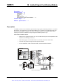
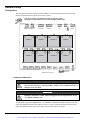
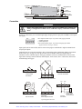
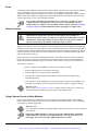
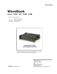
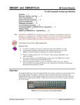
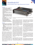
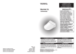
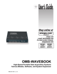
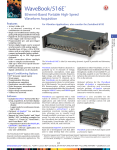
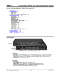
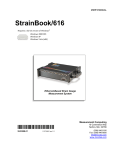
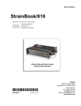
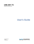
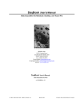
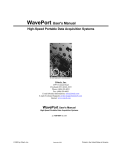
Artisan Technology Group is your source for quality
new and certified-used/pre-owned equipment
• FAST SHIPPING AND
DELIVERY
• TENS OF THOUSANDS OF
IN-STOCK ITEMS
• EQUIPMENT DEMOS
• HUNDREDS OF
MANUFACTURERS
SUPPORTED
• LEASING/MONTHLY
RENTALS
• ITAR CERTIFIED
SECURE ASSET SOLUTIONS
SERVICE CENTER REPAIRS
Experienced engineers and technicians on staff
at our full-service, in-house repair center
WE BUY USED EQUIPMENT
Sell your excess, underutilized, and idle used equipment
We also offer credit for buy-backs and trade-ins
www.artisantg.com/WeBuyEquipment
InstraView REMOTE INSPECTION
LOOKING FOR MORE INFORMATION?
Visit us on the web at www.artisantg.com for more
information on price quotations, drivers, technical
specifications, manuals, and documentation
SM
Remotely inspect equipment before purchasing with
our interactive website at www.instraview.com
Contact us: (888) 88-SOURCE | [email protected] | www.artisantg.com
WBK15
5B Isolated Signal-Conditioning Module
Description …… 1
Hardware Setup …… 2
Configuration …… 2
Connection …… 3
Power …… 4
Safety Concerns …… 4
Using Fastener Panels to Stack Modules …… 4
Software Setup …… 5
WBK15 – Specifications …… 7
Description
The WBK15 module can accommodate eight 5B isolated-input signal-conditioning modules for use with the
WaveBook. The WaveBook can accommodate 8 WBK15s for a maximum of 64 expansion channels. The
WaveBook scans WBK15’s channels at the same 1 µs/channel rate that it scans all WBK analog inputs,
allowing it to measure all channels of a fully configured 72-channel system in 72 µs.
Other features of WBK15 include:
• Built-in power supply that operates from 10 to 30 VDC and can power a full complement of 5B
modules (even with bridge excitation).
• Removable, plug-in screw-terminal blocks for convenient connection of 5B modules.
• On-board cold-junction sensing for thermocouple 5B modules.
• For each 5B module, 1500 V isolation from the system and from other channels.
Current-Sense
Resistor
Input
Terminal
Block
Channel 1
Cold
Junction
Sensor
Internal Jumpers
Buffered
LowPass
Filter
5B
Module
Socket
#1
5.000 V
Reference
CH1
CH2
CH3
CH4
CH5
CH6
CH7
CH8
Channel
Selection
MUX
+15 V
N
N
Analog
Output to
WaveBook
Control
DAC
Isolated
+5, ±15 VDC
Power
Power Supply
Switch
+V
Output
MUX
-15 V
Filters +5 V
DC Power
Input &
Expansion
BNC
Buffer
Amp
Channels 2-8 identical
GND
Bipolar
Offset
Amp
µP &
Control Logic
EEPROM
DIN-5
Expansion
Control
From
WaveBook
Status
LEDs
WBK15 Block Diagram
WBK15, 5B Isolated Signal Conditioning Module
988396
Artisan Technology Group - Quality Instrumentation ... Guaranteed | (888) 88-SOURCE | www.artisantg.com
WBK15, pg. 1
Hardware Setup
Configuration
The next figure shows the board layout within a WBK15. Note the channel-number layout for the 5B
modules and the location for plug-in current-sense resistors.
Only current-input type modules require the plug-in resistors.
The plug-in resistors must be removed for all other module types.
Rear Panel
BNC
DB15
DB15
DIN5
DIN5
Expansion
Control Out
Expansion
Control In
Power
Out
Power
In
BNC
Expansion Expansion
Signal Out Signal In
ON/OFF
Switch
Fuse
CHANNEL 1
ch 2
R10
R5
CHANNEL 2
ch 1
ch 2
CHANNEL 3
ch 4
ch 1
R16
R13
CHANNEL 5
ch 6
ch 3
R20
CHANNEL 4
ch 3
ch 4
R18
CHANNEL 7
ch 8
ch 5
CHANNEL 6
ch 5
Front Panel - signal inputs from 8 channels
WBK15 Board Layout
ch 6
R22
R23
ch 7
CHANNEL 8
ch 7
ch 8
Screw-terminal
Signal Plug
Status
LEDs
Installation of 5B Modules
WARNING
Electric shock hazard! Turn off power to WBK15 and all connected modules and
devices before inserting or removing modules. Failure to do so could lead to injury or
death due to electric shock.
CAUTION
Handle the 5B module carefully while inserting pins into the daughterboard. Do not
over-tighten mounting screw.
The 5B modules plug into a daughterboard (×2) on WBK15’s motherboard. Rubber bumpers on one side
and a tilted daughterboard allow the module to rest at a 5° angle to facilitate insertion and removal. The
adjacent daughterboard has a cut-a-way to allow room for a screwdriver (see figure).
WBK15, pg. 2
988396
WBK15, 5B Isolated Signal Conditioning Module
Artisan Technology Group - Quality Instrumentation ... Guaranteed | (888) 88-SOURCE | www.artisantg.com
5B Pins
(×14)
Screwdriver
5B Module
Daughterboard
Screw
Receptacle
5B Module
Pin (×14)
Receptacles
5°angle to
facilitate installation
WBK15 Main Board
Rubber Rest
Connection
5B Module Insertion/Removal
Mounting Screw
WARNING
Electric shock hazard! De-energize circuits connected to WBK15 before changing the
wiring or configuration. Failure to do so could lead to injury or death due to electric
shock.
Signals are connected by screw-terminal signal plugs that plug into the 4-pin jacks on WBK15’s front panel
(see figure).
-EXC -
+ +EXC
-EXC Negative excitation output - only used on strain-gage type modules
- Negative signal input
+ Positive signal input
+EXC Positive excitation output - only used on strain-gage type modules
Signal Connection Jacks (per channel)
Input signals (and excitation leads) must be wired to the plug-in terminal blocks. Eight 4-terminal blocks
accept up to 8 inputs.
Terminal blocks are connected internally to their corresponding signal conditioning module. The terminal
blocks accept up to 14-gage wire into quick-connect screw terminals. Each type of input signal or
transducer (such as a thermocouple or strain gage) should be wired to its terminal block as shown in the
figure below. Wiring is shown for RTDs, thermocouples, 20mA circuits, mV/V connections, and for fulland half-bridge strain gages.
SIG L SIG H
-EXC -Vin
+Vin +EXC
-EXC
+
Thermocouple
Connection
_
-Vin
+Vin +EXC
mV and V Connection
-EXC -Vin +Vin +EXC
Full-Bridge Strain-Gage Connection
-Vin
+Vin
4-Wire
+EXC
-EXC
-EXC -Vin
AC1362
2-Wire
3-Wire
+Vin +EXC
RTD Connection
-EXC -Vin +Vin +EXC
Half-Bridge
Strain-Gage Connection
4-20 mA
Connection
20 Ohm
Plug-In Resistor
(SC-AC-1362)
On-Board Socket
Typical Signal Connections
WBK15, 5B Isolated Signal Conditioning Module
988396
Artisan Technology Group - Quality Instrumentation ... Guaranteed | (888) 88-SOURCE | www.artisantg.com
WBK15, pg. 3
Power
Like the WaveBook, WBK15 contains an internal power supply. The unit can be powered by the included
AC power adapter or any 10 to 30 VDC source, such as a 12 V car battery. For portable or field
applications, WBK15 and the WaveBook can be powered by the DBK30A rechargeable battery module or
DBK34 vehicle UPS module. The supply input is fully isolated from the measurement system. If the fuse
requires replacement, it is a 2 A fuse (Littelfuse #251002).
Prior to daisy-chaining from one module’s power connector to another, be sure to
compute the power consumption for the entire system. Some modules may need
independent power adapters. The WaveBook manual’s chapter entitled, System Setup
and Power Options contains detailed information regarding power supply issues.
Safety Concerns
WARNING
Shock Hazard! Voltages above 50 Vrms AC and voltages above 100 VDC are
considered hazardous. Safety precautions are required when 5B modules are used in
situations that require high-voltage isolation from the rest of the system. Failure to
practice electrical safety precautions could lead to injury or death.
WBK15 is specified for 1500 VDC isolation in a normal environment free from conductive pollutants and
condensation. The 1500 VDC rating requires a proper earth ground connection to the chassis and treatment
of adjacent inputs as potentially hazardous. CE-marked units used in the European community are rated at
600 VDC isolation. The 600 VDC CE isolation specification is based on a double insulation requirement,
and no earth ground is required.
Input cables must be rated for the isolation potential in use. Line voltage ratings are much lower than the
DC isolation values specified due to transients that occur on power lines. Never open the lid unless all
inputs with potentially hazardous voltages are removed. The lid must be securely screwed on during use.
Some things to remember:
• Before closing up an open WBK15, ensure no foreign objects are inside.
• Properly tighten all chassis screws before system use.
• Properly tighten the screw that retains the 5B module.
• Never plug in or unplug potentially hazardous connections with power applied to any
connected equipment.
• Never attempt to change 5B modules or open the lid with power applied to the WBK15. You
could short out internally exposed circuits and cause personal injury or equipment damage.
Reference Note:
Refer to the System Setup and Power Options chapter of the WaveBook User’s Manual for
detailed information regarding the power aspects of WaveBook systems.
Using Fastener Panels to Stack Modules
For convenient mounting, the WBK15 has the same footprint as other WBK modules and WaveBooks.
Fastener panels (splice plates) provide a means for stacking WaveBooks and modules. Screw-on handles
are available for portable applications.
Reference Note:
For an illustration pertaining to mounting modules with fastener panels refer to the introduction
of this manual.
When using WBK17 modules in conjunction with other WBK modules, the WBK17
modules must be located closest to the WaveBook/516 (or /516A), due to the CA-217
cable length. The order of the other WBK modules does not matter.
WBK15, pg. 4
988396
WBK15, 5B Isolated Signal Conditioning Module
Artisan Technology Group - Quality Instrumentation ... Guaranteed | (888) 88-SOURCE | www.artisantg.com
Fastener panels will partially block the vents on WBK16, WaveBook/516, and
WaveBook/516A when stacked. This partial blocking of vents does not jeopardize the
cooling process.
Software Setup
You will need to set several parameters so WaveView can best meet your application requirements.
For detailed WaveView information, refer to the WaveView Document Module.
After the 5B module type is identified, WaveView figures out the m and b (of the mx+b equation) for
proper engineering units scaling. An example of the mx + b equation follows shortly.
Reference Note:
➣ For detailed WaveView information, refer to the WaveView Document Module.
➣ The API does not contain functions specific to WBK15. Refer to related material in the
Programmer’s Manual (p/n 1008-0901) as needed.
PDF Note:
During software installation, Adobe® PDF versions of user manuals automatically install onto
your hard drive as a part of product support. The default location is in the Programs group,
which can be accessed from the Windows Desktop. Refer to the PDF documentation for details
regarding both hardware and software. Note that you can also access PDF documents directly
from the data acquisition CD via the <View PDFs> button on the CD’s opening screen.
WaveView Configuration Main Window
mX +b, an Example
The Customize Engineering Units dialog box can be
accessed via the WaveView Configuration main
window by activating the Units cell [for the desired
channel], then clicking to select mX+b.
From the Customize Engineering Units dialog box
(see figure at right), you can enter values for m and b
components of the equation that will be applied to
the data. There is also an entry field that allows you
to enter a label for the new units that may result from
the mX+b calculation.
An example of mX + b equation use follows.
WBK15, 5B Isolated Signal Conditioning Module
988396
Artisan Technology Group - Quality Instrumentation ... Guaranteed | (888) 88-SOURCE | www.artisantg.com
WBK15, pg. 5
Engineering Units Conversion Using mx + b
Most of our data acquisition products allow the user to convert a raw signal input (for example, one that is
in volts) to a value that is in engineering units (for example, pressure in psi). The products accomplish this
by allowing the user to enter scale and offset numbers for each input channel, using the software associated
with the product. Then the software uses these numbers to convert the raw signals into engineering units
using the following “mx + b” equation:
Engineering Units = m(Raw Signal) + b (1)
The user must, however, determine the proper values of scale (m) and offset (b) for the application in
question. To do the calculation, the user needs to identify two known values: (1) the raw signal values, and
(2) the engineering units that correspond to the raw signal values. After this, the scale and offset parameters
can be calculated by solving two equations for the two unknowns. This method is made clear by the
following example.
Example
An engineer has a pressure transducer that produces a voltage output of 10.5 volts when the measured
pressure is 3200 psi. The same transducer produces an output of 0.5 volt when the pressure is 0 psi.
Knowing these facts, m and b are calculated as follows.
A - Write a pair of equations, representing the two known points:
3200 = m(10.5) + b (2)
0 = m(0.5) + b (3)
B - Solve for m by first subtracting each element in equation (3) from equation (2):
3200 - 0 = m(10.5 – 0.5) + (b - b) (4)
Simplifying gives you:
This means: m
3200 = m(10) (5)
= 320 (6)
C - Substitute the value for m into equation (3) to determine the value for b:
0 = 320 (0.5) + b (7)
So:
b = - 160 (8)
Now it is possible to rewrite the general equation (1) using the specific values for m and b that we just
determined:
Engineering Units = 320(Raw Signal) - 160 (9)
The user can then enter the values of m and b into the appropriate location using the facilities provided by
compatible data acquisition software, for example: WaveView, DaqView, Personal DaqView, LogView,
and TempView. The software uses equation (9) to calculate signal values in engineering units from that
point on.
WBK15, pg. 6
988396
WBK15, 5B Isolated Signal Conditioning Module
Artisan Technology Group - Quality Instrumentation ... Guaranteed | (888) 88-SOURCE | www.artisantg.com
WBK15 – Specifications
Name/Function: WBK15 Multi-Purpose Isolated Signal Conditioning Module
Connectors: 2 BNC connectors, mate with expansion signal input on the WaveBook/512, /512A, /516,
/516A, /516E; two 15-pin connectors, mate with the WaveBook’s Expansion Signal Control
Module Capacity: Eight 5B modules (optional) See latest catalog or contact your sales representative in
regard to the types of 5B Modules available for your application.
Input Connections: Removable 4-terminal plugs (Weidmuller type BL4, PN 12593.6,
or type BLTOP4, PN 13360.6)
Power Requirements: 10 to 30 VDC, or 120 VAC with included adapter
With 8 thermocouple-type modules: 12 VDC @ 0.25 A, 15 VDC @ 0.20 A, 18 VDC @ 0.2 A
With 8 strain-gage-type modules: 12 VDC @ 0.95 A, 15 VDC @ 0.75 A, 18 VDC @ 0.65 A
Cold-Junction Sensor: Standard per channel
Shunt-Resistor Socket: One per channel for current loop inputs
Isolation
Signal Inputs to System: 1500 VDC (600 VDC for CE compliance)
Input Channel-to-Channel: 1500 VDC (600 VDC for CE compliance)
Power Supply to System: 50 VDC
Dimensions: 221 mm × 285 mm × 36 mm (8.5” × 11” × 1.375”)
Weight: 1.8 kg (4 lb) [with no modules installed]
WBK15, 5B Isolated Signal Conditioning Module
988396
Artisan Technology Group - Quality Instrumentation ... Guaranteed | (888) 88-SOURCE | www.artisantg.com
WBK15, pg. 7
WBK15, pg. 8
988396
WBK15, 5B Isolated Signal Conditioning Module
Artisan Technology Group - Quality Instrumentation ... Guaranteed | (888) 88-SOURCE | www.artisantg.com
Artisan Technology Group is your source for quality
new and certified-used/pre-owned equipment
• FAST SHIPPING AND
DELIVERY
• TENS OF THOUSANDS OF
IN-STOCK ITEMS
• EQUIPMENT DEMOS
• HUNDREDS OF
MANUFACTURERS
SUPPORTED
• LEASING/MONTHLY
RENTALS
• ITAR CERTIFIED
SECURE ASSET SOLUTIONS
SERVICE CENTER REPAIRS
Experienced engineers and technicians on staff
at our full-service, in-house repair center
WE BUY USED EQUIPMENT
Sell your excess, underutilized, and idle used equipment
We also offer credit for buy-backs and trade-ins
www.artisantg.com/WeBuyEquipment
InstraView REMOTE INSPECTION
LOOKING FOR MORE INFORMATION?
Visit us on the web at www.artisantg.com for more
information on price quotations, drivers, technical
specifications, manuals, and documentation
SM
Remotely inspect equipment before purchasing with
our interactive website at www.instraview.com
Contact us: (888) 88-SOURCE | [email protected] | www.artisantg.com