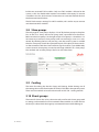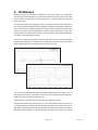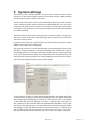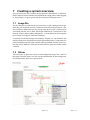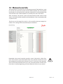
1
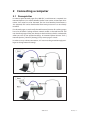
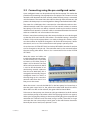
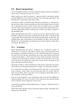
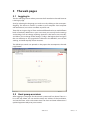
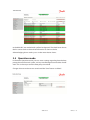
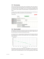
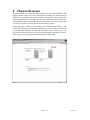
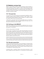
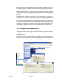
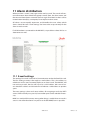
user’s manual
Web interface
DHP-R
4664-058-01
2 – Danfoss
4664-058-01
Contents
1Introduction�������������������������������������������������������� 5
2Connecting a computer�������������������������������������� 7
7.2 Values�������������������������������������������������������������������� 23
7.3 Hints���������������������������������������������������������������������� 24
2.1 Prerequisites����������������������������������������������������������� 7
8Internet connection������������������������������������������ 25
2.2Connecting using the pre-configured router������� 8
8.1Internet connection using the
pre-configured router������������������������������������������ 25
2.3 Direct connection��������������������������������������������������� 9
2.3.1 IP number�������������������������������������������������������������������������������������������������9
8.2Connection to an existing network��������������������� 25
8.2.1 DHCP��������������������������������������������������������������������������������������������������������25
3The web pages�������������������������������������������������� 11
3.1Logging in������������������������������������������������������������� 11
3.2
Heat pump overview������������������������������������������� 11
8.2.2 Fixed IP number�����������������������������������������������������������������������������������26
8.2.3 Gateway and DNS��������������������������������������������������������������������������������26
8.2.4 Port redirect�������������������������������������������������������������������������������������������26
8.3New internet connection������������������������������������� 27
3.3Alarms������������������������������������������������������������������� 12
8.3.1 The router�����������������������������������������������������������������������������������������������27
3.4 Operation mode��������������������������������������������������� 13
8.3.2 Port forward and NAT�������������������������������������������������������������������������27
3.5 Heat pump������������������������������������������������������������ 14
9The portal server���������������������������������������������� 29
3.6 Heat control���������������������������������������������������������� 14
3.7Tap water control������������������������������������������������� 15
10 Modem connection������������������������������������������ 31
3.8Slave pumps���������������������������������������������������������� 16
10.1 Prerequisites��������������������������������������������������������� 31
3.9Cooling������������������������������������������������������������������ 16
10.2Settings in the WM HPC��������������������������������������� 31
3.10 Shunt groups������������������������������������������������������� 16
10.3Remote connection���������������������������������������������� 31
10.4Example from Windows XP���������������������������������� 32
4 Databases���������������������������������������������������������� 17
11Alarm distribution�������������������������������������������� 33
5Service log��������������������������������������������������������� 19
6System settings������������������������������������������������� 21
7Creating a system overview����������������������������� 23
7.1Image file�������������������������������������������������������������� 23
11.1E-mail settings������������������������������������������������������ 33
11.2Alarm distribution settings��������������������������������� 34
11.3SMS settings��������������������������������������������������������� 34
12 Manual override����������������������������������������������� 35
4664-058-01
Danfoss – 3
4 – Danfoss
4664-058-01
1Introduction
The WM HPC control system has a web based user interface. This enables an
ordinary web browser to be used for a graphical user interface, and enables
access from distant locations. Everything that can be done using the operator
panel can also be done through the web interface. Additional features, such as
a system overview, databases, and alarm distribution through e-mail or SMS,
are exclusive to the web interface.
This manual should be seen as a complement to the user manual for the control
system. Since the settings are the same as in the operator panel, their function
and meaning will not be explained again. Instead, chapter three is devoted to
explaining how to find and use things in the web user interface.
To access the web pages, a computer has to be connected to the WM HPC unit.
Chapter two describes how to do this using the pre-configured router that is
sold as an accessory. It also describes how to make a direct connection, if the
router is not available. Chapter eight describes how to connect the heat pump
to a local network or to the Internet, and chapter nine discusses how to connect using a modem.
4664-058-01
Danfoss – 5
6 – Danfoss
4664-058-01
2Connecting a computer
2.1 Prerequisites
In order to open the web pages for a WM HPC, a web browser is required. Use
Internet Explorer 5.5 or newer, Mozilla Firefox 2.0 or newer, or Netscape 9.0 or
newer. Java script has to be activated. The Sun Java Runtime Environment is
also required, and can be downloaded from www.java.com if it is not already
installed.
For the web pages to work well, the web browser function for caching pages
has to be disabled. Caching reduces network traffic as the web browser will
not download pages if they are already on the hard drive, which is undesirable
when you wish to see updated readings. In Internet Explorer choose: Tools |
Internet Options | General | Settings | Every time a page is visited.
In order to set up a direct connection, a PC user must be granted enough privileges to change network settings.
4664-058-01
Danfoss – 7
2.2Connecting using the pre-configured router
A pre-configured router can be purchased with the heat pump. This makes the
procedure of connecting a heat pump easier. The purpose of a router is to route
network traffic between the local network where the heat pump is connected
and the Internet. The router limits the traffic let through from the Internet, and
protects the heat pumps to some degree from being overwhelmed with traffic.
The router has a WAN port that is connected to a broadband modem or broadband network outlet. The router also has four network outlets to connect
heat pumps. If four does not suffice, a network switch may be used to connect
additional local networks. A network cable is connected between the network
outlet on a WM HPC and a free outlet on the router.
If there is more than one heat pump, their network addresses must be changed
so that they all do not have the same address. The default setting is 10.0.48.94.
If there is only one heat pump there is no need to change this address, otherwise the number 94 should be changed to 101 for the first heat pump, 102 for
the second, and so on. This can be done on each pump’s operator panel.
Go to the menu SYSTEM SETTINGS and select NETWORK. Here the IP number
can be changed to 10.0.48.101. The controller needs to be restarted before
the new setting takes effect. There is also a command for this under SYSTEM
SETTINGS.
When the router and cables are
installed and the network addresses are correctly set, it is possible
to browse to the heat pumps if
there is a PC on location. On most
office and home networks, DHCP
is used to lift the burden of administrating network addresses
from the user. With DHCP this is
managed automatically. The preconfigured router has DHCP, so
the only thing to do is connect a
network cable from the PC to a
free port on the router.
When the router is on and the WM HPC in the heat pump has booted up so
that the green status led is lit, the yellow led marked LINK should also be lit.
When there is traffic on the network, the green LAN led should blink.
To browse to a heat pump start a browser and type 10.0.48.94 (or the IP number
set in the heat pump) in the address field. The login page should soon appear.
Select your language by clicking on the corresponding flag. Your computer will
remember this selection until next time (using a cookie). Then click on Login
and enter the user name and password given on the web licence document.
Normally the access level (user) operator is used.
8 – Danfoss
4664-058-01
2.3 Direct connection
If a pre-configured router is not used, read this chapter instead. It will explain
how to access a heat pump from a PC on site.
When setting up a direct connection, a network cable is connected directly
from the WM HPC to a PC. A direct connection is also possible when the PC and
the WM HPC is connected to the same switch.
The network cable, an Ethernet cable with RJ45 connectors, is connected to
the network socket on the top right hand side of the WM HPC unit. The other
end is connected to the PC or to a switch. If it is connected to a PC, a so-called
crossed cable may be required, but newer computers often handle both crossed and straight cables. When connecting to a switch, an ordinary straight cable should be used.
If both the WM HPC and the PC or switch are on, the yellow Link-led on the
WM HPC should be lit. The green LAN led blinks when there is network traffic
on the cable. If the Link-led does not light up, the cable type, connection, and
whether both sides are powered has to be checked. The led is not lit until the
WM HPC has started properly and the green status led has been lit, which takes
some time after power on.
2.3.1IP number
When delivered from the factory, a WM HPC has a default IP address of
10.0.48.94. An IP address is the type of address used on the Internet to enable computers to find each other. It also has a default subnet mask setting of
255.255.255.0. The subnet mask defines how many other addresses there are
on the same network or “street.” The more zeros at the end of the subnet mask
(in binary form) the larger the subnet is, and the more computers are on the
same sub-network. Computers on the same “street” are easy to reach, just go
out on the lawn and shout to them.
The network settings can be reviewed and changed using the operator panel.
Check them if you suspect that they are no longer set to the factory default.
For a computer to be able to communicate with a WM HPC, it is not enough
just to connect it with a cable. It must also be aware that it is on the same network. You therefore have to give the PC an IP number and network mask so
that it belongs to the same subnet.
How to do that depends on the operating system used, but the differences
between different versions of windows are not very big. In this manual images
from an English version of Windows XP are used.
First find the computer network settings (Start -> Settings -> Network and modem connections).
Then choose the network card to which the cable has been connected (Connection to local network).
4664-058-01
Danfoss – 9
Open the properties window for the network card, select Internet Protocol
(TCP/IP), and click on settings.
Most likely the option “Retrieve an IP-address automatically” is checked. This
is the option most often used on local and office networks. To make a direct
connection we have to check the option “Use the following IP-address.” For the
IP-address write 10.0.48.10. The three first numbers have to be the same as in
the WM HPC, and the last one has to be different. This will put them on the
same street, but with different house numbers. The network mask should be
255.255.255.0. Standard Gateway can be left empty.
Click on OK to activate the changed setting. Later you will have to change the
settings back, by checking “Retrieve an IP-address automatically” and pressing
OK. Otherwise the computer will not work on an ordinary network.
10 – Danfoss
4664-058-01
3The web pages
3.1Logging in
The first web page shown when you enter the IP-number in the web browser
is the login page.
Start by selecting the language you wish to use by clicking on the corresponding flag. This choice is stored as a cookie on your computer. Your computer
will remember it, but it does not affect any other user.
Then click on Login to log in. There are three different fixed users with different
levels of authority. With View as your user name, you can only look at settings
and readings, but not change anything. Operator is the level to use normally,
and allows you to change all the settings. Config is the highest level and gives
the user authority to also upgrade the software in the WM HPC, erase all the
settings, and other equally drastic measures.
The default passwords are printed on the paper that accompanies the web
page licence.
3.2 Heat pump overview
After logging in, the pages for the control system itself are shown. There is a
list at the top where you can read the name and address of the installation,
and see the alarm status and current time. The alarm and time information is
updated approximately every ten seconds.
4664-058-01
Danfoss – 11
On the left side there is a row of menus. The currently selected menu is marked
in red. When you first log in, this will be an overview of the heat pump. The
images shown here come from a heat pump configured as a master. In a heat
pump configured as a slave, the menus that are not relevant will be hidden,
but the menus that are left will look the same.
At the top of the overview menu the status for the master
pump and any slave heat pumps are shown with small
icons. By holding the mouse over an icon you can see
what the symbol means. If the heat pump is blocked by
alarms, you can also see how many A and B alarms it has.
Below the icons, a list of temperatures and other important signals is shown to give an overview of the heat
pump status.
3.3Alarms
There are two menus dealing with alarms, just as in the operator panel. Active
alarms lists all the active alarms, and provides an opportunity to acknowledge
single alarms or all the alarms at once. To acknowledge a single alarm, click on
it, and then click on Acknowledge. To acknowledge all the alarms, click on the
button above the alarm list. In both cases, a signature of up to three digits can
be entered, just as in the operator panel.
Alarm and event is a chronologically ordered list of alarms, events, errors, and
messages. Alarms are shown with a red background when they become active
and with a green one when they become inactive or are acknowledged. Messages are shown with blue, events with white, and errors (error events internal
12 – Danfoss
4664-058-01
to the WM HPC) are marked with a yellow background. The check boxes above
the list can be used to select what information to show in the list.
Acknowledging alarms works just as in the menu Active alarms.
3.4 Operation mode
In the menu Operation mode, you can access settings regarding how the heat
pump, the overall control system, and any installed expansion modules should
work. This is where you turn the heat pump on and off.
Changes that are made are not stored until the “Save” button is clicked.
4664-058-01
Danfoss – 13
3.5 Heat pump
The menu Heat pump has two tabs, Status and Settings. Status shows the current operation mode and temperatures for the heat pump. The temperatures
are not only shown using numbers, but are also illustrated graphically with
bars to give a quick overview. The measurements are updated every ten seconds.
Settings opens a page with settings for the heat pump. As on all the web pages, changes will not be stored until “Save” has been clicked.
3.6 Heat control
The page for heat control also has tabs. Status shows the present status, and
has at the top an illustration of the heat integral. Start values for different number of heat pumps and the extra heating are marked.
In Settings there are a large number of settings that in the operator panel are
found in the menus HEATING, EXTRA HEATER, HEAT STOP and BRINE CONTROL
under SETTINGS.
The settings are the same, but there are a few differences. Curves are one example. In the operator panel, each set of coordinates in a curve is edited as numerical values. In the web interface, a curve is shown graphically, and is edited
14 – Danfoss
4664-058-01
by dragging around the breakpoints in the curve. To change a point in a curve,
hold the mouse button over the point, press down the left mouse button and
move the point to where you want it before releasing the button. While moving, the point turns red and coordinates are shown below to the left.
After points have been moved, remember to click save. This page is divided
into several sections by lines, and each section has its own save-button. The
save button only saves the settings that belong to that section.
The settings for a week schedule work in a similar way as in the operator panel.
There are a number of settings that can be made, but they are not shown until
the activate-checkbox is checked. After that, start and stop times, as well as
weekdays, can be selected.
3.7Tap water control
The menu Tap water control has no less than three tabs. The first shows both
the settings and status for the basic hot water function.
The TWC-tab shows the status and settings for a TWC-module. Almost at the
bottom of the page, under the heading None Assigned, there is a list of instal-
4664-058-01
Danfoss – 15
led but not activated TWC modules. Only one TWC module is allowed in the
system, so this list should either contain one module or be empty. To activate
a module in the list, click activate. To deactivate an activated module click on
the deactivate button below.
The WCS tab contains settings for a WCS-module, and a similar way to activate
and deactivate WCS modules.
3.8Slave pumps
The web page for slave pumps displays a list of all the heat pumps in the plant.
First in the list is always the master pump itself, separated from the others.
Below are the slave pumps. At the right of each slave pump is a check box. It is
not necessary to activate a slave pump; it will start working as soon as it is connected. By checking the box and pressing save, the control system is notified
that this slave pump should be a permanent part of the plant. If the master loses the connection with the slave it will then signal an alarm. If you deliberately
want to remove a heat pump, or need to exchange a WM HPC in a slave pump,
first uncheck and save the pump in the list to avoid the alarm.
3.9Cooling
The menu for cooling has the tabs Status and Settings. Under Settings are all
the settings that can be found under SETTINGS COOLING in the operator panel.
There are also methods to install and uninstall an HPC CM - cooling module.
3.10 Shunt groups
The menu for shunts has no less than nine tabs; one for each shunt group with
its settings, and one with a list of not activated shunt modules. It is under this last
tab that you select which shunt group a connected shunt module belongs to.
16 – Danfoss
4664-058-01
4 Databases
When you click on the menu Databases, three new menus are expanded,
one for the seconds database, one for the minutes database, and one for the
hours database. Regardless of which database is selected the web interface
looks the same.
You can select up to three logged values to display simultaneously. Which values can be selected depends on the database selected. In the hours database,
some values have the prefixes Mean, Max, or Min. This indicates that the value
shown is a mean value or the highest or lowest value of each hour. Values without prefixes are instantaneous values. In the seconds and minutes databases
all values are instantaneous values.
You can also select the amount of data to display, in the form of a percentage
of the whole database. If you only want to see the most recent history, select a
lower percentage. This also makes the data faster to load.
You can select whether each graph should be displayed with its own Y axis, or
if all graphs should use a common scale. If you are comparing three temperatures, it is better to have a common Y-axis.
Click update to load the plot according to the selections made.
The plot automatically scales the axes to show the whole curve. To zoom in on
an interesting part, hold down the left mouse button and draw down and to
the right. The generated rectangle indicates the area that will be zoomed in.
When the mouse button is released, the plot is redrawn with the new scaling.
4664-058-01
Danfoss – 17
To zoom out, use the mouse to draw in the opposite direction, or click on reset
to get back to the default view.
The check boxes above the plot area can be used to hide a selected curve.
The Download database button at the top can be used to download the database in a text format. This file can be imported to, for example, a Microsoft
Excel or OpenOffice SpreadSheet.
18 – Danfoss
4664-058-01
5Service log
When you click on the menu Service log a small edit window for notes appears.
What this is used for is up to the user, but the suggested use is to note planned
or executed maintenance and changed settings. These notes will then always
accompany the heat pump and are accessible regardless of from where the
web interface is accessed.
4664-058-01
Danfoss – 19
20 – Danfoss
4664-058-01
6System settings
The menu System settings expands six new menus. Communication will be
explained in the chapter about network and modem settings. Here we begin
with the menu System, which has five tabs.
The first tab, Information, shows some information about the control system,
such as version numbers for the software used in the WM HPC. It is also on this
page that the internal clock can be set. The clock is used to timestamp alarms
and values in the databases, and of course for the functions that are controlled
by a week schedule.
The Presentation tab contains settings for the name and address of the plant.
These are shown at the top of the web page, and are part of the information
sent out in alarm e-mails.
In the Passwords tab, you can find the passwords for both the display and the
different user levels of the web pages.
File manager contains a tool for downloading and uploading files from/to the
WM HPC. Of special interest is the button Backup. This downloads to the PC
everything necessary to create a full backup. Make sure you store the backup
in its own folder, because there are multiple files that are downloaded, but
only one that can be renamed. This is the bundle file, which contains information about the other files that are part of the backup.
To restore from a backup, use the Upload bundle button and select the bundle
file created when the backup was made. This file must be in the same folder
as the other files from the backup. To restore a backup takes some time as
the system has to be restarted after each uploaded file. Headlines on the right
shows the steps of the process, and these will one by one become green. When
everything is ready the whole window turns green. If there is a failure along
the way the window will instead turn red, and an error message is displayed.
4664-058-01
Danfoss – 21
Further down on the page is the heading APPLICATION INIT, along with three
buttons. The WM HPC has a provision to create a local copy of all the settings. If
the settings are later changed to the worse, the stored settings can be reactivated. These settings are stored in the file appinit.ini in the WM HPC. The three
buttons are used to create and erase the file, or to restore the settings from the
file.
Cloning the system is similar to making a backup, but instead of storing all
the settings, the appinit.ini file is retrieved. This means that you have to make
sure that the appinit.ini file is up to date when making a clone. Clones are used
when you want to copy settings from one heat pump to another, without overwriting important information, such as network settings, passwords, and name
and address.
The last tab, Init, allows you to erase and reset things. The first button on the
page resets all settings, except basic settings like network settings and passwords, to the factory default settings.
Further down there are buttons to empty databases and the alarm log, and to
erase the overview background picture.
22 – Danfoss
4664-058-01
7Creating a system overview
You can create your own system overview picture in the WM HPC. It will become the topmost menu element and will be the first page shown when logging
in. The purpose is to give a good and clear overview of the plant status.
7.1Image file
The first thing to do when creating an overview is to get a background image.
Normally you would like to have a schematic overview of the plant that is not
too crowded or filled with text. The image must be of a type a web browser
can handle, like GIF, JPG, or PNG. The image should be of a size that fits in the
browser window. About 700 by 400 pixels is a reasonable size. The image file
must not be too large, no more than 64 Kbytes.
To upload, use the file manager (described in chapter six). Set Userfile in the
topmost drop down combo box and click Upload file (from PC). Select the prepared image file and click Open. The file will be uploaded and the control system will restart. When it is done, the window will turn green, but it takes about
a minute.
7.2 Values
The next step is to place live values on the background image. This is done in
the Make overview menu. You will see the uploaded file in the background,
and, further down, the tools to place values.
4664-058-01
Danfoss – 23
Each placed value is called a label. The Free label button selects an unused
label. Step two is to tie an object to the label. The object can be a channel (a
measured or calculated value), a parameter (a setting), or an alarm. Select an
object from the long list of all objects in the system.
The third step, set feedback channel, can always be left at none. (For digital
outputs, the same channel can be selected as the feedback channel. This will
make the text appear with a green background when the output is on.) In steps
four and five, select how the value is to be displayed.
To place the label on the picture, simply click where you want to place it. If you
want to move it, click again. When satisfied, click on the Save button.
For the overview to be displayed, you have to set Add to view menu to Yes
under the Overview settings headline.
7.3 Hints
You can select an already placed label by clicking on it. It is then possible to
move it or change other settings.
If a label is too long to fit nicely on the background picture, it is possible to divide it into two labels. On the first, select to only display the name, and then place
a new label with the same object under it, only displaying the value and unit.
24 – Danfoss
4664-058-01
8Internet connection
Connecting directly to a heat pump on site is good to get started and during
installation. However, the main point of web technology is its distance bridging properties, and to get this the heat pump must be connected to a network, the Internet, or a modem. This chapter describes how to connect it to
the Internet.
8.1Internet connection using the
pre-configured router
A prerequisite for connecting a heat pump to the Internet is that there is an
Internet connection. This could be a broadband outlet or a broadband modem. This is a subscription that the building owner or administrator needs to
obtain. A fast connection is not necessary as there are only small amounts of
data transferred.
The pre-configured router makes connecting the heat pump to the Internet
easy. The router is configured to redirect port 80 on 10.0.48.94 and 10.0.48.101
to 10.0.48.109. A redirected port will be accessible from the Internet. With the
pre-configured router, and the network addresses selected as described in this
manual, no settings have to be changed. Chapter 9 describes how to find the
heat pump on the Internet using the portal server.
8.2Connection to an existing network
If the heat pump is to be connected to an existing network, for example in an
industrial building, there is no need for the pre-configured router. The heat
pump could be connected to an existing router instead. The network administrator will decide on the network settings. The sections below provide some
insight in what these settings are and what they do.
8.2.1 DHCP
When a computer is connected to a network, you do not normally worry about
IP-numbers and other complications. It will normally just work anyway. This is
thanks to a protocol called DHCP, and the fact that there is a DHCP-server in
the network. Through DHCP, the computers and other equipment are automatically assigned network settings from the DHCP server, which keeps tracks of
addresses and network masks.
DHCP can be activated in the WM HPC. The network settings are available in
the menu Communication under the tab LAN/DNS. Just check the checkbox
for DHCP, save and restart the system. This can also be done from the operator
panel, under the menu SYSTEM SETTINGS.
The problem with using DHCP in a heat pump is that you need to know the IP
number to open the web pages. You can use the operator panel to read the IP
4664-058-01
Danfoss – 25
number, but there is no guarantee that the DHCP server will not give it another
IP number later on.
In some cases, the network administrator can set up the DHCP server to always
give the heat pump the same number, but this is not the most common way
to solve this problem.
8.2.2Fixed IP number
The most common way to connect the control system of a heat pump, and
other equipment with built-in web servers, to a local network is by having the
network administrator assign a fixed IP number to the equipment.
In this case DHCP is not used. Instead the IP number and network mask are
set as the network administrator advises. This can be done in Communication
under the tab LAN/DNS, or from the operator panel.
8.2.3 Gateway and DNS
If DHCP is not used, the gateway and DNS settings also have to be set manually. The gateway is the gateway out to the Internet. All information to be sent
to an address outside the local network is sent through the gateway, which
knows how to send it further.
DNS is the address to a server that can translate names (URL), like www.google.
com, into IP addresses. If an SMTP server is assigned to make it possible to send
alarms as e-mails, this is most often done using a URL. This will not work unless
a correct IP number for a working DNS server has been set. Up to three addresses can be set, but the second and third are just backups in case the first does
not work.
In a local network the network administrator should know what addresses
to set.
8.2.4 Port redirect
To be able to browse the heat pump from outside the local network, the
network administrator needs to open ports in the router, so that http requests from outside are connected to the right local IP number. If there is
more than one web server, for example more than one heat pump, that are
to be accessible from outside, the router must know how to differentiate
them. The simplest way is through port redirection. This means that different port numbers are used for different servers. In the web browser, you
then have to type a colon and the port number after the IP number, like
83.241.159.230:8080.
The network administrator can provide more information about what IP number to use from outside.
26 – Danfoss
4664-058-01
8.3New internet connection
The pre-configured router is there to make it easy to connect a heat pump to
the Internet. If you still choose to use a different router, or for some other reason
need to configure a router, some basic concepts are briefly explained here.
8.3.1The router
There should always be a router between the heat pump and the Internet. The
router is a device with one connection outwards to the Internet or WAN (Wide
Area Network), and several connections for a local network. It works as a gateway, DHCP server, and sometimes as a DNS server.
When the router’s WAN port is connected to a broadband modem or broadband
outlet it will get network settings for this network through DHCP. An on-site
computer can be connected to one of the local network ports. The local network most often has addresses that start with 192.168 or 10.0. These are special
addresses that are only used on local networks and never out on the Internet.
Most routers have built-in web pages so that you can browse them and see
and change settings. You could, for example, see the IP number used on the
WAN network or change settings for the local network.
The heat pumps connected to the local network should be given fixed IP numbers. The last set of digits in the IP address should be unique, and you have to
make sure to use a number not already in use or automatically allocated by the
DHCP server.
In the router manual you can see what address to use as a gateway. It is most
commonly an address that ends with .1 or .254.
8.3.2 Port forward and NAT
When connected to the local network with a PC, you just type the heat pump
IP number as an address in the web browser. When accessing the heat pump
from outside the WAN, the address of the router has to be used. The router
must also have been opened up to let browsers request access to the right
device on the inside. This is done using NAT (Network Address Translation) and
Port Forwarding.
When browsing, the protocol called HTTP is used. The HTTP is transferred using
the TCP and IP protocols. HTTP uses the TCP port 80 as a standard. The port forwarding table of the router has to be set up so that port 80 is to be forwarded
to the IP number of the heat pump.
If there is more than one heat pump, or other web servers on the local network, you need a router that supports port redirect. You can then define that
a certain port, like 8001, should be redirected to port 80 at a certain local IP
number. To gain access from the outside, type the WAN address of the router
followed by :8001. Not all routers have this feature.
4664-058-01
Danfoss – 27
The pre-configured router is configured so that port 8001 is connected to
10.0.48.101:80 locally, 8002 to 10.0.48.102:80, and so on. The portal server uses
the local IP number to know which port to use from outside. If other ports or
IP numbers have been configured, the port also has to be set manually in the
portal server.
28 – Danfoss
4664-058-01
9The portal server
The portal server is accessed through the address portal.wmhpc.abelko.se. The
purpose of the server is for users to find their heat pumps on the Internet. All
WM HPC’s try at regular intervals to connect to the portal server to inform the
server about their own IP numbers. A user can then browse to the portal server
and be linked to their heat pumps. To access the portal server, a user name and
password is required. You can get this by contacting support.
In the web pages, under System settings and Communication, there is a tab
called Login. There you will find the setting Portal server, which should be set
to portal.wmhpc.abelko.se to work with the portal server. There is also a setting for how often the portal server should be contacted, but there is almost
never any reason to change the default setting of 10 minutes.
4664-058-01
Danfoss – 29
30 – Danfoss
4664-058-01
10Modem connection
When it is not possible to provide a network connection to the heat pump, or
if only a temporary solution is required, a GSM or GPRS modem can be used
instead. The advantage is that there is no need to install new telephone lines
or other broadband connections; just install the modem and an antenna. The
drawbacks are that the connection is slow, and the computer you are connecting from also needs a modem.
10.1Prerequisites
As an accessory to the heat pump, the recommended GSM/GPRS modem is
available, including special installation instructions. Other modems can be
used, including ordinary telephone modems, but there is no support available
for modems other than the one recommended.
A SIM-card for a subscription that should include GPRS, access to an SMTP server without authentication, and a data phone number for dial-up access. The
PIN code for the SIM card must be disabled.
10.2Settings in the WM HPC
When using a modem, you can still browse to the WM HPC from a local network on-site through the Ethernet port, provided that the network setting for
the gateway is set to 0.0.0.0.
The DNS setting should also be 0.0.0.0.
The next step is to change the settings under the Modem/PPP tab, under the
menu SYSTEM SETTINGS. The settings there are partly dependent on the modem and subscription used. Check the instructions in the modem package. The
phone number for the Internet provider modem pool is the most important
setting that must be set. When an alarm e-mail is to be sent from the system, it
dials this number to gain Internet access.
Under the Login tab you can set the username and password for the modem
pool. It is very common that the modem pool does not care about these fields,
as long as they are not blank. Otherwise there should be information about the
username and password in the instructions provided by the Internet provider.
10.3Remote connection
A heat pump connected by modem is not on the Internet. A computer with a
modem that can dial up the heat pump modem is needed to access the web
pages. To make a connection, a new remote connection is created in the computer, where the phone number to the heat pump is entered. Exactly how this
is done depends on the operating system.
In Windows, there is a guide for creating a new remote connection. It is different in different versions of Windows. It is a connection to a private network
4664-058-01
Danfoss – 31
that is to be created, and you choose the modem to be used, the phone number to the heat pump, and then name the connection. Regarding security settings, PAP is to be activated and no other protocols allowed. For network settings, activate only TCP/IP, with no extensions for PAP. The IP-address and DNS
should be set to be automatically retrieved. Confirmation of IP-header should
be used.
When activating a remote connection to a heat pump, there is a request for
a user name and password. These are not used, so enter anything. When the
modem has dialled up, gotten an answer, and the connection has been established, open a web browser. Type 192.168.48.95 as the address, or the address
set for PPP in the heat pump if it has been changed. The ordinary login page
will appear, and logging in is done just as normal. A modem connection is slow
and it will take a longer time to get the login page and to load other pages.
10�4 example from Windows XP
In Windows XP there is a guide for creating a new remote connection. The example pictures are from an English version of Windows XP. Start the guide by
opening the settings for network connections and clicking on “Create new remote connection.”
In the guide, select “Connect to Internet,” and then “Install my connection manually” and “Connect by modem.” Continue with the guide until it is done. The
connection should work directly, without changing any advanced options.
32 – Danfoss
4664-058-01
11Alarm distribution
When an alarm is raised, a message can be sent by e-mail. The e-mail will contain information about which heat pump it comes from, the alarm name, and
the time and date when it occurred. The message is formatted so that it can be
treated automatically by a computer, for example an alarm server.
All alarms are not equally important, and therefore the user selects which
alarms should be sent. E-mail settings also have to be set up correctly for the
alarm e-mails to work.
If a GSM modem is connected to the WM HPC, it is possible to select SMS as an
alternative to e-mail.
11.1E-mail settings
The settings for e-mail are found in Communication under the Email/Sms tab.
The first setting to enter is the reply to e-mail address. This is the address to
which an e-mail is sent if someone replies to an alarm e-mail. The WM HPC will
not read any e-mails, but this still has to be a valid address. Most e-mail servers check this address and discard all mail without a valid address to prevent
spam.
The next setting is the e-mail server address for outgoing e-mail, the SMTP
server. SMTP normally uses port 25, but another port can be selected if necessary.
MIME is a standard for how text, among other things, is coded when an e-mail is
sent. It is not often that there is any reason to disable MIME, but it is possible.
4664-058-01
Danfoss – 33
Last, but not least, you can enter up to four e-mail recipients. Enter an e-mail
address or leave the field blank. Click on save to activate the settings.
To test that all the settings work, a test e-mail can be sent to all the recipients
entered.
11.2Alarm distribution settings
In the menu Manual override, the selection of which alarms to send by e-mail
or SMS is made. In the control system user manual, there is a table of all the
alarms, what they mean, and if they are A or B alarms.
11.3SMS settings
To be able to send SMS messages from the heat pump, a GSM modem must be
connected, with a SIM card and a working subscription. The SMS settings are
found in the Communication menu under the Email/Sms tab.
The only setting that is really necessary is the phone number for the recipient.
Up to four recipients can be defined. The whole phone number must be entered, including the + sign and country code.
Just as for e-mail, a test SMS message can be sent to all recipients.
As each SMS message costs money to send, there is a protective setting that
limits the number of SMS messages that the WM HPC may send in a 24 hour
period. This setting is by default set to 100 SMS. This means that when 100
SMS messages have been sent in less than 24 hours, an alarm is raised and a
101st SMS message is sent to inform all the recipients that the limit has been
reached. This alarm must be acknowledged before any new SMS messages are
sent.
The greyed out fields contain information about when the 24 hour period started, how many SMS messages have been sent so far, and how many are in the
queue waiting to be sent.
If the WM HPC fails to send an SMS message due to an error, like a bad connection, busy phone line, or a malfunction in the modem, it will try again. If it still
does not work, the retry interval will increase gradually until it makes a new
attempt every 15 minutes.
34 – Danfoss
4664-058-01
12 Manual override
This menu works in a similar way as in the operator panel. The check box is used
to activate and inactivate manual override. When checked, the value entered
to the right is used instead of the value the controller has calculated. Both the
value and the status of the checkbox are saved by the same save button.
After 30 minutes, the control system will automatically retake control of the
signal, and the box will be unchecked. All checkboxes are also unchecked after
a system restart.
The first row on the page, fast mode, is a fast mode for the heat integral calculation. This setting will not automatically be unchecked.
Remember that manual override overrides some of the built-in safety functions in the control system. Be careful when using manual override to ensure
that equipment or people are not harmed. It can, in some cases, be inappropriate to use manual override when not on-site, since the operator cannot see or
hear what is actually happening, and lacks alternative ways to stop systems.
4664-058-01
Danfoss – 35
4664-058-01