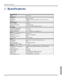
1
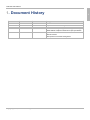
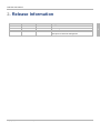
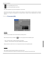
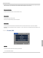
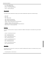
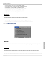
TPG-2000 User Manual
Table of Contents
Document History
1
Release Information
2
Disclaimer
3
Foreword
4
Important Information
5
Avoiding Personal Injury
5
Power Supply
5
Installation Environment
5
Operating Temperature
5
Input/Output Terminals
5
When Not In Use
6
Maintenance
6
Warranty
Warranty Exceptions
Overview
Mechanical Layout
6
6
7
7
Top Panel
7
Left Panel
8
Right Panel
8
Features
Video standards
9
9
Test Patterns
10
3D Modes
10
Overlays
10
ANC Data
11
Embedded Audio
11
Web Server
11
Genlock
11
SD Card
11
Copyright (c) 2013, DELTACAST. All rights reserved.
ii
TPG-2000 User Manual
Operation
12
Basic Usage
12
Menus
14
Out A - Out B
14
Pattern (1/8)
14
Timecode (2/8)
19
Format (3/8)
20
Meta Data (4/8)
22
Audio Group (5,6,7,8/8)
24
Settings
25
Network (1/2)
25
Others (2/2)
27
Info
28
Revision (1/4)
28
Diagnostic (2,3,4/4)
28
Advanced Usage
User Patterns
29
29
Standard Single Link Pattern Generation
30
3D Single Link Pattern Generation
30
3D Dual Link Pattern Generation
31
3D Modes
31
Quad-HD/3G Formats
33
Firmware Upgrade
34
Web Server
34
Specifications
Index
Copyright (c) 2013, DELTACAST. All rights reserved.
35
a
iii
TPG-2000 User Manual
1. Document History
1
Revision Date
Document Version
Software Version
Changes
2013-04-05
v1.0
v02.00.0000
First release
2013-04-30
v1.1
v02.00.0100
Adaptation due to minor changes in GUI
2013-06-21
v1.2
v02.00.0100
Bitrate variation range changed from +/-25ppm to +/-50ppm
Added SMPTE compliance statement for jitter specification
2013-09-04
v1.3
v02.02.0000
Update due to new SW release:
- New 4K formats
- New options for timecode management
Copyright (c) 2013, DELTACAST. All rights reserved.
1
TPG-2000 User Manual
2. Release Information
Revision Date
Software Release
Hardware Release
Changes
2013-04-05
v02.00.0000
v02.00.0005
First release
2013-04-24
v02.00.0100
v02.00.0007
Minor changes in GUI
2013-09-04
v02.02.0000
v02.00.0007
New 4K formats
New options for timecode management
Copyright (c) 2013, DELTACAST. All rights reserved.
2
2
TPG-2000 User Manual
3. Disclaimer
Copyright © DELTACAST.TV SA. All rights reserved. Software products licensed are owned by DELTACAST.TV SA and are
protected by international treaty provisions and national copyright laws.
No part of this document may be reproduced, stored or transmitted in any form without the prior written consent of
DELTACAST.TV SA.
DELTACAST.TV SA does not assume responsibility for loss or damage resulting from errors, omissions or inaccuracies
herein. DELTACAST.TV SA products are not authorized for use in safety-critical applications (such as life support) where a
failure of the DELTACAST.TV SA product would reasonably be expected to cause severe personal injury or death.
3
DELTACAST.TV SA reserves the right to make corrections, modifications, enhancements, improvements and other changes
to this document at any time without notice.
Copyright (c) 2013, DELTACAST. All rights reserved.
3
TPG-2000 User Manual
4. Foreword
Thank you for choosing TPG-2000, the universal 3G/HD/SD SDI test pattern generator.
This documentation contains all the information needed to operate the device. It explains the different panels layout, details
the product features and menus, and covers advanced functionalities such as user patterns loading and firmware upgrade.
Please carefully read this guide before operating the TPG-2000.
4
Copyright (c) 2013, DELTACAST. All rights reserved.
4
TPG-2000 User Manual
5. Important Information
5.1. Avoiding Personal Injury
• The unit must only be operated by qualified person who has read the user manual.
• The unit enclosure should not be removed.
• Unit should not be exposed to water or liquids.
• Unit should be returned to DELTACAST.TV for repair or servicing.
5.2. Power Supply
Make sure that the unit is connected to the correct power supply voltage. A power supply adaptor is supplied with the unit,
and must be connected to any AC power supply between 100 and 240VAC at 50-60Hz.
• Only use the power adapter supplied with the unit.
• Unit voltage and current ratings are indicated on the nameplate located on the back side of the unit.
• Unplug the unit from the wall outlet if it is not to be use for an extended period of time.
• To disconnect the cord, pull it out by the plug, never pull the cord itself.
• Do not expose the unit to water.
• Do not use a damaged AC cable with the unit as it may cause a shock or fire hazard.
5
5.3. Installation Environment
5.3.1. Operating Temperature
The unit should only be operated between 0 and 40° C (32 to 104° F). If the unit is operated at a higher temperature there is
a possibility of a fire hazard. If the temperature is changed rapidly from a cold environment to a hot environment, moisture
can be created internally which can cause malfunction or damage the unit.
5.3.2. Input/Output Terminals
Do not connect the input or output BNC connectors to external power as this can damage the internal circuitry and cause the
unit to work incorrectly.
Copyright (c) 2013, DELTACAST. All rights reserved.
5
TPG-2000 User Manual
5.3.3. When Not In Use
Disconnect the unit from the power supply and AC power source when not in use.
5.3.4. Maintenance
Use a slightly damp cloth to clean the unit enclosure. Only neutral cleaning agent should be used. Internal parts must not be
exposed to water or liquids. LCD screen can be cleaned softly with a LCD screen cleaning solution. A screen cleaning cloth
may be used to clean the LCD. Do not apply force to the LCD when cleaning, this could damage the unit.
Turn OFF and remove the power supply from the unit before cleaning.
5.4. Warranty
DELTACAST.TV SA warrants that its products will perform substantially in accordance with the accompanying written
materials for a period of 1 year from the date of receipt and that the product will be free from defects in materials and
workmanship under normal use and service for a period of 1 year.
5.4.1. Warranty Exceptions
DELTACAST.TV SA is not responsible for free service during the warranty period under the following conditions:
5
• Incorrect voltage applied to unit.
• Incorrect power adaptor used.
• Fire, natural disaster.
• Repair of instrument by non DELTACAST.TV approved agent.
• Repair of damage caused by third party products.
• Repair of damage caused by improper use.
• Repair without proof of purchase.
Copyright (c) 2013, DELTACAST. All rights reserved.
6
TPG-2000 User Manual
6. Overview
The TPG-2000 is a 3G/HD/SD SDI test pattern generator.
It hosts 4 SDI output connectors organized as two pairs of channels named Out A and Out B. The same signal is emitted on
both outputs of each pair, and the TPG-2000 is able to simultaneously generate independent patterns on each pair.
The TPG-2000 can be genlocked onto an analog SD/HD reference signal thanks to its black burst input named Ref in.
6.1. Mechanical Layout
6.1.1. Top Panel
6
The top panel has the following interfaces:
• Touchscreen - LCD monitor with touchscreen to control the user interface
• Status LED - Used as Power LED (Blue) and Hardware Failure LED (Red)
Copyright (c) 2013, DELTACAST. All rights reserved.
7
TPG-2000 User Manual
6.1.2. Left Panel
The left panel has the following interfaces:
• Pwr - Connector for the power adapter module. Connect to the supplied +5V DC power supply unit.
• Off/On - Rocker style power switch to turn On or Off the TPG-2000 unit.
• SD card - SD memory card slot to load user patterns and for firmware updates.
• USB - USB Type B connector (for future use).
• LAN - Ethernet connector (RJ-45) for remote control.
• Reset - Unit master reset (pinhole under SD card slot).
6.1.3. Right Panel
6
The right panel has the following interfaces:
• Out A - 2x BNC 75 Ohm: SDI output connectors (same SDI signal on both connectors)
• Out B - 2x BNC 75 Ohm: SDI output connectors (same SDI signal on both connectors)
• Ref in - BNC 75 Ohm: Tri-Level or Bi-Level (black burst) sync input.
Copyright (c) 2013, DELTACAST. All rights reserved.
8
TPG-2000 User Manual
6.2. Features
6.2.1. Video standards
The TPG-2000 is compliant with these SDI interface standards:
• SMPTE 259M-C (SD - 270 Mbps)
• SMPTE 292M (HD - 1.485 & 1.485/1.001 Gbps)
• SMPTE 425M-A (3G Level A – 2.97 & 2.97/1.001 Gbps)
Supported output formats are given here below:
6
Copyright (c) 2013, DELTACAST. All rights reserved.
9
TPG-2000 User Manual
6.2.2. Test Patterns
• User File
• Color Field (color configurable)
• 75% Color Bars
• SMPTE Bars
• Grey Step V (number of steps configurable)
• Grey Step H (number of steps configurable)
• Check Field
• Equalizer Test
• PLL Test
• Luma Ramp
• Chroma Ramp
• Multiburst
• Cross-Hatch
• Target
• Filled Target
• 3D L-R
6.2.3. 3D Modes
3D patterns can be generated by a provided user pattern generator application. The available 3D modes are the following:
• Line by Line
• Side by Side
• Checkerboard
6
• Top/Bottom
• Full 3D (3D Dual Link)
6.2.4. Overlays
• Timecode (Fixed or Moving)
• Black or White Square (Fixed, Moving or Deformable)
Copyright (c) 2013, DELTACAST. All rights reserved.
10
TPG-2000 User Manual
6.2.5. ANC Data
• EDH (HANC - SD only)
• SMPTE 352M VPID (HANC)
• D-VITC Time Code (VBI - SD only)
• ATC Time Code (VANC)
• CEA-608 Closed-Caption (VBI - NTSC only)
• Misc. VANC packet (Fixed payload - Frame counter and 8-bit counter)
6.2.6. Embedded Audio
• 16 audio channels in 4 audio groups
• SMPTE 272M (SD) and SMPTE 299M (HD/3G) compliant
• 24-bit resolution in HD/3G, 20-bit resolution in SD
• 48kHz sample frequency, video synchronous
• Independent control for each channel (enable, frequency, attenuation)
• Independent audio group enable
• Frequency range: 20Hz to 22kHz in 10Hz steps
• Attenuation range: 0dB to 140dB in 1dB steps
• AES Channel Status data support
6.2.7. Web Server
The TPG-2000 can be remote controlled from a web browser.
6
6.2.8. Genlock
• Bi-Level/Tri-Level analog references support
• Configurable offset (alignment offset of an output with respect to the input reference)
• Free-run mode with programmable bitrate variation (range: +/- 50ppm)
6.2.9. SD Card
SD memory cards are used for User Patterns upload and for firmware upgrade.
Maximum supported capacity for SD cards is 4GB. SDHC cards are not supported.
Copyright (c) 2013, DELTACAST. All rights reserved.
11
TPG-2000 User Manual
7. Operation
7.1. Basic Usage
Your TPG-2000 comes ready-to-use. Take it out of its packing and place it on a flat and stable surface. Connect the power
supply unit and screw connector for added security.
Put the rocker style power switch to "On" to power up your TPG-2000 and wait for the system to boot. Toggling back the
power switch to "Off" will turn your TPG-2000 off.
TPG-2000 user interface is a color touch screen display. A single touch will activate an item on the screen or take you down
to a lower level menu. Using a stylus is recommended for more precise control of the interface but it is not necessary.
The user interface is organized into three zones: upper band, lower band and main page as illustrated here below.
Upper band:
The upper band consists of four buttons:
• Out A
7
• Out B
• Settings
• Info
These buttons are always visible at any time and correspond to a group of settings/information.
Copyright (c) 2013, DELTACAST. All rights reserved.
12
TPG-2000 User Manual
Lower band:
In each group, the settings/information are split into pages. Navigation between these pages is controlled using the arrows
located in the lower band. The name of the current page and the number of pages into the group are also displayed in the
same lower band.
The lower band is also used as a status bar. It indicates the genlock status when enabled and displays an hourglass when
an update of the parameters is in progress.
Main page:
The main page area brings together all the controls and options related to the selected page.
The organization of the different groups and the related pages is given in the next topics.
The various parameters are selected using checkboxes or local menu with arrows.
7
The numerical parameters are directly modified using a virtual numeric keyboard.
Copyright (c) 2013, DELTACAST. All rights reserved.
13
TPG-2000 User Manual
The value can be validated using the button with a green V-shaped picture. The last digit can be deleted using the button in
the middle with the blue arrow going backwards and finally, this menu may be exited without affecting the current value using
the blue undo button on the right.
7.2. Menus
7.2.1. Out A - Out B
7.2.1.1. Pattern (1/8)
7
Pattern:
This selects the video pattern that is output by the TPG-2000. The unit provides some standard patterns but you may also
download your own test patterns to the generator using an SD card. The user pattern is then available as the "User File"
pattern. When applicable, the
button on the right of the pattern name gives access to pattern options.
Copyright (c) 2013, DELTACAST. All rights reserved.
14
TPG-2000 User Manual
Name
User File
Pattern
User generated pattern
Color Field
Option: Color
75% Color Bars
SMPTE Bars
Grey Step V
Option: Number of steps
Grey Step H
Option: Number of steps
Check Field
EQ Check
PLL Check
7
Luma Ramp
Copyright (c) 2013, DELTACAST. All rights reserved.
15
TPG-2000 User Manual
Chroma Ramp
Multiburst
Cross-Hatch
Target
Filled Target
3D L-R
Moving Object:
A moving black square (or a white one) may be overlaid on the current test pattern by selecting the right value on this menu:
• No Animation - No overlay
• Black Square - Add a black square overlay
• White Square - Add a white square overlay
7
When an overlay is selected, the
button on the right gives access to the moving object options.
The options are:
• Translation - Moving square (user definable position and speed)
• Deformed Translation - Moving rectangle with variable size (user definable position and speed)
Copyright (c) 2013, DELTACAST. All rights reserved.
16
TPG-2000 User Manual
Setting the speed to 0 allows to have a non-moving overlay with an adjustable position.
Enable:
Output can be enabled or disabled on the fly with this checkbox.
3D Dual:
This option is only available for Out A group. Checking this box activates the full 3D mode.
When activated, the parameters of the output A overwrite those of output B.
If you use a full 3D user pattern (generated by the User File generator with the "Full-3D" option), then the output stream A
will be the left stream while the output stream B will be the right one.
If you use a standard pattern (standard patterns available on the TPG-2000), this pattern will be replicated on the two
outputs.
Finally, if you use a non-full 3D user pattern (generated by the User File generator with the "Half-3D" option), this pattern will
be output on stream A while the output stream B pattern is a black frame.
Genlock:
The generator may be synchronized to an input reference signal, which may be a Bi-Level or Tri-Level sync signal.
Alternatively, the generator may free run.
Cross-genlocking (different frame rate between black burst reference and selected output) is possible, but an European (EU)
output cannot be genlocked on an American (US) reference and vice versa.
The supported reference formats are listed below:
• NTSC, 525i
• PAL, 625i
7
• 525p
• 625p
• 720p/60
• 720p/59.94
• 720p/50
• 720p/30
• 720p/29.97
Copyright (c) 2013, DELTACAST. All rights reserved.
17
TPG-2000 User Manual
• 720p/25
• 720p/24
• 720p/23.98
• 1080p(PsF)/30
• 1080p(PsF)/29.97
• 1080p(PsF)/25
• 1080p(PsF)/24
• 1080p(PsF)/23.98
• 1080i/60
• 1080i/59.94
• 1080i/50
Genlock control is independent for each output. However, if genlock is enabled in one output, video clock frequency of the
other output will also be genlocked but without frame alignment.
Genlocking the two outputs is possible without black burst reference. Just enable genlock on each output and they will be
frame aligned (Cross-genlocking between EU and US frame rates is not supported).
The
button on the right gives access to additional options:
• Bitrate Control Enable - Enable programmable bitrate variation (common to both outputs - automatically disables genlock
on the input reference)
• VCXO Control - Set the variation from the base bitrate (in the range of 0 to 1023, respectively -50 / +50 ppm)
• Genlock Offset - Set the offset of the output with respect to the reference input.
The offset is entered as a number of pixels (range: 0 to 4 194 303 pixels) of the output stream. Output is then delayed by this
amount of pixels. Negative offset has to be entered by subtracting the offset to the number of pixels per frame, including the
blankings.
The genlock status of both outputs is always available on the status bar (lower band). The lock pictogram is present when
genlock is enabled on at least one output. There is a small delay (a few seconds) before the status is updated when
changing some settings and/or changing the input reference.
7
The meaning of the different pictograms is explained hereafter:
•
- All outputs unlocked (Ref. input is EU or no reference is present)
•
- All outputs unlocked (Ref. input is US)
•
- Out A is genlocked (Ref. input is EU)
•
Copyright (c) 2013, DELTACAST. All rights reserved.
18
TPG-2000 User Manual
- Out A is genlocked (Ref. input is US)
•
- Out A & B are genlocked (Ref. input is US)
Some other combinations of the previous examples are not shown here.
One should note that when using the 3D Dual Link mode without an external reference, the genlock status is 'Unlocked'
because the two outputs are not genlocked on the output reference. However, they are still genlocked on the internal
reference.
7.2.1.2. Timecode (2/8)
Timecode:
A timecode may be overlaid on the current test pattern by checking this box.
When the timecode overlay is enabled, the
button on the right gives access to additional options:
• Fixed - Timecode overlay is centered at the bottom of the pattern
• Translation - Timecode overlay is moving (user definable position and speed)
7
Setting the speed to 0 allows to have a non-moving timecode overlay with an adjustable position.
Loop back:
When selected, this option enables boundaries for the timecode value.
The timecode will be reset to the value set in "Start Timecode" when it reaches the "End Timecode" value.
Copyright (c) 2013, DELTACAST. All rights reserved.
19
TPG-2000 User Manual
If disabled, the timecode will start at the "Start Timecode" value but will only wrap to 00:00:00:00 at the maximum timecode
value of 23:59:59:xx. (xx is the last frame of the selected format and depends on the frame rate)
Reset current timecode:
This button resets the timecode to the "Start Timecode" value.
Start Timecode:
This is the start value for the timecode.
The button on the right resets this value to 00:00:00:00.
End Timecode:
This is the end value for the timecode. The timecode is reset to the "Start Timecode" value if "Loop back" is enabled.
The button on the right resets this value to 23:59:59:xx. (xx is the last frame of the selected format and depends on the
frame rate)
7.2.1.3. Format (3/8)
7
Link type:
This selects the video interface that is output by the TPG-2000.
• SD - SD-SDI SMPTE 259M-C
Copyright (c) 2013, DELTACAST. All rights reserved.
20
TPG-2000 User Manual
• HD - HD-SDI SMPTE 292M
• 3G-A - 3G-SDI SMPTE 425M-A
• UHDTV-1 - Quad-1080p HD/3G-SDI
• 4K-DCI - Quad-2K HD/3G-SDI
Video standard:
This selects the video standard that is output by the TPG-2000. Available values depend on the selected Link type.
• 480i - NTSC
• 576i - PAL
• 720p - SMPTE 296M
• 1080i - SMPTE 274M (interlaced)
• 1080p - SMPTE 274M (progressive)
• 1080psf - SMPTE 274M (progressive segmented frame)
• 1080p(2K) - SMPTE ST-2048-2 (progressive)
• 1080psf(2K) - SMPTE ST-2048-2 (progressive segmented frame)
• 2160p - UHDTV-1 / 4K-DCI (progressive)
Frame rate:
This selects the frame rate that is output by the TPG-2000. Available values depend on the selected Link type and Video
standard.
• 23.98 Hz - 23.98 frames per second
• 24 Hz - 24 frames per second
• 25 Hz - 25 frames per second
• 29.97 Hz - 29.97 frames per second
• 30 Hz - 30 frames per second
• 47.95 Hz - 47.95 frames per second
• 48 Hz - 48 frames per second
• 50 Hz - 50 frames per second
• 59.94 Hz - 59.94 frames per second
• 60 Hz - 60 frames per second
7
Color format:
This selects the color format that is output by the TPG-2000. Available values depend on the selected Link type, Video
standard and Frame rate.
• 4:2:2 (YCbCr)/10-bit - 10-bit 4:2:2 YUV
Copyright (c) 2013, DELTACAST. All rights reserved.
21
TPG-2000 User Manual
• 4:4:4 (YCbCr)/10-bit - 10-bit 4:4:4 YUV, only available in 3G-SDI
• 4:4:4:4 (YCbCr+K)/10-bit - 10-bit 4:4:4:4 YUVK, only available in 3G-SDI
• 4:4:4 (RGB)/10-bit - 10-bit 4:4:4 RGB, only available in 3G-SDI
• 4:4:4:4 (RGB+A)/10-bit - 10-bit 4:4:4:4 RGBA, only available in 3G-SDI
• 4:2:2 (YCbCr)/12-bit - 12-bit 4:2:2 YUV, only available in 3G-SDI
• 4:4:4 (YCbCr)/12-bit - 12-bit 4:4:4 YUV, only available in 3G-SDI
• 4:4:4 (RGB)/12-bit - 12-bit 4:4:4 RGB, only available in 3G-SDI
Mirroring types:
This selects the patterns' mirroring type for the UHDTV-1 and 4K-DCI formats.
• Vertical Mirroring - Out A is the left part of the frame, Out B is the right part of the frame
• Horizontal Mirroring - Out A is the top part of the frame, Out B is the bottom part of the frame
7.2.1.4. Meta Data (4/8)
SMPTE 352M:
This checkbox enables or disables insertion of the SMPTE 352M Video Payload ID packet(s) into the video output stream.
7
VANC Counter:
This checkbox enables or disables insertion of a custom ANC packet in the VANC space of the video output stream.
The content of the ANC packet is given hereafter as 8-bit hex values. These are the least significant bits (0 to 7) of the 10-bit
Copyright (c) 2013, DELTACAST. All rights reserved.
22
TPG-2000 User Manual
SDI interface. Bit 8 is a parity bit (even parity) and bit 9 is bit 8 inverted.
• DID is set to 0x54
• SDID is set to 0xAC
• DC is always equal to 0x84
• UDW0 to UDW2 is a 24-bit frame counter (automatically wraps to 0 - UDW0 being the MSB)
• UDW3 is set to 0x00 for field 1 an to 0xFF for field 2
• UDW4 to UDW131 is an 8-bit counter that starts at 0x00 and automatically wraps at 0xFF (spans two fields/frames)
The packet is inserted on lines 15 & 278 for NTSC, lines 11 & 324 for PAL and on lines 12 (& 574) for HD/3G formats.
ATC Time Code VANC:
This checkbox enables or disables insertion of the ANC Time Code ANC packet.
The ATC packet conveys a VITC Time Code, which has the same value as the D-VITC Time Code and overlay, if enabled.
The ATC packet is inserted two lines after the switching line. This means lines 12 & 275 for NTSC, lines 8 & 321 for PAL and
lines 9 (& 571) for HD/3G formats.
D-VITC Time Code VBI (SD only):
This checkbox enables or disables insertion of the Digital Video Interval Time Code in the VBI space.
The D-VITC Time Code has the same value as the ATC Time Code and the overlay, if enabled.
D-VITC is inserted on lines 14 & 277 for NTSC and on lines 19 & 332 for PAL.
CEA-608 Closed-Caption VBI (NTSC only):
7
This checkbox enables or disables insertion of the CEA-608 Closed-Caption in the VBI space.
Only CC1 data channel is present, thus no CC data is inserted on field 2.
Closed-Caption data corresponds to the display of "DELTACAST" at the bottom of the screen for ~2,5 seconds and then
clearing the caption for ~1 second. Then, the sequence starts over.
Copyright (c) 2013, DELTACAST. All rights reserved.
23
TPG-2000 User Manual
CEA-608 is inserted on line 21.
7.2.1.5. Audio Group (5,6,7,8/8)
Enable Group:
Checking this box separately enables each of the four SDI audio groups.
Left or Right:
Checking this box separately enables each of the channels.
Frequency:
This allows selection of embedded audio channel tone frequency. (in the range of 20Hz to 22kHz by 10Hz steps)
7
Attenuation:
This allows selection of embedded audio channel attenuation. (in the range of 0 to 140dB)
Link:
Copyright (c) 2013, DELTACAST. All rights reserved.
24
TPG-2000 User Manual
This links the left and right channels of a pair so that changing the attenuation on the left channel changes the level on the
right channel.
7.2.2. Settings
7.2.2.1. Network (1/2)
TPG-2000 is fully networkable and has a complete network interface.
If you have a DHCP server on your network, check the DHCP Enable box and an IP address will be assigned automatically.
If you need use a static address, you will need to enter manually your IP Address, your IP Mask and your Gateway.
DHCP Enable:
This enables Dynamic Host Configuration Protocol.
MAC Address:
7
This shows the MAC address of the TPG-2000.
IP Address / IP Mask / Gateway:
This allows you to enter your network settings if you do not use DHCP. A value must be attributed for each parameter: IP
Address, IP Mask and Gateway.
Copyright (c) 2013, DELTACAST. All rights reserved.
25
TPG-2000 User Manual
Tap on an address to change it. It gives access to the following menu, where you can edit the value.
7
Copyright (c) 2013, DELTACAST. All rights reserved.
26
TPG-2000 User Manual
7.2.2.2. Others (2/2)
Reset to factory settings:
This button resets the TPG-2000 to the factory default settings. A confirmation will be prompted. If confirmed, the TPG-2000
will automatically reboot to apply the default settings.
Touchscreen calibration:
This button gives access to the calibration of the touchscreen. Touchscreen calibration may be needed after some times if
the interface seems to have lost precision. A confirmation will be prompted.
Use a stylus or a pen and precisely tap on the different targets that will appear to do the calibration.
Screen saver wait:
Tap on the number to change the delay before the screen saver appears. The minimum is 1 minute and the maximum is 60
minutes.
7
Copyright (c) 2013, DELTACAST. All rights reserved.
27
TPG-2000 User Manual
7.2.3. Info
7.2.3.1. Revision (1/4)
This page shows the serial number and the hardware and software version information.
7.2.3.2. Diagnostic (2,3,4/4)
These pages show system voltages and temperatures.
7
Copyright (c) 2013, DELTACAST. All rights reserved.
28
TPG-2000 User Manual
7.3. Advanced Usage
7.3.1. User Patterns
The TPG-2000 allows users to create their own test patterns. Simply create the ubm file with the application (see below) and
place them on the SD card (do not rename the generated files, keep the name as UserFile_x_y.ubm where x and y are
numbers). The TPG-2000 will scan the SD card and will ask you to download all user files from SD card a few seconds later.
The download process takes 15 - 30 seconds, depending of the number of formats generated. A hourglass is displayed on
the status bar during the download process.
Only one User Pattern is supported for the time being. It is however available in all formats.
Copyright (c) 2013, DELTACAST. All rights reserved.
7
29
TPG-2000 User Manual
Once downloaded, you can access to your pattern via the choice of pattern menu, even if you remove the SD card.
The user patterns are generated using an application provided by DELTACAST.TV. You can download it at the following
address: http://www.deltacast.tv/.
7.3.1.1. Standard Single Link Pattern Generation
To generate a standard single link pattern:
• Choose a source file in bitmap format using the button “Choose source file L” (The dimensions of the source files do not
matter but for best results, use an image whose dimensions are those of the active image of format you wish to use).
• Check one or more checkboxes corresponding to the output format you want
• Choose a destination directory using the button “Choose Destination folder”
• Click on the Generate button.
• The ubm files generate will be available on your destination folder.
These user patterns can be used interchangeably on A or B outputs.
7.3.1.2. 3D Single Link Pattern Generation
To generate a 3D single link pattern:
• Choose a source file in bitmap format for the left eye using the button “Choose source file L” (The dimensions of the
source files do not matter but for best results, use an image whose dimensions are those of the active image of format
you wish to use).
7
• Choose a source file in bitmap format for the right eye using the button “Choose source file R” (The dimensions of the
source files do not matter but for best results, use an image whose dimensions are those of the active image of format
you wish to use).
• Check one or more checkboxes corresponding to the output format you want
• Choose one of the Half 3D mode that you will use: Line by Line, Side by Side, CheckerBoard or Top/Bottom
• Choose a destination directory using the button “Choose Destination folder”
• Click on the Generate button.
• The ubm files generate will be available on your destination folder.
Copyright (c) 2013, DELTACAST. All rights reserved.
30
TPG-2000 User Manual
These user patterns can be used interchangeably on A or B outputs.
7.3.1.3. 3D Dual Link Pattern Generation
To generate a 3D dual link pattern:
• Choose a source file in bitmap format for the left eye using the button “Choose source file L” (The dimensions of the
source files do not matter but for best results, use an image whose dimensions are those of the active image of format
you wish to use).
• Choose a source file in bitmap format for the right eye using the button “Choose source file R” (The dimensions of the
source files do not matter but for best results, use an image whose dimensions are those of the active image of format
you wish to use).
• Check one or more checkboxes corresponding to the output format you want
• Choose the Full 3D mode : Side by Side
• Choose a destination directory using the button “Choose Destination folder”
• Click on the Generate button.
• The ubm files generate will be available on your destination folder.
These user patterns can be used only on A output with the 3D Dual Link enable option activated.
7.3.2. 3D Modes
The different 3D single link modes available are:
• Line by Line
7
• Side by Side
Copyright (c) 2013, DELTACAST. All rights reserved.
31
TPG-2000 User Manual
• CheckerBoard
• Top/Bottom
The full 3D dual link mode available is:
• Full 3D Dual Link mode
7
Copyright (c) 2013, DELTACAST. All rights reserved.
32
TPG-2000 User Manual
7.3.3. Quad-HD/3G Formats
The UHDTV-1 and 4K-DCI formats use the 4 outputs present on the TPG-2000 to generate the 4 1080p/2K quadrants
needed to construct a complete frame.
Two mirroring options are available to generate as more different patterns as possible:
• Vertical Mirroring
The patterns available in this mode are the following: Color Field, 75% Color Bars, Grey Step H, Equalizer Test, PLL Test,
Luma Ramp, Multiburst and Cross-Hatch.
• Horizontal Mirroring
7
The patterns available in this mode are the following: Color Field, Grey Step V, Check Field, Equalizer Test, PLL Test,
Cross-Hatch.
Copyright (c) 2013, DELTACAST. All rights reserved.
33
TPG-2000 User Manual
7.3.4. Firmware Upgrade
Firmware upgrade is only possible with a SD Card for the time being.
To upgrade, put the provided binary file on a SD card. A few seconds after insertion of the card into the TPG-2000 with a
valid binary file, a pop-up will ask to launch the upgrade process. Update takes approximately 15 seconds. The TPG-2000
then automatically reboots on the new firmware.
Do not remove the SD card before the upgrade process is finished!
7.3.5. Web Server
The webserver enables remote control of the TPG-2000. All properties of the TPG-2000 are available on the webserver. It is
accessible with a web browser by entering the TPG-2000 IP address. You can find its IP address on the Network page (1/2)
of the Settings menu.
Remark: Firefox is not supported.
7
Copyright (c) 2013, DELTACAST. All rights reserved.
34
TPG-2000 User Manual
8. Specifications
8
Copyright (c) 2013, DELTACAST. All rights reserved.
35
TPG-2000 User Manual
Index
3
3D Dual Link Pattern Generation 31
3D Modes 10, 31
3D Single Link Pattern Generation 30
L
Left Panel 8
M
Maintenance 6
Mechanical Layout 7
A
Menus 14
Meta Data (4/8) 22
Advanced Usage 29
ANC Data 11
Audio Group (5,6,7,8/8) 24
Avoiding Personal Injury 5
B
Basic Usage 12
N
Network (1/2) 25
O
Operating Temperature 5
Operation 12
D
Diagnostic (2,3,4/4) 28
Disclaimer 3
Others (2/2) 27
Out A - Out B 14
Overlays 10
Overview 7
Document History 1
E
Embedded Audio 11
F
Features 9
P
Pattern (1/8) 14
Power Supply 5
Q
Quad-HD/3G Formats 33
Firmware Upgrade 34
Foreword 4
Format (3/8) 20
R
Release Information 2
G
Revision (1/4) 28
Right Panel 8
Genlock 11
I
Important Information 5
Info 28
Input/Output Terminals 5
S
SD Card 11
Settings 25
Specifications 35
Standard Single Link Pattern Generation 30
Installation Environment 5
Copyright (c) 2013, DELTACAST. All rights reserved.
a
TPG-2000 User Manual
T
Test Patterns 10
Timecode (2/8) 19
Top Panel 7
U
User Patterns 29
V
Video standards 9
W
Warranty 6
Warranty Exceptions 6
Web Server 11, 34
When Not In Use 6
Copyright (c) 2013, DELTACAST. All rights reserved.
b