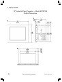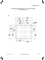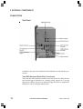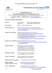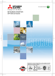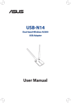
1
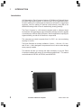
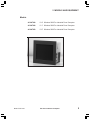
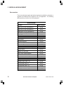
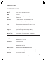
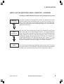
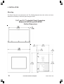
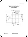
INDUSTRIAL FLAT
PANEL COMPUTERS
(Manual Part Number MAN-UTPPC-002)
WARNING!
Programmable control devices such as the Industrial Flat Panel Computers must not be used as stand-alone
protection in any application. Unless proper safeguards are used, unwanted start-ups could result in equipment damage or personal injury. The operator must be made aware of this hazard and appropriate precautions
must be taken.
In addition, consideration must be given to the use of an emergency stop function that is independent of the
programmable controller.
The diagrams and examples in this user manual are included for illustrative purposes only. The manufacturer
cannot assume responsibility or liability for actual use based on the diagrams and examples.
CAUTION
Do not press the Panel Computer touchscreen with any sharp objects. This practice may damage the unit
beyond repair.
Trademarks
This publication may contain references to products produced and/or offered by other companies. The
product and company names may be trademarked and are the sole property of their respective owners.
AVG Automation disclaims any proprietary interest in the marks and names of others.
Manual P/N MAN-UTPPC-002
© Copyright 2003, AVG Automation
All Rights Reserved
No part of this manual shall be copied, reproduced, or transmitted in any way without the prior written
consent of AVG Automation. AVG Automation retains the exclusive rights to all information included in this
document.
AVG Automation
4140 Utica Ridge Rd. • Bettendorf, IA 52722-1327
Phone: 1-563-359-7501 • Fax: 1-563-359-9094 • www.avg.net
CONTENTS
CHAPTER 1 INTRODUCTION
Manual Organization .............................................................................
Introduction ...........................................................................................
What you need to get started ...............................................................
Technical Support .................................................................................
1
2
3
3
CHAPTER 2 MODELS AND EQUIPMENT
Models ................................................................................................... 5
Accessories ........................................................................................... 6
CHAPTER 3 SPECIFICATIONS
Specifications ........................................................................................ 7
CHAPTER 4 INSTALLATION
Installing the Industrial Panel Computer — Overview ......................... 9
Mounting ............................................................................................. 10
10.4" and 12.1" Industrial Panel Computers
Models ACCAT220 and ACCAT240 Outline Dimensions ........... 10
10.4" and 12.1" Industrial Panel Computers
Models ACCAT220 and ACCAT240 Cutout Dimensions ............. 11
15" Industrial Panel Computer — Model ACCAT250
Outline Dimensions ..................................................................... 12
15" Industrial Panel Computer — Model ACCAT250
Cutout Dimensions ...................................................................... 13
CHAPTER 5 EXTERNAL COMPONENTS
Connectors .......................................................................................... 14
CHAPTER 6 COMMUNICATIONS SETUP
BIOS Setup ......................................................................................... 19
COM2 Serial Port Setup ..................................................................... 19
CHAPTER 7 MAINTENANCE AND UPGRADES
Upgrades ............................................................................................. 20
Expansion Card Installation ............................................................. 20
Maintenance ....................................................................................... 23
Preserving Data ............................................................................... 23
Touchscreen/Display ....................................................................... 23
Touchscreen/Chemical Compatibility .............................................. 24
Touchscreen Cleaning ..................................................................... 24
MAN-UTPPC-002
Flat Panel Industrial Computer
i
CONTENTS
This page intentionally left blank.
ii
Flat Panel Industrial Computer
MAN-UTPPC-002
1 INTRODUCTION
Manual Organization
The table, below provides an overall description of the topics covered within this manual.
Sections
1
2
3
Introduction
Provides Manual Organization, and lists what you need
to get started. Discusses how to get help with questions
or problems you might encounter through Technical
Support.
Models and
Equipment
Provides you with a table listing the various models,
their part numbers and features. Lists the optional
equipment available.
Specifications
Specifications provide detailed information. Included
are display size, connector and expansion card
information, CPU type; service power requirements;
operating and storage temperatures; available memory;
serial communications specs; dimensions, weight, etc.
4
Installation
Shows the mounting and cutout dimensions for the
panel models.
5
External
Components
Provides location and description of the available
connectors and expansion card slots. Provides location
and description of switches, push buttons, display
brightness potentiometer, and LEDs. Discusses
Communication Setup.
BIOS Setup
Consult PCA1675 Embedded Processor Board User
Manual, Part Number MAN-P1675-002.
Maintenance and
Upgrades
Step-by-step instructions to install an expansion card
are provided. Provides basic maintenance tasks to
preserve data. Describes cleaning of touch screen and
housing. Lists chemicals that may or may not be
compatible with the touchscreen.
6
7
MAN-UTPPC-002
Flat Panel Industrial Computer
1
1
INTRODUCTION
Introduction
AVG Automation’s Panel Computer features a 700 Mhz Intel Pentium/Celeron
processor single board computer, in various sizes to fit your application needs.
An active matrix LCD, resistive-type touchscreen is mounted in a rugged steel
enclosure, with Zinc plating for optimum noise immunity, along with a flat
NEMA4/4X sealing bezel to form an aesthetically pleasing package.
The Panel Computer is a full featured computer able to withstand harsh
environments. Its rugged design, high performance and easy access for upgrade
or maintenance make the Panel Computer ideal for applications requiring the
highest reliability, as with all AVG electronic components.
The computers are rated to operate from 0 to 50ºC, at a non-condensing
humidity of 10–95%.
The Panel Computer is currently available in 3 sizes — 10.4-inch, 12.1-inch,
and 15-inch — and is designed to be protected from oil, dust or water damage
when properly installed.
This manual will take you through the steps necessary to get your Panel
Computers installed and running in the shortest possible time. This manual
covers Models ACCAT220, ACCAT240, and ACCAT250.
2
Flat Panel Industrial Computer
MAN-UTPPC-002
1 INTRODUCTION
What you need to get started:
Hardware
•
Industrial Panel Computer Series:
ACCAT220 — 10.4-inch Windows 2000 Pro
ACCAT240 — 12.1-inch Windows 2000 Pro
ACCAT250 — 15-inch Windows 2000 Pro
Software
•
Windows 2000 Pro
Technical Support
Technical Support
If you are having difficulty with a particular aspect of installation or setup,
technical support is available at 1-800-832-3647 or FAX us at 1-563-3599094.
MAN-UTPPC-002
Flat Panel Industrial Computer
3
1
INTRODUCTION
This page intentionally left blank.
4
Flat Panel Industrial Computer
MAN-UTPPC-002
2 MODELS AND EQUIPMENT
Models
MAN-UTPPC-002
ACCAT240
10.4” Windows 2000 Pro Industrial Panel Computer
ACCAT240
12.1” Windows 2000 Pro Industrial Panel Computer
ACCAT250
15.0” Windows 2000 Pro Industrial Panel Computer
Flat Panel Industrial Computer
5
2 MODELS AND EQUIPMENT
Accessories
There are replacement parts and optional equipment available to customize or
upgrade the Industrial Panel Computer to fit your application. The following
tables provide you with a list of this equipment.
Accessories
Product
6
Part Number
32MB Disk on Chip Flash Memory
AC600
64MB Disk on Chip Flash Memory
AC601
128MB Disk on Chip Flash Memory
AC602
256MB Disk on Chip Flash Memory
AC603
40GB HDD
AC610
256MB MEM
AC615
512MB MEM
AC616
Standard Keyboard
AC620
Keyboard with Trackball
AC621
Multimedia I/R board
AC622
19" R/M Industrial Membrane Keyboard
AC623
2 Button Mouse
AC624
Modem, PCI, 56K V.90
AC630
2-way Video Splitter/Repeater
AC635
Shielded Video Cable - 6'
AC640
Shielded Video Cable - 10'
AC641
Shielded Video Cable - 30'
AC644
Shielded Video Cable - 60'
AC646
RS-232 Serial Cable - 6'
AC651
RS-232 Serial Cable - 10'
AC652
RS-232 Serial Cable - 30'
AC655
RS-232 Serial Cable - 60'
AC656
Flat Panel Industrial Computer
MAN-UTPPC-002
3 SPECIFICATIONS
COMPUTER SPECIFICATIONS
CPU Type:
700 Mhz Intel Celeron Processor
Memory:
128 MB minimum (expandable up to 512 MB)
BIOS:
Flash ROM
SSD:
Optional — Disk On Chip 32 MB minimum (up to 256 MB)
Drive:
40 Gb Hard Drive
Serial Ports:
1 dedicated RS-232 port, 1 RS-232/RS-422/RS-485 port
Parallel Port:
SPP/EPP/ECP supported (configurable to LPT1)
CD ROM:
Optional — external CD ROM drive (through USB port)
LAN:
32-bit PnP Ethernet controller 10 Base-T/100 Base-TX (RJ-45)
USB:
2 Ports (1.1 compliant)
PS/2 Interfaces:
1 Mouse, 1 Keyboard
Floppy DD:
Optional external Floppy Disk Drive (through USB port)
Operating System:
Windows 2000 Pro (Standard)
Watchdog Timer:
12 level timer with timout intervals from 0.5 – 30,000 seconds
DISPLAY SPECIFICATIONS
Display:
ACCAT220: 10.4" TFT Flat Panel
ACCAT240: 12.1" TFT Flat Panel
ACCAT250: 15.0" TFT Flat Panel
Touch Screen:
Analog Resistive Type
View Angle:
U/D: 150, R/L: 120
Screen Pixels:
ACCAT220/ACCAT240: SVGA 800 x 600
ACCAT250: XGA 1024 x 768
Display Brightness:
ACCAT220: 230 nits ACCAT240/ACCAT250: 250 nits
Backlight Bulb Life:
ACCAT220: 20,000 hours (manufacturer’s expected half-life rate)
ACCAT240: 40,000 hours (manufacturer’s expected half-life rate)
ACCAT250: 35,000 hours (manufacturer’s expected half-life rate)
VGA Output:
XGA Output (60 ft. maximum)
MAN-UTPPC-002
Flat Panel Industrial Computer
7
3 SPECIFICATIONS
MECHANICAL SPECIFICATIONS
Housing Material:
Stud Mounted Metal Bezel — Black
Connectors:
COM1 and COM2 D-SUB 9-pin male Serial Ports, LPT1 D-SUB 25-pin
female Parallel Port, Two P/S 2 Ports, One RJ-45 for Ethernet, One D-SUB
15-pin female Video port, Two USB ports (1.1 compliant)
Dimensions:
ACCAT220/ACCAT240: 11.00” x 13.00” x 6.928” (279.40 x 330.20 x175.971 mm)
ACCAT250: 12.50” x 16.250” x 7.750” (317.50 x 412.750 x 196.850 mm)
Weight:
ACCAT220/ACCAT240: 7.0 kg
ACCAT250: 8.0 kg
Expansion Slots:
3 PCI slots for I/O cards
PCMCIA: Optional (type 2) (uses one PCI slot)
Power Supply:
115/230 VAC @ 50/60 Hz, ATX 145 Watts
Cooling Fan:
Optional
Environmental:
NEMA 4/4X (indoor use only)
Temperature: Operating — 0 to 50° C; Non-operating —20 to +60° C
Relative Humidity: 10 to 95% noncondensing
8
Flat Panel Industrial Computer
MAN-UTPPC-002
4 INSTALLATION
INSTALLING THE INDUSTRIAL PANEL COMPUTER — OVERVIEW
Installing the PANEL COMPUTER requires the following three major steps:
Mount the
Panel Computer
Make
Connections
Setup
MAN-UTPPC-002
The Panel Computer is a front-panel stud mount unit. Mounting of the unit
requires a panel cutout, and drilling twelve (10- and 12-inch units) or fourteen (15-inch unit) holes in the mounting surface for the mounting studs.
Please see the Mounting section beginning on page 10 for mounting diagrams and instructions.
Now that your Panel Computer is mounted, you are ready to connect your
unit to the power source, and peripheral devices. The Panel Computer’s
Serial Ports support one RS-232 COM1 and one RS-232/RS-422/RS-485
COM2 connector. (If RS-422 or RS-485 is required, refer to the PCA1675
Embedded Processor Board Manual, MAN-P1675-002.) The Parallel Port
supports SPP/EPP/ECP. The USB Port supports up to 2 ports (1.1). Note
that the Panel Computer is a 115/230 VAC powered unit. See the section on
External Components, beginning on page 15 for further information.
The Panel Computer has some adjustable features and tests. To change
any value, enter the SETUP MODE on powerup and follow the procedures
provided in the Communications Setup section beginning on page 19.
Flat Panel Industrial Computer
9
4 INSTALLATION
Mounting
The Panel Computer is a panel-mount unit. The following diagrams show the outline and cutout
dimensions necessary to mount the panel using the studs.
10.4" and 12.1" Industrial Panel Computers
Models ACCAT220 and ACCAT240
Outline Dimensions
10
Flat Panel Industrial Computer
MAN-UTPPC-002
4 INSTALLATION
10.4" and 12.1" Industrial Panel Computers
Models ACCAT220 and ACCAT240
Cutout Dimensions
MAN-UTPPC-002
Flat Panel Industrial Computer
11
4 INSTALLATION
15" Industrial Panel Computer — Model ACCAT250
Outline Dimensions
12
Flat Panel Industrial Computer
MAN-UTPPC-002
4 INSTALLATION
15" Industrial Panel Computer — Model ACCAT250
Cutout Dimensions
MAN-UTPPC-002
Flat Panel Industrial Computer
13
5 EXTERNAL COMPONENTS
CONNECTORS
Side Panel
(optional)
Located on one side of the Industrial Panel Computers are the following connectors:
Two USB (Universal Serial Bus) Connectors
There are two USB connectors located on the side of the unit. Many devices
now use this type of connector (i.e., scanner, printer, mouse, etc.). You can
also use the USB to connect to an external Floppy Disk Drive or external CD
ROM Drive. One or both ports may be used.
14
Flat Panel Industrial Computer
MAN-UTPPC-002
5 EXTERNAL COMPONENTS
One KEYBOARD Connector
A personal system/2 (PS/2)–style keyboard port.
One MOUSE Connector
A personal system/2 (PS/2)–compatible mouse port.
10/100 ETHERNET
10/100–megabit-per-second (Mbps) network interface controller (NIC) provides
all the functions of a separate network card with Wakeup on LAN technology.
The NIC supports both the 10 BASE-T and 100 BASE-TX Ethernet standards.
LPT1
Parallel Port (LPT1) is a 25-pin male D-Sub connector that is used to connect
to a printer.
VIDEO
A 15-pin D-sub female connector for attaching a VGA monitor to the Panel
Computer. The video signal sent to an external VGA monitor will duplicate the
video resolution and image on the flat panel display.
COM1
COM2
COM1 and COM2 serial ports are 9-pin male D-Sub connectors. COM1 is a
dedicated RS-232 port. COM2 is a RS-232/RS-422/RS-485 port. Please Note:
Manufacturer’s default for COM2 is RS-232. To select RS-422 or RS-485,
use the JP3 Jumper settings shown below.
MAN-UTPPC-002
Flat Panel Industrial Computer
15
5 EXTERNAL COMPONENTS
PCMCIA Slot (optional, uses one PCI slot)
PCMCIA (Personal Computer Memory Card International Association) are small
form factor devices that are used in a variety of applications and devices, particularly in digital cameras, lap top computers, PDAs, and many other mobile
devices. You can order a Panel Computer with one installed or install your
own.
3 PCI Slots
The Panel Computer will support the addition of three 32-bit PCI (Peripheral
Component Interconnect) Cards if you want to upgrade your system.
16
Flat Panel Industrial Computer
MAN-UTPPC-002
5 EXTERNAL COMPONENTS
On the other side of the Panel Computer you will find the Power Connector
and a Power Voltage Switch. Use the power voltage switch to select 115 or
230 V AC. Also shown is the location of the optional fan.
Side Panel
MAN-UTPPC-002
Flat Panel Industrial Computer
17
5 EXTERNAL COMPONENTS
Rear Panel
Push Buttons
Located on the bottom rear panel, you will find a recessed POWER ON push
button and a recessed RESET push button. There is also a recessed DIMMER potentiometer to adjust the display brightness on the 10.4” and 15” models (not available on the 12.1” model). Use a small flat blade screwdriver to
adjust the DIMMER pot and to access the POWER ON and RESET push buttons.
LEDs
There are also 5 LEDs located on the bottom rear panel. They are labeled
PWR to indicate power is applied to unit; HDD to indicate the hard disk drive is
active; 10Mb, 100Mb, and ACTIVE all indicate Ethernet activity.
18
Flat Panel Industrial Computer
MAN-UTPPC-002
6 COMMUNICATIONS SETUP
BIOS Setup
Once you have the Panel Computer installed and the peripheral devices connected, you are ready to power up the computer. Press the POWER ON push
button located on the rear panel of the computer (as described on page 18).
Consult the PCA1675 Embedded Processor Board Manual, part number MANP1675-002 to set up your Industrial Panel Computer’s BIOS.
COM2 Serial Port Setup
The default setting is RS-232. For RS-422 or RS-485 communications, install
jumpers as shown on page 15. For more information, see the PCA1675 Embedded Processor Board Manual, part number MAN-P1675-002.
MAN-UTPPC-002
Flat Panel Industrial Computer
19
7 MAINTENANCE AND UPGRADES
UPGRADES
Expansion Card Installation
The Panel Computers can accommodate up to 3 PCI expansion cards. To
install an expansion card:
1.
Disconnect the power source from the Panel Computer.
2.
To open the rear of the enclosure, remove 9 screws from back
captive panel. Panel is still held in place by 3 retaining tabs, one on
top and two on the bottom. Just slide the rear panel to the right until
the top tab aligns with the hole in the housing. Swing top out and lift
back panel away from housing.
Rear panel
Retaining Tabs (3)
Screws (9)
3.
Remove and set aside the screw that secures the slot cover where
the expansion card will be installed. Discard cover.
Slot cover screw
(1 per cover)
PCI Expansion
Card Connectors
20
Flat Panel Industrial Computer
MAN-UTPPC-002
7 MAINTENANCE AND UPGRADES
4.
Remove the “card retaining bracket” from center posts by removing
screw from back post holding card retainer. Lift up retainer and slide
out of the slot in the front post.
BACK
Center Post
FRONT
Center Post
SIDE VIEW
CARD RETAINING
BRACKET SHOWN
INSTALLED
End of bracket
inserted through
slot in Front Center
Post
Screw securing bracket
to Back Center Post
(screw is on other side of
post)
Front
5.
Back
Insert the expansion card into the backplane connector and reinstall
the screw to secure the card’s end plate to the enclosure.
Reinstall cover screw
here to secure card end
plate to enclosure
Expansion Card seated
in backplane connector
MAN-UTPPC-002
Flat Panel Industrial Computer
21
7 MAINTENANCE AND UPGRADES
6.
Reinstall card retainer bracket. Slide bracket into the slot in the front
post and secure with a screw in the back post.
7.
Adjust card retainer foot until it is securely against the top of the card
that you have just installed. Tighten the screw to ensure that the card
will remain properly seated in the backplane connector.
8.
Replace the rear panel and reconnect the power source.
Card Retainer Foot (3)
Foot inserted
through bracket slot
Card Retainer Bracket
Secure foot to
bracket with
screw
Rubber Foot Pads (3)
22
Bracket
Flat Panel Industrial Computer
Rubber foot pad
that rests snugly
against top of the
expansion card
MAN-UTPPC-002
7 MAINTENANCE AND UPGRADES
Maintenance
Preserving Data
Viruses can corrupt files; files can be inadvertently deleted; and hard-disk
drives can fail after extended used. To avoid data loss, regularly back up the
data files on the hard-disk drive. If you lose the contents of your hard-disk
drive, you can reinstall programs, but your data files will be lost if you don’t
have a backup. We recommend you back up the hard-disk drive at least once
a week, with a daily backup of those files that have been changed.
External Components
To clean the exterior computer cabinet, perform the following steps:
1.
Place a grounding strap around your wrist to reduce the effects of
electrostatic discharge (ESD).
2.
Turn off the computer and any attached devices.
3.
Use a small vacuum cleaner to remove any dust from the slots and
holes on the computer.
4.
Moisten a soft cleaning cloth with water and liquid dishwashing
detergent.
DO NOT SOAK the cloth in the solution—you must not let the solution
drip inside the computer.
5.
Use the damp cloth to wipe the computer housing.
Touchscreen/Display
To ensure the longevity and effectiveness of the touchscreen please take note
of the following precautions:
•
•
•
•
MAN-UTPPC-002
Do not press sharp objects against the screen.
Do not strike the panel with hard objects.
Do not press the screen with excessive force.
Once the panel is mounted and has power applied, do not place
any objects over the ventilation slots. This will result in heat
buildup and may damage the unit.
Flat Panel Industrial Computer
23
7 MAINTENANCE AND UPGRADES
Touchscreen/Chemical Compatibility
The touchscreen has a polyester surface. The following list is provided to make
you aware of the general compatibility between chemicals that may be present
in your work environment and the polyester surface of the touchscreen. Use
the chart to determine those chemicals that are safe to use around your Panel
Computer and those that may harm the touchscreen. The list rates these
chemicals as E—Excellent, G—Good, F—Fair, and N—Not Recommended.
Because the ratings are for ideal conditions at 57°C, consider all factors when
evaluating your application.
Chemical
Acetone
Auto fuel
Auto Hydraulics
Butyl Cellosolve
Chloroform
Coffee
Cyclohexanone
Downy
Dioctyl Phthalate
Ethanol
Fantastic
Grape Juice
Hexane
Isopropyl Alcohol
Lemon Juice
Methylene Chloride
Mineral Acids (strong)
Mustard
Phenol
Sodium Hydroxide (strong)
Spray ‘N Wash
Toluene
Top Job
Triethanolamine
Wisk
Zinc Chloride
Rating
G
E
E
E
G
E
N
E
G
E
E
E
E
E
E
N
G
G
N
F
E
E
E
G
F
E
Chemical
Aniline
Auto lubricants
Bromine (wet)
Butyl Ether
Clorox
Cupric Sulfate
Cyclohexanol
Diethyl Ether
Ethyl Acetate
Ethylene Chloride
Formula 409
Heptane
Hydrogen Peroxide
Ketchup
MEK
Mineral Acids (dilute)
Mr. Clean
Naphtha
Sodium Hydroxide (dilute)
Sodium Hypochlorite
Tea
Tomato Juice
Trichloroacetic acid
Vinegar
Xylene
Rating
G
E
N
G
E
E
E
G
E
G
E
E
N
E
F
E
E
G
G
E
E
E
F
E
E
Touchscreen Cleaning
The touchscreen has a scratch resistant coating. This adds a slight chemical
barrier to the screen, but the coating’s primary purpose is to protect the screen
from abrasion. The touchscreen should be cleaned as needed with a soft cloth
dampened with warm, soapy water.
24
Flat Panel Industrial Computer
MAN-UTPPC-002