1
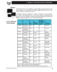
EZ Multiplexer
Hardware Manual
Manual Part Number EZ-MULTIDROP-M
WARNING!
Programmable control devices, such as Multiplexers, must not be used as stand-alone protection
in any application. Unless proper safeguards are used, unwanted start-ups could result in equipment damage or personal injury. The operator must be made aware of this hazard and appropriate
precautions must be taken.
In addition, consideration must be given to the use of an emergency stop function that is independent of the programmable controller.
The diagrams and examples in this user manual are included for illustrative purposes only. The
manufacturer cannot assume responsibility or liability for actual use based on the diagrams and
examples.
Trademarks
This publication may contain references to products produced and/or offered by other companies.
The product and company names may be trademarked and are the sole property of their respective
owners. AVG disclaims any proprietary interest in the marks and names of others.
Manual P/N EZ-MULTIDROP-M, Revision 1
© Copyright 2002–2003, AVG Automation
All Rights Reserved
No part of this manual shall be copied, reproduced, or transmitted in any way without the prior
written consent of AVG Automation. AVG Automation retains the exclusive rights to all information
included in this document.
MANUFACTURED by AVG AUTOMATION
4140 Utica Ridge Rd. • Bettendorf, IA 52722-1327
MARKETED by AUTOMATIONDIRECT.COM
3505 Hutchinson Road • Cumming, GA 30040
Phone: 1-770-844-4200 or 1-770-889-2858 • Fax: 1-770-889-7876 • www.Automationdirect.com
MAN-EZMUX-001, Revision 1 02/2003
TABLE OF CONTENTS
WARNING/Caution .................................................................. inside cover
Table of Contents ........................................................................................ i
Manual Revisions ...................................................................................... ii
INTRODUCTION
Introduction to the EZ Multilplexer ........................................................ 1
Multi-Panel System Diagram ............................................................... 2
What you need to get started ............................................................... 3
Hardware ........................................................................................ 3
Software ......................................................................................... 3
Need Help? ......................................................................................... 3
Onscreen HELP ............................................................................. 3
PLC HELP ...................................................................................... 3
Technical Support .......................................................................... 4
HARDWARE
Connections, Switches, LEDs and Outline Dimensions ................... 5
Outline Dimensions — Front View ................................................ 5
Outline Dimensions — Rear View ................................................ 6
EMI Noise Filter Installation ........................................................... 7
PLCs Supported by EZ Multiplexer ................................................ 8
Specifications ................................................................................. 9
Front Panel Features ................................................................... 10
Power Terminal ...................................................................... 11
PLC or Programming (Computer) Port: PLC/PROG ............ 11
EZText Panel Ports: COM1, COM2, COM3,
COM4, and COM5 .............................................................. 12
ERROR LED .......................................................................... 12
POWER LED .......................................................................... 13
Mode Switch ........................................................................... 13
PLC Terminator Resistor Switch ........................................... 13
MAINTENANCE
Fuse Reset ................................................................................... 14
TROUBLESHOOTING
Troubleshooting ........................................................................... 15
i
MANUAL REVISIONS
Manual Revisions
Manual Part Number: EZ-MULTIDROP-M
Manual Title: EZ Multiplexer Hardware Manual
The following table provides you with update information. If you call technical support with a
question about this manual, please be aware of the revision number.
Revision
Date
Effective Pages
Description of Changes
Original
Release
09/2002
Cover
Warning/Copyright
i–ii
1–16
Original Release of Manual
Revision 1
02/2003
Pages i and 7
Revision 1 adds EMI Noise Filter
Installation Instructions
ii
INTRODUCTION
Introduction to the EZ Multiplexer
The EZ Multiplexer is a communication master unit and was designed to allow
up to 5 EZText Panels to communicate with a single PLC. You may connect 5
of any combination of EZText Panels, including the EZ-SP Set Point Panel.
You will program each panel separately in your EZText Programming Software,
Version 2.0, Multi-Panel System project. After you select Multi-Panel System
in the programming software, you will select an EZText Panel — connected to
Port 1, Port 2, Port 3, Port 4, or Port 5 — and configure it individually. Each
EZText Panel in a Multi-Panel System may have a unique configuration. Only
the PLC settings are common to all five panels. When creating a MultiPanel Project, you can import a panel configuration from an existing project
file — or export it to another project file.
It is important to note that the EZ Multiplexer will only read and write to PLC
registers that the panels are currently monitoring. This significantly increases
the speed and performance of a Multi-Panel System.
The same port (PLC/Programming Port) is used for connection to either the
PLC or a programming computer. A MODE switch on the front of the unit (see
figure on page 10) allows you to select PROGRAM (setup) Mode or
MULTIPLEXER (run) Mode. You will use PROGRAM Mode (MODE switch is
ON) when Programming (connected to a computer) and MULTIPLEXER Mode
(MODE switch is OFF) when connected to a PLC. You will use cable P/N
EZTEXT-PGMCBL to connect the Multiplexer to a programming computer.
Above the PLC/PROG port are two LEDs that indicate communication between
the Multiplexer and PLC or between the Multiplexer and a programming
computer.
There are 5 panel ports used to connect to any of the EZText Panel models.
Above each EZText Panel port (COM1, COM2, COM3, COM4, and COM5) are
two LEDs that indicate communication between the Multiplexer and the EZText
Panels.
The PLC Attribute settings are the same for each Panel. The baud rate to each
of the panels is fixed. The Multiplexer supports the same PLCs as the EZText
Panel. All of the EZText Panels in a project are configured to use the same
PLC driver to communicate with the Multiplexer, this is done automatically by
EZText Programming Software, Version 2.0. Version 2.0 of the software will
support downloading the PLC driver, retrieving information from the Multiplexer
(revision and PLC attributes), and setting the PLC Attributes. For information
about Multi-Panel configuration, see the EZText Programming Software Getting
Started Manual, Version 2.0 that ships with the software CD, P/N EZ-TEXTEDIT.
EZ-MULTIDROP-M Revision 1
1
INTRODUCTION
An EZText Panel will request (read) the values of the PLC Addresses stored in
the EZ Multiplexer and will write new values to the EZ Multiplexer. The EZ
Multiplexer will constantly monitor the PLCs for all of the active stored
(programmed) addresses. By doing so, the EZ Multiplexer will always have
updated information for an EZText Panel request. Please note that the more
PLC register addresses that are active, the slower the update time will be.
Multi-Panel System Diagram
2
EZ-MULTIDROP-M Revision 1
INTRODUCTION
What you need to get started
Hardware
•
•
•
•
•
•
•
•
1 EZ Multiplexer, P/N EZ-MULTIDROP, master communication unit
1–5 EZText Panels (choose from models EZ-220, EZ-220L, EZ-420,
EZ-220P, EZ-SP)
24 Volt DC Power Supply (FA-24PS recommended)
RS-232C Programming Cable (P/N EZTEXT-PGMCBL) and set
MODE switch to ON to select Program (setup) Mode.
RS-422A Multiplexer to EZText Panel Cable—Belden 9729 or
equivalent, one per panel
RS-232C or RS-422A/485A PLC Cable (see page 10 for part
numbers)
Programmable Logic Controller (PLC)
PC requirements:
— IBM or compatible PC (486 or better) with a mouse
and separate serial port
— VGA display with at least 800 x 600 resolution (1024 x 768
recommended)
— Standard Windows 95/98 (Second Edition)/NT4.0/2000®
requirements
— CD ROM Drive
Software
•
EZText Programming Software (P/N EZ-TEXTEDIT, Version 2.0)
Need HELP?
PLEASE NOTE: The section on Troubleshooting at the end of this
manual should help you with most problems you might encounter.
Onscreen HELP
One of the most important features of the EZText Panel Programming Software
is the availability of context sensitive onscreen help. To access the Help
windows, simply press the F1 function key while on the topic where you need
help. For example, if you need help while working with panel configuration, hit
the F1 function key when that dialog box is open and a pop-up HELP window
will be displayed.
PLC HELP
If you need help with the PLC to EZText Panel Interface, consult the EZText
Panel Programming Software Help. Each PLC Driver has a Help Topic that
lists the error messages and provides an explanation for each. Also provided
are PLC to EZText Panel wiring diagrams.
EZ-MULTIDROP-M Revision 1
3
INTRODUCTION
Technical Support
Although most questions can be answered with EZText Programming Software
Version 2.0 HELP or the manuals, if you are still having difficulty with a particular
aspect of installation or system design, technical support is available at 1-770844-4200, Monday through Friday, 9 a.m. to 6 p.m. EST, or FAX us at 1-770886-3199. Visit our website at www.Automationdirect.com.
4
EZ-MULTIDROP-M Revision 1
HARDWARE
Connections, Switches, LEDs and Outline Dimensions
Outline Dimensions — Front View
All dimensions are provided in inches and millimeters ( mm are in [ ] ). See the
following page for side view and depth dimensions.
EZ-MULTIDROP-M Revision 1
5
HARDWARE
Outline Dimensions — Side View
All dimensions are provided in inches and millimeters (mm are in [ ] ).
6
EZ-MULTIDROP-M Revision 1
HARDWARE
EMI Noise Filter Installation
EZText Panels and the EZ Multiplexer are supplied with two ferrite cores that
should be attached to the cables prior to installation of the EZText Panel. These
cores are required to suppress EMI emissions that are conducted through the
Power Cable and the Communications Cable. The figure, below, shows the
ferrite cores properly installed. Attach the cores within one inch of the EZText
connector. The cable should be snugly wrapped once around the core,
providing two passes through the core.
The Power Cable Core is a solid ferrite cylinder. The Power Cable should
pass once through the core, be looped around and pass through a second
time. Pull the excess cable so that it rests snugly against the outside of the
core.
The Communications Cable Core is a snap-together, split, ferrite core. This
core can be installed on a finished cable. Lift the latch to open the core. Wrap
the wire through the core center, snugly around the outside, and again through
the center. Close the core until the latch snaps. Ensure that the cable jacket is
not pinched between the two halves of the core. The finished cable should
look similar to the drawing shown below.
Communications Cable
Power Cable
Lift up on latch
to open core
EZ-MULTIDROP-M Revision 1
7
HARDWARE
PLCs Supported by EZ Multiplexer
Below is a list of various PLCs and their protocols supported by the EZ
Multiplexer and by EZText Panels. Please note that we continue to add new
drivers to this list. If you don’t see your PLC listed here, please contact
Automationdirect.com or visit our web site.
PLC Brand
Allen-Bradley
Model
Micrologix 1000, 1200 and 1500
SLC5/03, /04, /05 (with DF1)
DF1 Half Duplex; DF1 Full Duplex
P LC 5
D F1
90/30 and 90/70
SNPX
Mitsubishi
FX Series (all)
Direct
Modicon
984 CPU, Quantum 113 CPU
AEG Modicon Micro Series 110 CPU:
311-xx, 411-xx, 512-xx, 612-xx
Modbus RTU
General Electric
Omron
DirectLogic
C 200, C 500
Host Link
D L05, D L06
K-Sequence; DirectNet;
ModBus (Koyo addressing)
D L105
K-Sequence
D2-230
K-Sequence
D2-240
K-Sequence; DirectNet
D2-250/D2-250-1/260
K-Sequence; DirectNet;
ModBus (Koyo addressing)
D2-240/250 DCM
DirectNet
D3-330/330P
DirectNet
D3-340
DirectNet
D3-350
K-Sequence; DirectNet;
ModBus (Koyo addressing)
D3-350 DCM
DirectNet
D4-430
K-Sequence; DirectNet
D L205
D L305
D4-440
K-Sequence; DirectNet
D4-450
K-Sequence; DirectNet;
ModBus (Koyo addressing)
D L405
All with DCM
8
Protocols Supported
DirectNet
Siemens
Siemens 7 MPI Adapter
3964R
Other
H2- WinPLC (Think-N-Do V5.2, check
for version compatability)
Modbus RTU (serial port)
EZ-MULTIDROP-M Revision 1
HARDWARE
Specifications
Power Supply:
20–30 VDC <2.5 Watts
Operating Temperature:
0 to 60 °C
Storage Temperature:
–20 to +70 °C
Humidity:
0–95% R.H, noncondensing
LED Indicators:
1 Green Power LED: Illuminates when power is applied to
unit
1 Red Error LED: Illuminates when there is an error with PLC
when in Multiplexer (Run) Mode, or illuminates in Program
(Setup) Mode when there is an error with the internal EXEC
firmware.
6 Green Transmit Data: Illuminates when port is transmitting
data
6 Red Receive Data: Illuminates when port is receiving data
Ports:
1 PLC/Programming Port: 15-position female D-sub
connector to PLC or Programming Computer. Operates in RS232C, RS-422A, or RS-485A modes. Communicates at a fixed
Baud.
5 EZText Panel Ports: 9-position male D-sub connector to
any model EZText Panel. Operates in RS-422A mode.
Communicates at a fixed Baud.
Switches:
1 Mode Switch: Used to switch panel between Program
(Setup) Mode and Multiplexer (Run) Mode.
1 PLC Terminator Resistor: Should be turned ON if the
Multiplexer is the first or last node on the network. Set to ON,
the RS-422/RS-485 signal is terminated.
External Dimensions:
6.5" x 5.0" x 0.901" (165.097 x 126.995 x 22.885 mm); Depth
including connector 1.544" (39.210 mm)
Weight:
0.9 lbs.
EZ-MULTIDROP-M Revision 1
9
HARDWARE
Front Panel Features
PLC TERMINATOR
RESISTOR Switch
Set to ON when unit is
first or last node on
network — the RS-422/
RS-485 signal is
terminated. See page 13.
MODE Switch
Set to ON when
programming, and set
to OFF when
connected to a PLC.
See page 13.
ERROR LED
Illuminates in PROGRAM mode when
there is an error with the internal firmware
(EXEC). Illuminates in MULTIPLEXER
(run) Mode when there is a PLC error. See
page 12.
POWER LED
Illuminates when power is
applied to the EZ
Multiplexer. See page 13.
OR
Power Terminals
Connect (+) on the unit to the
(+) lead of your power source.
Connect (-) on the unit to the
(-) lead, and chassis GND (on
the unit) is connected to the
chassis ground of the cabinet.
See page 11.
PLC/PROG Port
15-position Male D-Sub Connector.
Connect programming PC to this
port using cable P/N EZTEXTPGMCBL or connect to PLC using
the PLC cable appropriate for your
type PLC. See PLC Cable table,
page 11.
COM1, COM2, COM3, COM4, and
COM5 Ports
Five 9-position Male D-Sub connectors. Connect up to 5 (any
model) EZText Panels using cable
as shown on page 12.
TXD and RXD LEDs
Twelve LEDs that illuminate to
show transmit and receive data activity for the port directly below. See
page 12.
10
EZ-MULTIDROP-M Revision 1
HARDWARE
Power Terminal
It is recommended you use a regulated
power source isolated from relays,
valves, etc. Connect (+) on the unit to
the (+) lead of your power source.
Connect (-) on the unit to the (-) lead,
and chassis GND (on the unit) is
connected to the chassis ground of the
cabinet.
Power Connector
(P4, Phoenix 3-pin Header, 0.2 cntr)
Pin #
Connection
1
+V
2
–V
24VDC (20–30 VDC)
3
C hassis Ground
PLC or Programming (Computer) Port: PLC/PROG
There is one 15-position female D-Sub Connector, operating in RS-232C, RS422A, or RS-485A modes, at a fixed Baud Rate. This port (PLC/Programming)
is used for connection to either a PLC or a programming computer. A switch
on the front of the unit (see MODE Switch, below) allows you to select Program
(setup) Mode or Multiplexer (run) Mode. You will use Program Mode when
programming (connected to a computer) and Multiplexer Mode when connected
to a PLC. You will use one of the PLC cables listed in the table below to
connect to your type PLC. For programming, use cable P/N EZTEXT-PGMCBL.
PLC/PROG Port LEDs: TXD and RXD
PLC Cable Part Numbers
Part Number
Cable Description
EZ-2CBL
Direct Logic PLC RJ12 port, DL05, DL105, DL205,
DL350 & DL450 (RS-232C)
EZ-2CBL-1
Direct Logic (VGA Style) 15-pin port, DL250 (RS-232C)
EZ-3CBL
Direct Logic PLC RJ11 port, DL340 (RS-232C)
EZ-4CBL-1
Direct Logic PLC 15-Pin Dsub port, DL405 (RS-232C)
EZ-4CBL-2
Direct Logic PLC 25-Pin Dsub port, DL405, DL350,
DL305 DCU, and all DCM's (RS-232C)
EZ-90-30-CBL
GE 90/30 and 90/70 15-pin Dsub port (RS-422A)
EZ-SLC-232-CBL
AB SLC 5/03/04/05 DF1 port (RS-232C)
EZPLC5-232-CBL
AB PLC5 DF1 port (RS-232C)
EZ-DH485-CBL
AB SLC DH485 port (RS-485A)
EZ-MLOGIX-CBL
AB MicroLogix 1000, 1200 & 1500 (RS-232C)
EZ-MITSU-CBL
Mitsubishi FX Series 25-pin port (RS-422A)
EZ-MITSU-CBL-1
Mitsubishi FX Series 25-pin MINI-DIN (RS-422A)
EZ-OMRON-CBL
Omron C200, C500 (RS-232C)
EZ-S7MPI-CBL
Siemens 7 MPI Adapter (RS-232C)
EZ-MULTIDROP-M Revision 1
11
HARDWARE
Above the PLC/PROG port are two LEDs that
indicate communication between the
Multiplexer and PLC or between the Multiplexer
and a programming computer.
1 TXD (Transmit) Green LED - when
illuminated indicates that the port is
sending data
1 RXD (Receive) Red LED - when
illuminated indicates that the port is
receiving data
EZText Panel Ports: COM1, COM2, COM3, COM4, and COM5
There are five 9-position male D-Sub Connectors, operating in RS-422A mode,
at a fixed Baud Rate. These ports are used for connection for up to five of any
EZText Panel including the Set Point Panel (EZ-220, EZ-220L, EZ-420, EZ220P, EZ-SP). Use Belden 9729 or equivalent (one per panel) to connect panels
to COM ports. A wiring diagram for the cable is shown below.
COM1, COM2, COM3, COM4 and COM5 Port LEDs: TXD and RXD
Above each EZText Panel port (COM1, COM2, COM3, COM4, and COM5) are
two LEDs that indicate communication between the PLC and the EZText Panels:
5 TXD (Transmit) Green LED - when illuminated
indicates that the port is sending data
5 RXD (Receive) Red LED - when illuminated indicates
that the port is receiving data
ERROR LED
The ERROR LED indicates an error with the PLC when in Multiplexer (run)
Mode, or it indicates an error with the Multiplexer's internal firmware (EXEC)
when in Program (setup) Mode. It also flashes when switching between modes.
• When the EZ Multiplexer enters the Multiplexer Mode the ERROR
LED will blink on for 100 Msec and off for 100 Msec 5 times.
12
EZ-MULTIDROP-M Revision 1
HARDWARE
•
•
•
When the EZ Multiplexer enters the Program Mode the ERROR
LED will blink on for 400 Msec and off for 100 Msec 2 times.
While the EZ Multiplexer is in Multiplexer Mode (Run Mode) the red
ERROR LED will illuminate to indicate an error with the PLC. The
ERROR LED will illuminate for 2 seconds and then turn off while the
PLC driver tries to communicate with the PLC again. If there was an
error with the PLC, the PLC message will be displayed on all of the
EZText Panels that are connected and communicating with the EZ
Multiplexer.
When the Multiplexer Panel is in Program Mode —either because
the EZText Programming Software is sending new firmware, or
because on power up the Boot found that there is an invalid
EXEC— the ERROR LED will blink on for 1 second and off for 200
Msec continuously. YOU MUST reload the firmware, ensuring you
have the correct firmware.hex file.
POWER LED
The Power LED illuminates when power is applied to the unit.
Mode Switch
This switch allows you to switch the EZ Multiplexer between Programming
(setup) Mode and Multiplexer (run) Mode.
PLC Terminator Resistor Switch
Used to switch the RS-422/RS-485 termination resistor, ON or OFF. If the EZ
Multiplexer is the first or last node on the network, set the switch to ON to
prevent signal distortion. Set to ON, the RS-422/RS-485 signal is terminated.
EZ-MULTIDROP-M Revision 1
13
MAINTENANCE
Maintenance
Fuse Reset
The EZ Multiplexer features an AUTO-RESET fuse (0.65 Amp polyfuse). It is
reset by removing power for 5 minutes and then reapplying power to the unit.
14
EZ-MULTIDROP-M Revision 1
TROUBLESHOOTING
Troubleshooting
In this section we will explain how to isolate potential problems. If you cannot
isolate and remedy the problem using the procedures we have outlined below,
call technical support. For a list of EZText Panel, EZText Programming Software,
and PLC Driver Error Messages, see Appendix C in your EZText Panel User
Manual.
Problem: Multiplexer doesn’t have power.
1. Check the green Power LED on the front of the panel. It will illuminate
when power is applied to the unit. If it is not illuminated, check to
make sure power is applied to the unit.
2. Check power supply or replace.
3 . Ensure that the power terminal connections on the front panel of the
multiplexer are wired correctly.
Problem: Multiplexer is not communicating with programming computer.
1. Ensure that the MODE Switch on the front panel of the multiplexer is
set to PROGRAM (ON).
2. Check cable, ensure that it is the correct cable and that it is properly
connected at both ends.
3. Check multiplexer for power.
4. Check to ensure the correct PC COM port is selected in the EZText
Programming Software and that it is available in the PC.
5 Check to ensure that EZText Panels are in SETUP Mode. Press the
UP Arrow Pushbutton and hold while simultaneously pressing the
DOWN Arrow Pushbutton. The panels MUST be in setup mode to
communicate with the programming computer through the Multiplexer.
6. Check the COM1 setting in Setup Mode on the EZText Panel.
Problem: Multiplexer is not communicating with PLC.
1. Ensure that the MODE switch on the front panel of the multiplexer is
set to MULTIPLEXER (OFF).
2. Check to ensure cable from PLC to Multiplexer is the right cable, and
connected properly.
3. If Multiplexer is the first or last node on a network, check to make sure
that the PLC TERMINATOR RESISTOR switch on the front panel of
the multiplexer is set to TERMINATED (ON).
4. Check PLC settings:
a. Is PLC system powered?
b. Is PLC COM Port properly configured?
c. If there is a RUN switch on PLC, is it in the term/remote mode?
EZ-MULTIDROP-M Revision 1
15
TROUBLESHOOTING
Problem: Multiplexer is not communicating with one or more EZText
Panels.
1.
2.
Check to ensure that cable from Multiplexer to EZText Panel is the
correct cable (see page 11) and connected properly.
Check to ensure that the MODE switch is set properly. To program
the panels the MODE switch must be ON — in the PROGRAM Mode.
To run the panels the MODE switch must be OFF — in the
MULTIPLEXER Mode.
Problem: ERROR LED is illuminated.
The ERROR LED indicates an error with the PLC when in Multiplexer (run)
Mode, or it indicates an error with the Multiplexer's internal firmware (EXEC)
when in Program (setup) Mode. It also flashes when switching between modes.
•
When the EZ Multiplexer enters the Multiplexer Mode the ERROR
LED will blink on for 100 Msec and off for 100 Msec 5 times. This is
normal.
•
When the EZ Multiplexer enters the Program Mode the ERROR
LED will blink on for 400 Msec and off for 100 Msec 2 times. This is
normal.
•
While the EZ Multiplexer is in Multiplexer Mode (Run Mode) the red
ERROR LED will illuminate to indicate an error with the PLC. The
ERROR LED will illuminate for 2 seconds and then turn off while the
PLC driver tries to communicate with the PLC again. If there was an
error with the PLC, the PLC message will be displayed on all of the
EZText Panels that are connected and communicating with the EZ
Multiplexer. See Problem: Multiplexer is not communicating
with PLC.
•
When the Multiplexer Panel is in Program Mode— either because
the EZText Programming Software is sending new firmware, or
because on power up the Boot found that there is an invalid EXEC
— the ERROR LED will blink on for 1 second and off for 200 Msec
continuously. YOU MUST reload the firmware, ensuring you have
the correct firmware.hex file. See section on installation of new
firmware, this manual.
16
EZ-MULTIDROP-M Revision 1
TROUBLESHOOTING
Still need Help?
Check the EZText Panel User Manuals and/or EZText Programming Software
Manual/Help Topics for additional troubleshooting information. You also have
two additional sources for more information other than this manual.
Visit our web site at www.automationdirect.com
Our web site contains all of this information, any new feature releases, technical
support, plus much more...
Call our Technical Support Group Monday–Friday at 1-770-844-4200 or FAX
us at 1-770-886-3199.
If you have any questions that you can’t find an answer to, give us a call from
9 a.m. to 6 p.m. EST at the number above and we will be glad to assist you.
EZ-MULTIDROP-M Revision 1
17
This page intentionally left blank.
18
EZ-MULTIDROP-M Revision 1