1
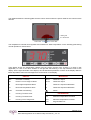
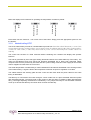
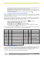
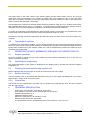
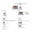
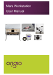
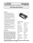
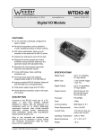
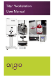
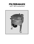
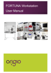
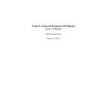
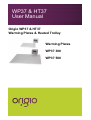
WP37 & HT37
User Manual
Origio WP37 & HT37
Warming Plates & Heated Trolley
Warming Plates
WP37 300
WP37 500
Heated Trolley
HT37
Origio WP37
Component Description
Heated work surface
Power supply and temperature controller
Model WP37 300
Model WP37 500
Origio HT37
Component Description
Page 2 of 13
WP37 Warming Plate & HT37 Heated Trolley User Manual _ Ver. 2.0
Heated work surface
Temperature controller
Controls for height adjustment
Side shelf
Three integrated power sources
Four lockable wheels
Temperature controller
Component Description
Actual temperature
DISPLAY
OFF
Controller in standby
OR
Probe T1 out of range or failure
HI
Room high temperature alarm
LO
Room low temperature alarm
TUN Controller in autotuning
E1
In tuning: Timeout1 error
E2
In tuning: Timeout2 error
E3
In tuning: Out of range error
INDICATION
OUT1 Channel 1 output
OUT2 Channel 2 output
L1
Channel 1 setpoint modification
L2
Channel 2 setpoint modification
Alarm
INFORMATION
THI
Maximum temperature recorded
TLO
Minimum temperature recorded
LOC Keypad state lock
Page 3 of 13
WP37 Warming Plate & HT37 Heated Trolley User Manual _ Ver. 2.0
TABLE OF CONTENTS
1
2
2.1
2.2
3
3.1
3.1.1
3.1.2
3.2
3.2.1
3.2.2
3.3
3.4
3.4.1
3.4.2
3.4.3
3.4.4
3.4.5
4
4.1
4.1.1
4.1.2
4.1.3
4.1.4
4.1.5
4.2
4.2.1
4.2.2
4.2.3
4.2.4
4.3
4.4
4.5
5
5.1
5.2
5.3
5.3.1
5.3.2
6
GENERAL INFORMATION ............................................................................................................... 5
IMPORTANT INFORMATION ........................................................................................................... 5
Safety Information .............................................................................................................................. 5
Operational Characteristics ................................................................................................................ 5
PRODUCT OVERVIEW ..................................................................................................................... 5
Product Hardware Description ........................................................................................................... 5
Warming plates WP37........................................................................................................................ 5
Heated trolley HT37 ........................................................................................................................... 7
Product Operation description ............................................................................................................ 9
WP37 warming plates ........................................................................................................................ 9
HT37 heated trolley ............................................................................................................................ 9
Product Performance Description ...................................................................................................... 9
The parameters 1PB, 1IT, 1DT, 1AR and 1CT ................................................................................ 10
Proportional bandwidth (1PB) .......................................................................................................... 10
Integral action time (1IT) .................................................................................................................. 10
Derivative action time (1DT) ............................................................................................................. 10
Reset of integral action time referred to 1PB (1AR)......................................................................... 10
Cycle time (1CT) .............................................................................................................................. 10
USER SETUP .................................................................................................................................. 10
Accessing the parameters ................................................................................................................ 10
Accessing the information menu ...................................................................................................... 10
Reset the THI and TLO recordings .................................................................................................. 11
Channel 1 setpoint ........................................................................................................................... 11
Standby ............................................................................................................................................ 11
Keypad lock ...................................................................................................................................... 11
Controller autotuning in PID mode ................................................................................................... 11
Before starting .................................................................................................................................. 11
Start autotuning ................................................................................................................................ 11
During autotuning ............................................................................................................................. 11
Errors ................................................................................................................................................ 11
Accessing the factory set operating parameters .............................................................................. 12
Determining the offset ...................................................................................................................... 12
Temperature variation ...................................................................................................................... 13
OPERATING THE WP37 WARMING PLATES AND HT37 HEATED TROLLEY .......................... 13
Normal operation .............................................................................................................................. 13
Checking the temperature ................................................................................................................ 13
Cleaning the work surface and control unit ...................................................................................... 13
Surface cleaning............................................................................................................................... 13
Control box ....................................................................................................................................... 13
TECHNICAL SPECIFICATION ........................................................................................................ 13
Page 4 of 13
WP37 Warming Plate & HT37 Heated Trolley User Manual _ Ver. 2.0
1
GENERAL INFORMATION
This manual contains information that is subject to copyright. All rights reserved. This manual should not be
photocopied, otherwise copied or distributed, completely or in part, without the approval of ORIGIO ScanLab
Equipment A/S.
There are no user serviceable parts in either the controller or warming plate or the trolley and any service
problems must be referred to Origio ScanLab Equipment.
The units are designed to be powered from a mains electricity supply (check rear of unit for operating
voltage) and it must be earthed via the incoming mains lead.
2
IMPORTANT INFORMATION
2.1
Safety Information
Before use the warming plates must be placed on a level and reasonably heat resistant surface.
Before use the heated trolley must be placed on a level surface preferably with little to no traffic around it and
the castors should be locked. Be aware of the power cord for the trolley. Appropriate securing and marking
of the power cord must be assured for personnel safety.
2.2
Operational Characteristics
The warming plates and the top working surface on the heated trolley (they are essentially identical units) will
warm to 37 ºC and is controlled by an accurate sensor and control processor.
Placing of large hot or cold masses on the heated elements will affect the regulation process and should be
avoided during normal operation.
Placing a hand will also draw heat from the surface therefore please avoid placing fingers or a hand on the
surface during warming up or during calibration of the controller.
Turn on the heating system at least 30 minutes before starting the work. If possible place all needed
equipment on the surface during the warming up period to warm these appropriately. Always wait for the
temperature to stabilize completely before starting work.
3
PRODUCT OVERVIEW
3.1
Product Hardware Description
3.1.1
Warming plates WP37
The WP37 System consists of a separate control unit, a power cord for said unit, the heated plate module
made from heated anodised aluminium and interconnecting cable between the heated plate and the control
unit.
The control unit consists of a free standing cabinet containing the controller with display and operator
interface.
The heat is generated by one (WP37 300) or two (WP37 500) mat type heating elements build into the
warming plate. The mats are self-adhesive and have etched foil elements embedded into a glass cloth
supported rubber compound. Each mat is powered by 230 VAC and has a power rating of 100 W. Power
supply for the heated mats is supplied via cable from the control unit.
The actual temperature is measured by a class B standard PT100 element embedded in the warming plate.
A signal is feed to the temperature controller as input for regulation via a cable.
Page 5 of 13
WP37 Warming Plate & HT37 Heated Trolley User Manual _ Ver. 2.0
The cables between the warming plate and the control unit as well as the power cable for the control unit are
all fixed.
Heating mat
PT 100 element
PT100 cable
Power cable
The temperature controller that regulates and maintains a stable temperature on the warming plate during
normal operation is shown below.
Thee display shows the temperature readout from the chosen channel (only channel 1 is used on this
application). In case of an alarm situation a red light will start flashing in the top left-hand corner of the
display. On the right-hand side of the display it is indicated which parameter is shown in the display. Below is
listed all possible values and messages that can be shown in the display:
DISPLAY
INDICATION
OFF
Controller in standby
OUT1
Channel 1 output
OR
Probe T1 out of range or failure
OUT2
Channel 2 output
HI
Room high temperature alarm
L1
Channel 1 setpoint modification
LO
Room low temperature alarm
L2
Channel 2 setpoint modification
TUN
Controller in autotuning
E1
In tuning: Timeout1 error
E2
In tuning: Timeout2 error
THI
Maximum temperature recorded
E3
In tuning: Out of range error
TLO
Minimum temperature recorded
LOC
Keypad state lock
Alarm
INFORMATION
Page 6 of 13
WP37 Warming Plate & HT37 Heated Trolley User Manual _ Ver. 2.0
Standby
Exit
Modify setpoint 2
Increase value
Decrease value
Modify setpoint 1
Enter
Information
Below the display the four buttons for operating the temperature controller is placed:
Each button has two functions - one in each end of the button. Simply press the appropriate symbol to use
the buttons.
3.1.2
Heated trolley HT37
The HT37 heated trolley consists of a heated table top made from heated anodised aluminium, a control unit
mounted just below the working surface, a motorized column for adjusting the height of the working surface,
controls for said column, a side shelf, three build in power sources and finally four lockable castors for
mobility.
The control unit consists of a fixed mounted cabinet containing the controller with display and operator
interface.
The heat is generated by three mat type heating elements build into the heated table top of the trolley. The
mats are self-adhesive and have etched foil elements embedded into a glass cloth supported rubber
compound. Each mat is powered by 230 VAC and has a power rating of 267 W. Power supply for the heated
mats is supplied via cable from the control unit.
The actual temperature is measured by a class B standard PT100 element embedded in the working surface
of the heated trolley. A signal is feed to the temperature controller as input for regulation via a cable.
The cables between the warming plate and the control unit are fixed while the power cable for the entire
trolley is detachable.
The table top is connected to the base through a column made from a 2-piece anodized aluminium profile
with integrated actuator. The travel length of the column is 300 mm and it is capable of lifting approximately
50 kg. The height adjusting mechanism is controlled by a very simple and easy to use two-button interface:
Arrow-up to elevate the table top and arrow-down to lower the table top.
Page 7 of 13
WP37 Warming Plate & HT37 Heated Trolley User Manual _ Ver. 2.0
850 mm
Side shelf
1250 mm
Controls for height
The side shelf mounted under the table top is designed as an easy way to store equipment used during the
work processes without taking up space on the table top.
The three build-in power sources are protected by lids, when not in use. They are rated IP44.
For mobility the trolley is equipped with four easy-rolling castors. Fore safety during work the castors are all
equipped with brakes to ensure that the trolley is stationary during use. Always remember to engage the
brakes before starting work.
The temperature controller that regulates and maintains a stable temperature on the warming plate during
normal operation is shown below.
Thee display shows the temperature readout from the chosen channel (only channel 1 is used on this
application). In case of an alarm situation a red light will start flashing in the top left-hand corner of the
display. On the right-hand side of the display it is indicated which parameter is shown in the display. Below is
listed all possible values and messages that can be shown in the display:
DISPLAY
INDICATION
OFF
Controller in standby
OUT1
Channel 1 output
OR
Probe T1 out of range or failure
OUT2
Channel 2 output
HI
Room high temperature alarm
L1
Channel 1 setpoint modification
LO
Room low temperature alarm
L2
Channel 2 setpoint modification
TUN
Controller in autotuning
Alarm
Page 8 of 13
WP37 Warming Plate & HT37 Heated Trolley User Manual _ Ver. 2.0
INFORMATION
E1
In tuning: Timeout1 error
E2
In tuning: Timeout2 error
THI
Maximum temperature recorded
E3
In tuning: Out of range error
TLO
Minimum temperature recorded
LOC
Keypad state lock
Standby
Exit
Modify setpoint 2
Increase value
Decrease value
Modify setpoint 1
Enter
Information
Below the display the four buttons for operating the temperature controller is placed:
Each button has two functions - one in each end of the button. Simply press the appropriate symbol to use
the buttons.
3.2
Product Operation description
3.2.1
WP37 warming plates
On power up the temperature controller is turned on and the heating elements start warming up immediately.
The factory setpoint temperature is 37 °C.
If a different temperature is needed, the setpoint must be changed. For details, see below.
Before starting work the temperature of the warming plate must be stabilized. Warming up time will depend
on what equipment is placed on the warming plate during warm up.
The temperature is stabilized when the display shows the correct temperature (the setpoint temperature) and
stays within ± 0,1 °C of this. Calculate with at le ast 30 minutes to 1 hour to be sure. Make sure that it is the
value for OUT1 that is displayed.
3.2.2
HT37 heated trolley
The same description as above applies.
The height adjustment system is ready for use as soon as the power is turned on.
3.3
Product Performance Description
The warming plates WP37 300 and WP37 500 and the heated trolley HT37 are all designed to provide and
maintain a constant 37 °C over the heated part of t he working surfaces to within ± 0,2 °C at a maximum
ambient temperature of 36 °C.
The controller is operating in PID (Proportional-Integral-Derivative) mode to get the most accurate and stable
temperature possible. When running in PID mode the parameters 1PB, 1IT, 1DT, 1AR, 1CT will be used.
Page 9 of 13
WP37 Warming Plate & HT37 Heated Trolley User Manual _ Ver. 2.0
3.4
The parameters 1PB, 1IT, 1DT, 1AR and 1CT
3.4.1
Proportional bandwidth (1PB)
Temperature control takes place by changing the ON time of the output:
the closer the temperature to the setpoint, the less time of activation. A
small proportional band increases the promptness of response of the
system to temperature variations, but tends to make it less stable. A
purely proportional control stabilises the temperature within the
proportional band but does not cancel the deviation from setpoint.
The value of this parameter must be verified by an “autotuning”. See
below.
3.4.2
Integral action time (1IT)
The steady-state error is cancelled by inserting an integral action. The
integral action time, determines the speed with which the steady-state
temperature is achieved, but a high speed (1IT low) may be the cause of
overshoot and instability in the response.
The value of this parameter must be verified by an “autotuning”. See
below.
3.4.3
Derivative action time (1DT)
Response overshoot may be reduced by inserting a derivative Action. A
high derivative action (1DT high) makes the system very sensitive to
small temperature variations and causes instability.
The value of this parameter must be verified by an “autotuning”. See
below.
3.4.4
Reset of integral action time referred to 1PB (1AR)
Decreasing the parameter 1AR reduces the integral control action zone, and consequently the overshoot
(see figure in paragraph 1IT).
The value of this parameter must be verified by an “autotuning”. See below.
3.4.5
Cycle time (1CT)
It’s the period in which the output ON time changes. The quicker the system to be controlled reacts to
temperature variations, the smaller the cycle time must be, in order to obtain higher temperature stability and
less sensitivity to load variations.
4
USER SETUP
Generally the units are delivered ready for use from the factory. Should it be necessary to access the
parameters in the temperature controller, this is how it is done:
4.1
Accessing the parameters
4.1.1
Accessing the information menu
o
Press and immediately release button .
Page 10 of 13
WP37 Warming Plate & HT37 Heated Trolley User Manual _ Ver. 2.0
o
o
o
With button
or
select the data to be displayed.
Press button to display value.
To exit from the menu, press button or wait for 10 seconds.
4.1.2
Reset the THI and TLO recordings
o
o
o
With button
or
select the data to be reset.
Display the value with button .
While keeping button pressed, use button .
4.1.3
Channel 1 setpoint
o
o
o
Press and release button : the LED L1 blinks, the display shows 1SP for 1 second and then the
setpoint associated value.
Press buttons
or
to set the desired value (adjustment is within the minimum SPL and
maximum SPH limit).
To store the new value press button , or wait for 10 seconds.
To go back to normal mode without saving the new value, press .
4.1.4
Standby
o
Button , when pressed for 3 seconds, allows the controller to be put on a standby or output control to be
resumed (with SB=YES only).
4.1.5
Keypad lock
The keypad lock avoids undesired, potentially dangerous operations, which might be attempted when the
controllers is operating in a public place. In the INFO menu, set parameter LOC=YES to inhibit all functions
of the buttons. To resume normal operation of keypad, adjust setting so that LOC=NO.
4.2
Controller autotuning in PID mode
This operation should only be performed by a trained technician during service or re-calibration.
4.2.1
Before starting
In the setup mode (see configuration parameters): set 1CM=PID; make sure that 1CH matches the desired
operation mode (1CH=REF for refrigerating control, 1CH=HEA for heating control); then adjust setpoint 1SP
at the desired value.
4.2.2
Start autotuning
During normal operation, keep buttons +
pressed for 3 seconds. 1CT blinks on the display. With +
or
set the cycle time in order to define the dynamic of the process to be controlled. To abort the
autotuning function, press ; to start autotuning press
+
or wait for 30 seconds.
4.2.3
During autotuning
During the entire autotuning phase, the display alternates TUN with the actual temperature measured. In
case of power failure, when power is resumed, after the initial auto test phase, the controller resumes the
autotuning function. To abort the autotuning, without modifying the previous control parameters, keep button
pressed for 3 seconds. After the autotuning has taken place successfully, the controller updates the
control parameters and starts to control.
4.2.4
Errors
If the autotuning function failed, the display shows an error code:
o
E1 timeout1 error: the controller could not bring the temperature within the proportional band.
Increase 1SP in case of heating control, vice versa, decrease 1SP in case of refrigerating control
and re-start the process.
Page 11 of 13
WP37 Warming Plate & HT37 Heated Trolley User Manual _ Ver. 2.0
o
E2 timeout2 error: the autotuning has not ended within the maximum time allowed (1000 cycle
times). Re-start the autotuning process and set a longer cycle time 1CT.
E3 temperature out of range: check that the error was not caused by a probe malfunction, then
decrease 1SP in case of heating control, vice versa increase 1SP in case of refrigerating control
and then re-start the process.
To eliminate the error indication and return to the normal mode, press button .
4.3
Accessing the factory set operating parameters
o
o
Before the temperature controller can be used, a number of parameters must be set and the displayed
temperature calibrated. This is done at the factory before delivery. It is not advisable to change any of the
parameters mentioned in this paragraph.
Start the process by turning on the temperature controller and wait until the heated area on the work surface
has reached the set temperature – factory setting is 37 °C – and the temperature reading has stabilize d. To
enter the parameter configuration menu follow the procedure below:
To get access to the parameter configuration menu, press button + for 5 seconds.
With button
or
select the parameter to be modified.
Press to display the existing parameter value.
By keeping pressed, use button
or
to set the desired value.
When is released, the newly programmed value is stored and the next parameter is displayed.
To exit from the setup, press or wait for 30 seconds.
o
o
o
o
o
o
In the table below are listed all the parameters that are not the temperature controller manufacturers default
values. These parameters has been changed or set at the factory before delivery
Parameter
Value
SCL
Parameter
Value
1
1CT
1
SPL
0
1PF
OFF
SPH
50
OAU
NON
1SP
37
ATM
NON
1CM
PID
SB
YES
1CH
HEA
OS1
X,X
1PB
3,0
To be verified by an “autotuning”.
TLD
0,5
1IT
209
To be verified by an “autotuning”.
SIM
0,5
1DT
44
To be verified by an “autotuning”.
ADR
1
1AR
50
To be verified by an “autotuning”.
4.4
Remarks
Remarks
Calibration offset.
Determining the offset
OS1: This is the offset between the displayed temperature and the actual temperature on the work surface.
The value is calculated as the difference between the measured and the displayed temperature OS1 = TM TD (= 35,7 - 37,0 = -1,3). After entering the calculated offset make a check measurement of the accuracy of
the calibration. The difference between the displayed and measured should be within ± 0,1 °C.
To determine the value of TD the following procedure should be followed:
Page 12 of 13
WP37 Warming Plate & HT37 Heated Trolley User Manual _ Ver. 2.0
The heated zone on the work surface of the warming plates and the heated trolley are one, two or three
rectangular areas corresponding to the number of heated mats on the particular unit. As only one offset
value can be entered in controller, the average temperature measured centrally on each of the heated mat
areas is used for the calculation of the offset.
The temperature is measured in the appropriate measuring positions using type k (or equal) thermocouples
and a suitable thermometer with 0,1 °C resolution. The thermometer including the thermocouple(s) must be
calibrated, as the set point temperature calibration is an absolute temperature calibration.
To ensure good thermal contact between the thermocouple and the work surface, the exposed end of the
thermocouple must be fastened to the work surface using aluminium tape or equal.
Calculate the average measured temperature and from this value the value of OS1. Enter this value in the
controller.
4.5
Temperature variation
To determine the temperature variation over the heated surface use the method and equipment described
above. On each mat six evenly spread positions is measured and the difference between the highest and the
lowest value measured gives the variation. Make sure, that all measurement positions are within the area
covered by the heated mats.
5
OPERATING THE WP37 WARMING PLATES AND HT37 HEATED TROLLEY
5.1
Normal operation
Once the controller is setup correctly it will maintain the work surface temperature at 37 °C and will not
require any further interaction.
5.2
Checking the temperature
The actual temperature of the surface is displayed on the display (OUT1) and will also show the setpoint
temperature L1.
5.3
Cleaning the work surface and control unit
Before cleaning make sure the power is off and the cord removed from the supply.
5.3.1
Surface cleaning
The work surface must not be cleaned with abrasives of any kind. Use normal mild detergents or an alcohol
based cleaner. Always clean using a soft cloth.
5.3.2
Control box
The control box can cleaned with a soft cloth only, no liquids of any kind and only when the unit is isolated
from the mains supply.
6
TECHNICAL SPECIFICATION
o
o
o
o
o
o
o
Power Input, 220-240 VAC, 50-60 Hz via an IEC lead
Fuse protection, minimum 5A A/C (WP37) and 13A A/C (HT37)
Operating temperature 37 °C
Calibration Method, Offset
Warm up to quiescence = 30 minutes to 1 hour
Earthed chassis with 3 wire mains lead
The temperature accuracy (maintained by the PT100 sensor) is ± 0,2 °C at 37 °C
Page 13 of 13
WP37 Warming Plate & HT37 Heated Trolley User Manual _ Ver. 2.0