1
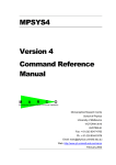
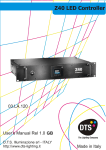
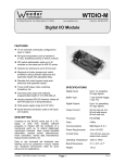
Messaging Software User Manual FOR PC OPERATIONS Notes: 5 August 2004 This manual is applied to the model(s) of LED Multi line Message Displays Note: Specifications are subject to change without notice Programming Manual MANAGEMENT SOFTWARE 1.1. Copy the Management Software from floppy disk (A:\) to hard disk (C:\). Double click it and run this program, you will see a dialog box as (Picture 1): (Picture 1) Set parameters of LED display: Color • Single color: it is a single color Display, it can present only red and black color. • Double colors: it is a double color Display, it can present red, green, yellow, and black. • Scale colors: it is a 256 scale colors Display. But it is still not available. Communication mode RS-232: using serial port to communicate with Display. RS-422: using ISA communication card to communicate with Display, however, it is still not available at this moment. Width the number of pixels in a row Height the number of pixels in a column Note that: For single color Display, it should not be more than 64 pixels. While for double color Display, it should not be more than 32 pixels. Number stored it shows the maximum number of screens that can be saved. Because the memory of Display is limited, this value depends on the width, height, and colors of the display. ¾ IMPORTANT NOTICE: Make sure that all the parameters are set up correctly. Otherwise, the display cannot work properly. - Page 2- Programming Manual 1.2. Menu After finishing setting up the parameters, click “Set”, you will enter into the main menu of the program. (Picture 2). 2.1 File (F) Æ. It includes 7 submenus as below: (i) Open (O) Use to open a created file, as a file format *.SDV. (ii) Clear (C) Use to clear the contents in editing area. (iii) Save (S) Use to save the contents in editing area, as a file format *.SDV. (iv) Save as (A) Use to save the contents in editing area with a new file name. (v) Import Import a graphic file, as a file format *.bmp file. (vi) Export Export a graphic file, as a file format *.bmp file from the editing area. (vii) Exit (E) Exit this program. - Page 3- Programming Manual 2.2 Edit (E) Æ. It includes 6 sub-menus as below. (i) Undo (U) Recall the latest command. (It is still not available.) (ii) Cut (T) Cut the selected content and copy it onto clipboard. (iii) Copy (C) Copy the selected content onto clipboard. (iv) Paste (P) Paste the content on clipboard into the editing area. Only two file formats can be identified by this program (*.txt and *.bmp). (v) Select all (A) Select all the contents in the editing area. (vi) Delete (Del) Delete the selected contents. 2. 3 Send (S) Æ (i) Send file Send the contents in editing area to Display and this should be done after finishing all the set-up. (ii) Set Moving Method Click “Set Moving Method”, you will see the “setting parameters” dialog box as (Picture 3), which gives user different options on display mode, speed, animation effects and styles of cartoon in each key frame of LED display. (Picture 3) - Page 4- Programming Manual a) Key It shows the total number of frames that will be displayed on screen. b) Import mode It gives user different types of importing display modes, by which the contents appear in the key frame at start. Refer to (Picture 4), this mode includes: (Picture 4) Move from left or right Scroll up or bottom Jump from right Open from left, right, up, bottom, center or both sides Cover from center or both sides Immedia Ready Random … c) Export mode Similarly, it can also give user different types of exporting display modes, by which the contents disappear in the key frame at last. (Picture 5) - Page 5- Programming Manual d) Speed It can control the moving speed of signal which displays on screen. Looking at (Picture 6), the level of speed can be from Slow Æ Median Æ Fast Æ Fastest. (Picture 6) e) Append mode In “Append mode”, see the dialog box as (Picture 7), this mode can provide different animation effects and styles of cartoon in each key frame of LED display: (Picture 7) Users can select one or more options of animation effects accordingly. Flicker the contents will flash three times continually after they appear in the Display. Pause the contents will pause for certain seconds after they appear in the Display. User can choose the pause time by inputting a data into above dialogue. Continuum the next key frame will appear immediately while the previous key frame disappears. Quiescence the contents will stop on the screen unless new contents are sent to it. It is suitable to display one page mode. - Page 6- Programming Manual Users can select one of the cartoon types accordingly. Cartoon type and Horse. these include Eat bean, Toxophily, Weight lifting, Lion f) SetCol Click ”SetCol” in Picture 3, the dialog box (Picture 8) will then be seen. The “Set col” option is mainly used to set import mode, export mode, speed or append mode with respect to the specified screen. (Picture 8) For example, if there is more than one screen that users want to set every screen’s export mode as the same as screen 3 one (see Picture 9a), i.e. Move from right, user only need to choose appropriate setting option in Picture 8, then all the export mode in other screen will be as same as the specified one (see Picture 9b). (Picture 9a) - Page 7- Programming Manual (Picture 9b) g) SetRow Click ”SetRow” in Picture 3, the dialog box (Picture 10) will then be seen. The “Set row” option is mainly used to perform the same settings of import mode, export mode, speed and append mode with respect to the specified screen. (Picture 10) For example, if there is more than one screen that user want to set every screen’s parameters as the same as screen 1 (see Picture 11a). User can only need to choose appropriate setting option in Picture 10, then all the parameters in other screen will be as same as the specified one (see Picture 11b). - Page 8- Programming Manual (Picture 11a) (Picture 11b) (iii) Adjust time When all the above parameters are set okay, click “Adjust time” in picture 2. will see the following dialog box (See Picture 12) Now you (Picture 12) • Communication Port (COM1/COM2) by which computer can communicates with Display. The default port is COM2. Users need to select the suitable port according to his practical need. If users select a port which are been using by mouse or other programs, the Manage Software will give a notice that “the selected port have been used, please choose others”. • Address of Moving-Sign the number of the Display, and the files will be sent. The default Display number is “0”, in such case; the sending files will be received by all the connected Displays. It is very useful when there are more than one Displays connected. - Page 9- Programming Manual ¾ IMPORTANT NOTICE: If the files need to be sent more than one Display but not all the connected Displays, please input their Display numbers accordingly and separate them with a comma. For example, if the No.1, No.3, No.5, No. 10 Displays accept the files, then input “1,3,5,10” into the blank box. Please note below: 1. the first and last character cannot be a comma. 2. two connected commas are invalid. 3. the Display numbers can not exceed 255. Check whether the communication line connected with computer’s COM port correctly or not. When these two parameters are ready to setup, click “OK”. Now, you will see the dialog box (See Picture 13) (Picture 13) By which, users can have three options to adjust on time display. • Horizontal position of timer display (BYTE as units). • Vertical position of the timer display (BYTE as units). • Display second. Note that: The standard time adjustment comes from the clock of computer. (iv) Open Multi-language Moving-Sign By which, this moving sign adjustment allows user to input the corresponding language of character rather than his own country. (v) Close Multi-language Moving-Sign By which, this moving sign adjustment does not allow user to input the corresponding language of character rather than his own country. (vi) Display Multi-language Moving-Sign’s address By which, the display’s number will be shown on the screen all the time, so that user can check this information conveniently. - Page 10- Programming Manual (vii) Close Multi-language Moving-Sign’s address If users don’t want the Display’s number to appear on the screen all the time, clicking this will then close it. (viii) Set Multi-language Moving-Sign’s address This function is still not available at this moment (ix) Timer It is used to set up some functions of timer. Click it, you will see the following dialog box. (See Picture 14) ① ② ③ ④ ⑤ ⑥ ⑦ ⑧ ⑨ (Picture 14) ① the number of timers set, total 8 timers. ② If it is selected, the timer will be closed. ③ If it is selected, the timer will be opened. ④ Set the starting date (from Mon~Sun). ⑤ ⑥ Set the starting time (including both hour & minute) ⑦ If it is selected, the timer’s time is the close time of the Display. ⑧⑨ Set the screen numbers of starting and ending. 2.4 View (V) Æ (i) Status bar (S) It can be hided or displayed. • • • The data in the 1st box is the coordinate of mouse (X,Y) located at specified areas. The data in the 2nd box is the drag size of mouse (CX,CY) located at specified areas. The data in the 3rd box is the screen number where the mouse locates. - Page 11- Programming Manual (ii) Grid (Ctrl + G) This function can be used only when the contents are magnified 6x or 8x times. • When users want to make an exact orientation by using “zoom” tool, click “Grid”, you can find an each small grid which is a pixel in the normal state. • If you want to hide it, click “Grid” again, the grid will disappear from the screen. (iii) Separate Line (Ctrl + L) This function is to hide or display the division line of each screen, so that users can identify the contents within an editing area of each screen, so that it can avoid the crossover between each other. (iv) Palette tool (Ctrl + P) Current foreground color • • • • • (v) Current background color It can be used to set the color of object. For single color Display, there are only two colors: red and black. For dual colors Display, there are four colors: red, black, green, yellow. The color selected by clicking the left key of mouse is for foreground color, while the color selected by clicking the right key of mouse is for background color. If users want to change the colors of previous pictures, select the subjected pictures first, and then choose the foreground color and background color respectively. Draw tool (Ctrl + D) • You can use “Pen” to draw a free line in the editing area as you like. Besides, you can use “Line” and “Arc” to draw a straight line and curve respectively. - Page 12- Programming Manual • When you select or , you will see the line width table as follows diagram: Note that: If you want to change the thickness of the finished line or arc, select the required line or arc; follow by choosing the thickness of line just you want. • If you want to edit some pixels exactly, you can click the “Zoom” status toolbox, and then choose the multiple magnifying scales just you want. • You can draw some of the following shapes in the editing area, including both: Rectangle Round Rectangle Oval Polyline • . You can insert text, click “ ”, you can see the following dialog box: - Page 13- Programming Manual (vi) • You can insert text in different formats, including both: Type of characters, i.e. text, symbol, number, etc Size (value from 0~80) Opaque / Transparent mode Style of characters, i.e. Bold, Italic, Underline Align Tool (Ctrl + T) The functions of tools: Align Left The selected object is aligned toward left. This button is valid only when two or above objects is selected. In such case, this will take the most left subject as a reference and all the others will be aligned toward left. Align Right The selected object is aligned toward right. This button is valid only when two or above objects is selected. In such case, this will take the most right subject as a reference and all the others will be aligned toward right. Align Top The selected object is aligned toward top. This button is valid only when two or above objects is selected. In such case, this will take the most top subject as a reference and all the others will be aligned toward top. Align Bottom The selected object is aligned toward bottom. This button is valid only when two or above objects is selected. In such case, this will take the most bottom subject as a reference and all the others will be aligned toward bottom. Center Vertical The selected object in the vertical middle. If the height of selected object exceeds the screen, this button will be invalid. Center Horizontal The selected object in the horizontal middle. If the width of selected object exceeds the screen, this button will be invalid. Space Across It makes the horizontal interval of selected objects in - Page 14- Programming Manual same space. That means the horizontal space between the first object and the second object is same as the space between the second object and third object. This button is valid only when three or more objects are selected. Space Down It makes the vertical interval of selected objects in same space. That means the vertical space between the first object and the second object is same as the space between the second object and third object. This button is valid only when three or more objects are selected. Make Same Width It makes all the selected objects have a same width. The button is valid only when two or more objects are selected. The last selected object will be taken as a reference, all the others have the same width with it. Make Same Height It makes all the selected objects have a same height. The button is valid only when two or more objects are selected. The last selected object will be taken as a reference, all the others have the same height with it. Make Same Size It makes all the selected objects have a same height and width. The button is valid only when two or more objects are selected. The last selected object will be taken as a reference, all the others have the same height and width with it. Specify Position It make all the selected objects as its specified position and size, i.e. starting horizontal point, starting vertical point, width and height. You will see following dialog box: - Page 15- Programming Manual 3. Operation on “Right Click” function of mouse 3.1. Converting data into BMP Picture If users want to convert the content of one screen into BMP picture, they should follow the below procedure: (i) Deselect any object by (Press “ESC” key) to cancel all the selections. (ii) Click the right key of the mouse on specified keyframe from the editing area, you will see a dialog box “ Convert this to BMP” and follow the step: (iii) Then there appears another dialog box inquiring about the filename. Input a file name as you want, all the objects in this screen will be changed into BMP file. 3.2. Invert axis After users import a BMP file from the file submenu, or copy a BMP file from clipboard, select this object, and click the right key of the mouse at the same time, you will see following menu: “invert X axis”: “invert Y axis”: flip the image around X axis flip the image around Y axis 3.3. Change row spacing If you select a text object, and click the right key of mouse at the same time, you will see “Change row spacing” dialog box Follows the step, another new dialog box will exist as below: - Page 16- Programming Manual • Select the “ A line of characters can span on one screen” box, the text can then be displayed in more than one screen, and users can move the text object into any screen. Deselect this box and then the text cannot be displayed in different screens. Note that: This program will make an adjustment automatically according to its current position. When users move the text, some part of the texts may not be seen because of the adjustment from the program. • Select the “Fix the row spacing” box, you can input a value into it. The value is the space between two neighbor lines (unit: pixels). It is workable for the whole file. • Deselect the “Fix the row spacing” box, you can input a value into “Row spacing of selecting” box. The value is also the space between two neighbor lines, but it is only workable for the selected text. • Click the “Set row spacing to default” box, the program will use the default line-space on the whole file. 4. Other functions 4.1. Table of key function Select any objects such as text, shape or line, and then press the following types of key that will operate each specified function: “←” “↑” “→” “↓” “Ctrl + →” “Ctrl+ ←” “Ctrl + ↑” “Ctrl+↓” “Shift + →” “Shift + ←” Move object towards left with one pixel Move object towards up with one pixel Move object towards right with one pixel Move object towards down with one pixel Modify object by moving its left sides of column towards right with one pixel, i.e. the width of object should be smaller Modify object by moving its left sides of column towards left with one pixel, i.e. the width of object should be bigger Modify object by moving its top of row towards up with one pixel, i.e. the height of object should be bigger Modify object by moving its top of row towards down with one pixel, i.e. the height of object should be smaller Modify object by moving its right sides of column towards right with one pixel, i.e. the width of object should be bigger Modify object by moving its right sides of column towards left with one pixel, i.e. the width of object should be smaller - Page 17- Programming Manual “Shift + ↑” “Shift +↓” Modify object by moving its bottom of row towards up with one pixel, i.e. the height of object should be smaller Modify object by moving its bottom of row towards down with one pixel, i.e. the height of object should be bigger 4.2. Choosing multiple objects If user wants to choose more than one object, there are two ways to achieve it. (i) Select one of the objects first, and then press “Shift” button as well as the more other objects, multiple objects can finally be selected. (ii) Press the left key of mouse and pull it to draw a box, all the objects included or partially included in the box will be selected. MAINTAINANCE AND FREQUENT MALFUNCTION HANDLES 1. Keep the LED Moving Display on good conditions. High humidity climate or wet place should be avoided. 2. If the LED Moving Display cannot work properly during receiving signal, the possible reason may be using up in the battery. In such case, you must replace it with the new one. 3. If there is an error during transmitting signal, the possible causes include: (i) Improper connection between computer and serial port of LED Moving Display. (ii) Some faults occur in communication line. 4. If there are any other problems, please contact with our expert for the aids. Note: We have no responsibility to notify you if there are any changes with the technical parameters in future. - Page 18-