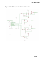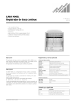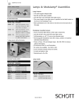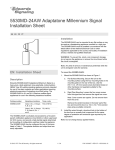
1
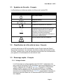
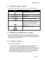
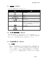
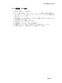
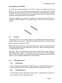
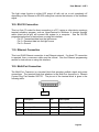
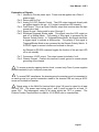
SCHOTT North America, Inc.
Part number:
Serial number:
A20970
LLS 3
LED Light Source
User Manual
SCHOTT North America, Inc.
122 Charlton Street, Southbridge, MA 01550-1960
Phone: (508) 765-9744, Fax: (508) 765-1299
Email: [email protected]
Website: www.schott-moritex.com
Table of Contents
1.0.
SAFETY WARNING – ENGLISH
4
1.1.
Safety Symbols – English
5
1.2.
LED Safety Classification – English
5
1.3.
Quick Start – English
5
2.0.
SICHERHEITSHINWEISE - DEUTSCH
7
2.1.
Sicherheitssymbole – Deutsch
8
2.2.
Sicherheitseinstufung des Lasers – Deutsch
8
2.3.
Schnellstart – Deutsch
8
3.0.
AVERTISSEMENTS DE SECURITE – FRANÇAIS
10
3.1.
Symboles de Sécurité – Français
11
3.2.
Classification de la Sécurité du Laser– Français
11
3.3.
Démarrage Rapide – Français
11
4.0.
ADVERTENCIA DE SEGURIDAD – ESPAÑOL
13
4.1.
Símbolos de Seguridad – Español
14
4.2.
Clasificación de Seguridad del Láser – Español
14
4.3.
Inicio Rápido – Español
14
5.0.
安全上の警告 – JAPANESE
16
5.1.
安全記号 – Japanese
17
5.2.
レーザー安全性分級 – Japanese
17
5.3.
クイックスタート – Japanese
17
6.0.
GENERAL INSTRUCTIONS
19
6.1.
Product Description
19
6.2.
Installation Guidelines
20
User Manual - LLS 3
6.3.
Cleaning
21
6.4.
LED Specifications
21
7.0.
LLS 3 – LED LIGHT SOURCE OPERATION
22
7.1.
General Operation
22
7.2.
Front Panel Controls
22
8.0.
USER CONTROL AND OPERATING MODES
23
8.1.
User Control Modes
22
8.2.
Operating Modes
22
9.0.
REMOTE POLARITY SWITCH
25
10.0. RS-232 CONNECTION
26
11.0. ETHERNET CONNECTION
26
12.0. MULTI-PORT CONNECTION
26
13.0. REMOTE OPERATION: RS-232
29
14.0. REMOTE OPERATION: ETHERNET
36
15.0. POWER SUPPLIES
37
16.0. TROUBLESHOOTING
38
17.0. PRODUCT SPECIFICATIONS
39
18.0. DECLARATION OF CONFORMITY
40
19.0. REPLACEMENT PARTS LIST
41
20.0. SUPPORT, SERVICE, AND RMA POLICY
41
21.0. WARRANTY AND LIABILITIES
42
Page 3
User Manual - LLS 3
1.0. Safety Warning – English
1.
2.
3.
4.
5.
6.
7.
8.
9.
10.
11.
Read, understand and follow all instructions in this manual.
Keep all safety and operating instructions for future reference.
!
To ensure protection from electric shock, only power the LED Light
Source from an agency approved Class 2 DC power supply (double insulation)
such as the one included with the product.
!
Never look directly at the LED output when on. LEDs feature a very high
luminance that can cause eye injury. Do not look at beam with optical
instruments. Use UV protective goggles when using a UV Light Source.
!
Do not cover the front or the rear of the unit.
To ensure proper grounding, use the supplied ESD grounding connections.
Use only power cords with appropriate connectors for secure use.
Disconnect power cord when unit will be left unused for long periods of time.
Do not use this unit near any liquids or in an area with excessive moisture.
Do not place flammable materials on or near the unit.
Use only standard glass type cleaners. Do not use solvents or petroleum
distillates or any volatile or flammable liquids or foams.
12. Never spill liquid on the unit.
13. Unplug before servicing (servicing is for authorized personnel only).
14. Do not service the unit beyond that described in this manual. Return the light
source to an authorized service center. For a Return Material Authorization,
see Section 20.
Page 4
User Manual - LLS 3
1.1. Safety Symbols – English
The following Symbols are used in relation to the LED Light Source.
Symbol
Explanation
Unit ON/Standby
DC Power
DC Polarity
European Declaration of Conformity
Compliant with the Waste Electrical and
Electronics Equipment/Restriction of the Use
of Certain Hazardous Substances in Electrical
and Electronics Equipment (WEEE/RoHS)
recycling directives.
Optical Radiation Safety
1.2. LED Safety Classification – English
The LED Light Source is classified as a Type 1 LED Product. Do not stare into
the beam. LED output is out of the front nosepiece of the unit. Please follow all
safety and operational guidelines to ensure safe operation of the unit.
1.3. Quick Start – English
1.3.1. Input Voltage
The LLS 3 accepts input voltage up to 35 VDC. DC power for the LED Light
Source must be from an agency approved Class 2 DC power supply. A
suitable 24VDC power supply for 100 to 240 VAC and 50/60 Hz is provided
with the unit. Input voltage can be applied to either the circular DC connector
or the green terminal block (Multi-Port connector). It is advised that the
chassis ground terminal on the Multi-Port connector be attached to a suitable
earth ground.
Page 5
User Manual - LLS 3
1.3.2. Turning the Light Source “On”
1.
2.
3.
4.
5.
6.
7.
Connect the cord from the power supply to the light source.
The LLS 3’s green status LED will illuminate for a few seconds while the
unit initializes. If the unit is in Standby Mode, then the LED will turn off.
Turn the intensity control knob all the way down (to prevent accidentally
shining the optical output onto others).
Press the On/Standby push button on the front of the unit.
Turn up the intensity control knob.
If the light engine does not light up, check the polarity switch setting.
To turn the LED Off, press the On/Standby push button on the front of
the unit.
Page 6
User Manual - LLS 3
2.0. Sicherheitshinweise - Deutsch
1.
2.
3.
Bitte lesen Sie dieses Handbuch vollständig durch und befolgen Sie alle darin
enthaltenen Anweisungen.
Bewahren Sie alle Sicherheitshinweise und Betriebsanweisungen zum
späteren Gebrauch sorgfältig auf.
!
Zum Schutz vor Stromschlägen sollte die LED-Leuchte ausschließlich mit
einem behördlich zugelassenen Gleichstrom-Netzteil der Klasse 2 (doppelt
isoliert) betrieben werden. Das mitgelieferte Gerät entspricht der behördlichen
Anforderungen.
4.
5.
6.
7.
8.
9.
10.
11.
12.
13.
14.
!
Blicken Sie nie direkt in die eingeschaltete LED-Lichtquelle. LEDLeuchten verfügen über einen sehr hohen Helligkeitsgrad und können zu
Augenverletzungen führen. Betrachten Sie den Lichtstrahl nicht mit optischen
Instrumenten. Verwenden Sie beim Einsatz von UV-Leuchten immer eine
Schutzbrille gegen die UV-Strahlung.
!
Die Vorder- und Rückseite des Geräts bitte nicht abdecken.
Zur sicheren Erdung nur das mitgelieferte Erdungskabel zur elektrostatischen
Entladung verwenden.
Zum Zweck der Betriebssicherheit ausschließlich Anschlussleitungen mit den
passenden Steckvorrichtungen verwenden.
Wenn das Gerät über einen längeren Zeitraum nicht eingesetzt wird, bitte die
Stromversorgung unterbrechen.
Gerät nicht in der Nähe von Flüssigkeiten oder in übermäßig feuchten
Umgebungen einsetzen.
Lassen Das Gerät von entflammbaren Materialien entfernt halten.
Verwenden Sie bitte nur gewöhnliche Glasreiniger. Von der Verwendung von
Lösungsmitteln, Öldestillaten, flüchtigen oder leicht entzündlichen
Flüssigkeiten bzw. Schäumen ist abzusehen.
Vermeiden Sie das Verschütten von Flüssigkeiten auf dem Gerät.
Vor Wartungsarbeiten bitte den Stecker ziehen (Wartungsarbeiten dürfen nur
von entsprechend autorisiertem Personal vorgenommen werden).
Beschränken Sie Ihre Wartung des Geräts bitte auf das in diesem Handbuch
beschriebene Ausmaß. Geben Sie das Steuergerät an ein autorisiertes
Kundendienstcenter von SCHOTT zurück. In Abschnitt 20 finden Sie mehr
Informationen zur Rückgabegenehmigung für Materialien.
Page 7
User Manual - LLS 3
2.1. Sicherheitssymbole – Deutsch
Im Hinblick auf die LED-Lichtquelle werden die folgenden Sicherheitssymbole
verwendet:
Symbol
Erläuterung
Gerät einschalten/Standby
Gleichstrom
Gleichstrompolung
Europäisches Gütezeichen (CE-Kennzeichen)
Entsprechend der Richtlinien des
Europäischen Parlaments und des Rates zur
Beschränkung der Verwendung bestimmter
gefährlicher Stoffe in Elektro- und
Elektronikgeräten und über Elektro- und
Elektronik-Altgeräte (WEEE/RoHS).
Optischer Strahlungsschutz
2.2. Sicherheitseinstufung des Lasers – Deutsch
Die LED-Lichtquelle wird als Laserprodukt der Klasse 1 eingestuft. Nicht in den
Strahl blicken. Der Laserstrahl tritt am Objektiv an der Gerätvorderseite aus. Bitte
befolgen Sie zur Gewährleistung des sicheren Betriebs dieses Geräts alle
Sicherheits- und Betriebsanweisungen.
2.3. Schnellstart – Deutsch
2.3.1. Eingangsspannung
Die Laserlichtquelle kann mit einer Eingangsspannung von bis zu 35 Volt
Gleichstrom betrieben werden. Die Gleichstromversorgung der LaserLichtquelle ist über ein behördlich zugelassenes Gleichstrom-Netzteil der
Klasse 2 vorzunehmen. SCHOTT bietet ein hierfür zugelassenes 24VGleichstrom-Netzteil für 100 bis 240 V Wechselstrom und 50/60 Hz an. Die
Stromversorgung kann entweder über die runde Gleichstrombuchse oder die
grüne Klemmleiste (Multi-Port-Anschluss) erfolgen. SCHOTT empfiehlt den
Anschluss der Chassismasse-Klemme der Klemmleiste an eine geeignete
Erdung.
Page 8
User Manual - LLS 3
2.3.2. Einschalten des Steuergeräts
1. Schließen Sie die Lichtquelle an das Netzteil-Kabel an.
2. Die LLS 3 grüne Status-LED wird für ein paar Sekunden zu beleuchten,
während das Gerät initialisiert. Wenn sich das Gerät im Standby-Modus
wird die LED erlischt.
3. Drehen Sie den Intensitätsregler ganz herunter (zur Verhinderung des
versehentlichen Auftreffens des Laserstrahls auf eine Person).
4. Betätigen Sie den Einschalt-/Standby-Knopf an der Vorderseite des
Geräts.
5. Drehen Sie den Intensitätsregler wieder herauf.
6. Wenn der Leuchtkopf nicht aufleuchtet, Einstellung des Polaritätsschalters
überprüfen.
7. Zum Ausschalten der LED-Leuchte wieder den Einschalt-/Standby-Knopf
an der Gerätvorderseite betätigen.
Page 9
User Manual - LLS 3
3.0. Avertissements de sécurité – Français
1. Lisez, comprenez et suivez toutes les instructions dans ce manuel.
2. Gardez toutes les consignes de sécurité et opérationnelles pour référence
future.
3.
4.
!
Afin de garantir la protection contre le choc électrique, alimenter la source
de la lumière du DEL uniquement avec un bloc d’alimentation CC de Classe 2
approuvé par une agence (double isolement) tel que celui inclus avec le produit.
!
Ne jamais regarder directement la sortie du DEL lorsqu’elle est allumée.
Une des caractéristiques des DEL est une luminescence très forte qui peut
provoquer des blessures aux yeux. Ne pas regarder le faisceau avec des
instruments optiques. Utiliser des lunettes de protection contre les UV lors de
l’utilisation de la source de lumière UV.
!
Ne pas couvrir l’avant ou l’arrière de l’unité.
5.
6. Pour garantir une correcte mise à la terre, utiliser le conducteur de terre ESD
fourni.
7. Utiliser uniquement des cordons d’alimentation avec connecteurs appropriés
pour une utilisation en sécurité.
8. Déconnecter le cordon d’alimentation lors d’une inutilisation prolongée.
9. Ne pas utiliser cette unité à proximité de tout type de liquide ou dans une zone
trop humide.
10. Ne pas placer de matériaux inflammables sur ou à coté de l’unité.
11. Utiliser seulement des nettoyeurs pour type de verre standard. Ne pas utiliser
de solvants ou distillés de pétrole ou tout liquide ou mousse inflammable ou
volatile.
12. Ne jamais déverser du liquide sur l’unité.
13. Débrancher avant l’entretien (l’entretien est uniquement pour le personnel
autorisé).
14. Ne pas effecteur la maintenance de l’unité en dehors de ce qui est décrit dans
ce manuel. Ramener le contrôleur à un centre de service autorisé. Pour une
Autorisation de Retour Matériel, voir la Section 20.
Page 10
User Manual - LLS 3
3.1. Symboles de Sécurité – Français
Les Symboles sont utilisés en relation à la Source de Lumière DEL
Symbole
Explication
Unité ON/En attente
Courant en continu
Polarité CC
Déclaration Européenne de Conformité
Compatible avec les directives de recyclage
concernant l'équipement pour les déchets
électriques et électroniques/restriction à
l'utilisation de certaines substances
dangereuses dans l'équipement électrique et
électronique (WEEE/RoHS).
Sécurité Optique contre les Radiations
3.2. Classification de la Sécurité du Laser– Français
La source de lumière du DEL est classifiée comme Produit Laser de Classe 1.
Ne pas fixer le faisceau. La sortie laser est située au dehors de l’arcade frontale
de l’unité. Veuillez suivre toutes les instructions de sécurité et de fonctionnement
pour garantir un fonctionnement en sécurité de l’unité.
3.3. Démarrage rapide – Français
3.3.1. Voltage d’entrée
Le LLS 3 accepte un voltage d’entrée jusqu’à 35 VCC. L’alimentation CC
pour la Source de lumière du DEL doit arriver d’un bloc d’alimentation CC de
Classe 2 approuvé par une agence. SCHOTT offre un bloc d’alimentation
adapté de 24VCC pour un VCA de 100 à 240 et 50/60 Hz. Le voltage
d’entrée peut être appliqué soit au connecteur CC circulaire, soit au bloc
terminal vert (connecteur Multi-Porte). SCHOTT recommande de brancher le
terminal de terre du châssis sur le connecteur Multi-Porte à une mise à la
terre adaptée.
Page 11
User Manual - LLS 3
3.3.2. Allumer le Contrôleur
1. Connecter le cordon de l’alimentation à la source de lumière.
2. Le LLS 3 la LED verte s'allume pendant quelques secondes lorsque
l'appareil s'initialise. Si l'appareil est en mode veille, puis le voyant
s'éteint. 2.
3. Tourner le poignet de contrôle d’intensité complètement vers le bas (pour
prévenir l’illumination accidentelle de la sortie optique sur un tiers).
4. Appuyer sur le bouton On/Standby au front de l’unité.
5. Tourner vers le haut le poignet de contrôle d’intensité.
6. Si la tête de la lumière ne s’allume pas, vérifier le réglage de l’interrupteur
de polarité.
7. Pour éteindre le DEL, appuyer sur le bouton On/Standby au front de
l’unité.
Page 12
User Manual - LLS 3
4.0. Advertencia de seguridad – Español
1. Lea, comprenda y siga todas las instrucciones contenidas en este manual.
2. Guarde todas las instrucciones de seguridad y funcionamiento para su
referencia en el futuro.
3.
4.
!
Para garantizar protección contra electrocución, alimente la Fuente
Luminosa LED exclusivamente con una fuente de alimentación de c.c. clase 2
homologada (doble aislamiento) como la que viene incluida con el producto.
!
No mire directamente a la salida del LED cuando esté encendido. Los
LEDs se caracterizan por una luminancia muy alta que puede causar lesiones
oculares. No mire al haz con instrumentos ópticos. Utilice gafas protectoras UV
al utilizar la Fuente Luminosa UV.
!
5.
No cubra las partes frontal y trasera de la unidad.
6. Para garantizar que esté adecuadamente puesto a tierra, utilice el cable de
puesta a tierra ESD proporcionado.
7. Utilice exclusivamente cables de alimentación con los conectores adecuados
para un uso seguro.
8. Desenchufe el cable de alimentación cuando la unidad vaya a estar sin usar por
un tiempo prolongado.
9. No utilice esta unidad cerca de líquidos ni en un área con una humedad
excesiva.
10. No coloque materiales inflamables sobre la unidad ni cerca de ella.
11. Utilice exclusivamente limpiadores convencionales de cristal. No utilice
disolventes ni destilados del petróleo ni líquidos o espumas inflamables o
volátiles.
12. No derrame líquido sobre la unidad.
13. Desenchúfelo antes del mantenimiento (mantenimiento reservado
exclusivamente al personal autorizado).
14. No realice un mantenimiento de la unidad más allá de lo descrito en este
manual. Devuelva el controlador a un centro de servicio autorizado. Para una
Autorización de Material Retornable, véase la Sección 20.
Page 13
User Manual - LLS 3
4.1. Símbolos de seguridad – Español
Se utilizan los siguientes símbolos en relación con la Fuente Luminosa LED
Símbolo
Explicación
Unidad ENCENDIDA/en espera
Alimentación c.c.
Polaridad c.c.
Declaración Europea de Conformidad
Conforme a las directivas de reciclaje de
Equipos Eléctricos y Electrónicos Residuales
/Restricción del Uso de Determinadas
Sustancias Peligrosas en Equipos Eléctricos y
Electrónicos.
Seguridad de radiación óptica
4.2. Clasificación de Seguridad del Láser – Español
La Fuente Luminosa LED se clasifica como un producto láser de clase 1. No
mire al haz. La salida del láser se encuentra en el talón frontal de la unidad. Por
favor, siga todas las directivas de seguridad y funcionamiento para garantizar un
funcionamiento seguro de la unidad.
4.3. Inicio Rápido – Español
4.3.1. Tensión de Entrada
El LLS 3 acepta una tensión de entrada de hasta 35 Vcc. La alimentación
c.c. de la Fuente Luminosa LED debe provenir de una fuente de
alimentación c.c. de clase 2 homologada. Una fuente de alimentación de 24
Vcc adecuada para entre 100 y 240 Vca y 50/60 Hz se ofrece. La tensión de
entrada se puede aplicar tanto al conector c.c. circular como al bloque
terminal verde (conector multipuerto). Se aconseja unir el terminal de tierra
del chasis del conector multipuerto a una tierra adecuada.
Page 14
User Manual - LLS 3
4.3.2. “Encendiendo” el Controlador
1. Conecte el cable de la fuente de alimentación a la fuente luminosa.
2. El LLS 3 del LED de estado verde se ilumina durante unos segundos
mientras la unidad se inicializa. Si la unidad está en modo en espera, el
LED se apagará.
3. Baje del todo el selector de intensidad (para prevenir que se dirija
accidentalmente la salida óptica hacia una persona).
4. Pulse el botón de Encendido/En espera situado en la parte frontal de la
unidad.
5. Suba el selector de intensidad.
6. Si el cabezal luminoso no se enciende, compruebe la configuración del
conmutador de polaridad.
7. Para apagar el LED, pulse el botón de Encendido/En espera situado en
la parte frontal de la unidad.
Page 15
User Manual - LLS 3
5.0.
5.0. 安全上の警告 – Japanese
1.
この手引書をよくお読みになり、記述された全ての指示に従ってください。
2. 今後参照するために、全ての安全及び取扱説明書を保管してください。
3.
4.
5.
!
感電の危険から身を守るために、本製品と共に納品されたものと同様の、行政機
関の認可した第 2 級直流電力引き込み装置(2重絶縁)のみ LED 光源の電力供給に使
用して下さい。
!
光源が発光しているときは、 LED 出力部に決して直接目を向けないでく
ださい。LED は特徴として、目の損傷を招きかねない非常に高い輝度を持って
います。光学器械を使って光線を凝視しないでください。紫外線光源を使うと
きは、紫外線保護眼鏡を使用してください。
!
本装置の正面又は後部には何も被せないでください。
6. 適切なアースを確保するために、納品された ESD 接地ケーブルをご使用くださ
い。
7. 安全な使用のために、適正なコネクタの付いた電源コードのみをご使用くださ
い。
8. 装置を長時間使用しないときは、電源コードを抜いてください。
9. 本装置は、液体の近くあるいは湿度の高いエリアでは使用しないでください。
10. 本装置の上及び近くには、可燃性物質を置かないでください。
11. 一般的なガラス用クリーナーのみを使用してください。溶剤、石油留出物、あ
るいは揮発性又は可燃性の液体又は泡沫はいかなるものも使用しないでくださ
い。
12. 本装置の上に液体をこぼさないでください。
13. 整備・修理をする際には必ず電源コードを抜いてください(整備・修理は認可
された人員以外は行わないでください)。
14. 本手引書に記述された範囲を超える整備・修理は行わないでください。制御器
は、認可された サービス・センターに戻してください。器具返還認証
( Return Material Authorization)については 第 20 節をご覧ください。.
Page 16
User Manual - LLS 3
5.1. 安全記号 – Japanese
以下の記号が LED 光源に関して使用されています。
記号
説明
装置 ON/待機
直流電力
直流極性
欧州適合宣言
電気装置及び電子工学装置の廃棄処分/電気
装置及び電子工学装置内への特定の有害物質
の使用制限 (WEEE/RoHS) のリサイクリング
指令に準拠
光学放射安全性
5.2. レーザー安全性分級 – Japanese
LED 光源は第 1 級レーザー製品に分類されています。光線を凝視しないでくだ
さい。 レーザーは装置の正面先端部から出力されます。装置の安全な操作を確
保するために、 安全と運転に関する全ての指針に従ってください。
5.3. クイックスタート – Japanese
5.3.1. 入力電圧
LLS 3 は、最高 35 VDC までの入力電圧で使用出来ます。 LED 光源用の直
流電力は、 は 100 から 240 VAC 及び 50/60Hz で使用可能な 24VDC の AC
アダプターを提供しています。入力電圧は 円形直流コネクタ又は緑色端子
ブロック (マルチポートコネクタ)のどちらにも通せます。. は、マルチポー
トコネクタ上のシャシー接地端子を適正なアースに取り付けることをお勧め
します。
Page 17
User Manual - LLS 3
5.3.2. 制御器を “On”に回す
1. LLS 3 に電源コードを接続する。
2. は、 LLS 3 の緑色のステータスは、ユニットの初期化を数秒間 LED が点
灯し ます。ユニットの場合、スタンバイモードにしてからは、 LED の電
源を切るということです。
3. 強度調節つまみを反時計回り一杯に回して MIN の設定にする (誤って人員
に光が照射するのを防ぐため)。
4. 装置正面の ON/OFF ボタンを押す。
5. 強度調節つまみを回して明るさを調整する。
6. LED が点灯しない場合は、極性スイッチの設定をチェックする。
7. LED を消すには、装置正面の ON/OFF ボタンを押す。
Page 18
User Manual - LLS 3
Technical References
6.0. General Instructions
6.1.
Product Description
Congratulations on the purchase of the LLS 3 LED Light Source, the state of the art in
light output and control, utilizing a simplified user interface with versatile remote control
abilities. The LLS 3 is compatible with all standard COLDVision Series light guides.
Optimal performance is achieved when coupled with larger bundle diameters, 9-14mm.
The LLS 3 (A20970) was initially available in White with two different color temperature
options, Cool (6,000 K) and Warm (3,100 K). The flagship Cool White model boasts
light output equal to 150W DDL Halogen lamp levels. With the latest product updates, a
number of wavelengths including red, green, and blue are now available on the LLS 3
platform. Solutions with other wavelengths can be produced to match specific customer
application requirements, even in the non-visible UV and IR ranges.
The LLS 3 has several advanced features including:
• Various remote control abilities: Ethernet, RS-232, and analog 0-5V
• Triggered strobe up to 1 kHz
• Auto sensing inputs with front control lockout via Ethernet and RS-232
The Triggered Strobe Mode allows for overdriving the LED for a brief, controlled period.
The strobe intensity can be up to 200% of the Normal Mode intensity. Strobe on time
and delay time are adjustable via Ethernet and RS-232 commands. The strobe pulse
triggered polarity can be adjusted by the position of the polarity switch on the rear panel
of the unit.
Auto sensing inputs allows for the light source to automatically switch between the
various means of control (front panel intensity control knob, Ethernet, RS-232, and
remote analog 0-5V) without the need to specify the control mode in advance. The light
source senses which control interface is active and automatically uses that interface to
adjust the light intensity. In addition, the front control interface can be locked out via
Ethernet or RS-232 commands. The Ethernet and RS-232 interfaces also provide
continuous monitoring of LED temperature and light source status.
The LLS 3 is an intelligent light source that allows unparalleled flexibility. The LLS 3
can be configured to remember its operating state when power is removed and restores
the state when power is re-applied. This feature can be toggled on or off through
Ethernet and RS-232 commands. It is also possible to restore the light source to a predetermined state when a control system dictates, utilizing a single command.
The RS-232 and Ethernet demo program/software can be downloaded from the
website or obtained from sales/customer service. Please contact us for updates.
http://www.schott-moritex.com/us/english/syn/products/light_sources/index.html
Page 19
User Manual - LLS 3
6.2.
Installation Guidelines
Front
Right
Top
To insure proper operation of your LLS 3 – LED Light Source, the following
conditions must be met:
•
•
•
•
•
•
For indoor use only, Installation Category, II; Pollution degree, 2
Maximum Operating Altitude: 2000 Meters
Minimum Clearances: Rear 3” (76 mm)
Do not cover the rear air exhaust port or the front air intake port
Avoid areas of excessive vibration
Operate the light source only in an environment where people do not
require protective equipment
Page 20
User Manual - LLS 3
Mounting Brackets, A20955
To install the mounting brackets to the LLS 3, remove the rubber feet from the
bottom of the unit. Then screw the mounting plate to the light source housing
matching the threaded holes and the four counter bored holes towards the center of
the plate. The four outer holes of the mounting plate can be used to install the light
source/mounting plate system into any machine.
These two brackets are mounted to a panel via 4 screws that are positions in a
rectangular fashion spaced 5.3" (front-back) length of the unit and 5.5" left-right of
the unit.
6.3.
Cleaning
The housing and the front and back plates have a durable finish that should retain its
original luster for many years. Cleaning the exposed areas with a commercial glass
cleaner will help to maintain the finish.
Before beginning, remove the cord from the light source. Wipe the exposed areas of
the housing and front and back plates with a soft cloth or paper towel moistened with
a commercial glass cleaner.
CAUTION: Do not use detergents, excess water, treated cloths, harsh cleaning or
flammable agents or sprays. If fluid spills into the interior, let the unit dry thoroughly
before using. Periodically, any visible dust accumulation should be removed using a
vacuum or commercially available can of compressed air.
6.4.
6.4.1.
LED Specifications
LED Lifetime
The LLS 3 features advanced technology high output, long-life LED light engines
that are operated at a very efficient power level below their maximum rating.
6.4.2.
LED Stabilization
The LED output will vary slightly after initial power on. Please allow one minute for
the LED light to achieve stable light output.
Page 21
User Manual - LLS 3
7.0.
7.1.
LLS 3 – LED Light Source Operation
General Operation
The LLS 3 has a simplified user interface for easy startup operation. To use the light
source in normal operation, press the On/Standby push button and adjust the
intensity control knob. If the light output does not come on, ensure the correct
setting of the rear polarity switch (see section 9.0 for more information). More
advanced control of the light source is available through the three remote control
interfaces.
When power is first applied to the unit, the green status indicator illuminates for a
few seconds while the unit initializes. After initialization, the unit will either be in
Standby Mode or On Mode depending on the last state that the unit was left in when
power was removed.
7.2.
Front Panel Controls
On/Standby
Push Button
Status
Indicator
Intensity
Control Knob
On/Standby Push Button:
Press and release to turn the LED on or off. Pressing the push button places the
unit in Local Mode. The ability to turn the LED on or off manually can be locked out
via RS-232 or Ethernet.
Status Indicator:
Indicates the status of the light source. When the status LED is off, the unit is in
Standby Mode. A steady on means the unit is on. Flashing means there is an error.
Intensity Control Knob:
Turn to adjust the intensity of the light output. If the unit is not in Local Mode, turn
the knob full right or left to place the unit in Local Mode. Auto-switching to Local
Mode can be locked out via RS-232 or Ethernet.
Page 22
User Manual - LLS 3
8.0. User Control and Operating Modes
There are four modes of user control of the light source: Local, Ethernet, RS-232, &
Analog and two modes of operation. The LLS 3 can switch between any of the 4 control
modes automatically. There is no need for a remote/local switch. Simply start using the
interface and the LLS 3 will track changes to that interface until another interface is
utilized. The front intensity knob and the analog input controls can also be locked out to
prevent users from making unauthorized light changes.
A command to the Ethernet or RS-232 interface switches to the corresponding
interface. To switch to Local Mode, adjust the front intensity control knob either fully
clockwise or fully counter-clockwise. To switch to Analog Lode, apply a large voltage
swing to the Multi-Port connector’s analog input pin (i.e., adjust from 0V to 5V or 5V to
0V). After the large voltage swing, adjust the control voltage to the desired level.
8.1
User Control Modes
Local Control Mode:
In Local Mode, the light source output is adjusted via the front intensity control knob
and the light source is turned on or placed in standby via the front push button.
Local Mode can be locked out via Ethernet or RS-232 commands.
Ethernet Control Mode:
In Ethernet Mode, the light source functionality is controlled via the Ethernet
connector. See the Ethernet programming section for instructions on how to use this
interface.
RS-232 Control Mode:
In RS-232 Mode, the light source functionality is controlled via the RS-232
connector. See the RS-232 programming section for instructions on how to use this
interface.
Analog Control Mode:
In Analog Mode, the light source output is controlled via the green Multi-Port
connector’s analog input pin. Analog Mode can be locked out via Ethernet or RS232 commands.
8.2
Operating Modes
There are two modes of operation: Normal Mode and Triggered Strobe Mode.
Normal Mode:
In Normal Mode, the output intensity is controlled from 0-100% using any of the four
user control modes. In Normal Mode, the light output can be turned on and off using
the shutdown pin on the Multi-Port connector. Polarity of the shutdown signal can
be changed using the rear polarity switch.
Page 23
User Manual - LLS 3
Triggered Strobe Mode:
Triggered Strobe Mode is activated via the Ethernet or RS-232 interface. In this
mode, the light output pulses once for every triggered signal that is received on the
shutdown pin on the Multi-Port connector. The light output’s on-time and delay time
are adjustable via Ethernet or RS-232. In Triggered Strobe Mode, the intensity of
the light output pulse can be setup to achieve greater levels than the Normal Mode
intensity. The Triggered Strobe Mode capabilities are: Max 1 kHz pulse rate, max
pulse width 1ms, 10% duty cycle.
Back Panel Controls
Power
Input
RS-232
Multi-Port
Chassis GND
#6-32 THRD
Polarity
Switch
Ethernet
Power Input:
The power input accepts a 5.5 mm barrel power plug with 2.1mm pin diameter, center
positive. The voltage input range is from 12 to 28 volts, but the voltage must be more
than the LED’s forward voltage to ensure proper performance. To be safe, use 24V
input voltage regardless of LED color or specific wavelength.
Strobing of the LLS 3 can be done with a 24V input; however, overdriving the LED to
twice the Normal Mode power is not possible unless at least 26V is applied. With a 24V
input voltage, some overdrive power is possible, but not twice the input power. An easy
way to power the unit for Strobe Mode is to use both rails of a +/- 15V power supply for
a total of 30V.
Multi-Port:
The Multi-Port connector is used for multiple signal input/output. Main power input can
be supplied using this connector instead of the power input connector. Other signals
available include: Analog 0-5V remote input, shutdown/trigger signal, and a fault signal.
There is also a convenient 5V DC output available and chassis ground connection (to
properly ground the chassis to earth ground). See Section 12.0 for pin-out information.
Page 24
User Manual - LLS 3
Equalizer Light Feedback:
Although LED’s do not vary in light intensity over time as drastically as other lighting
technologies, the LED light engine will slowly degrade as it ages.
The LLS 3 has a built in photo sensor that monitors the light output and can be used to
maintain a constant light output during the use of the LED. See the RS-232
programming section on how to activate and use the equalizer.
Once activated, the LLS 3 will maintain a constant light output for a given setting for any
of the 4 control modes. The equalizer will automatically obtain new set-points whenever
a new RS-232 or Ethernet intensity is set. If the intensity needs to be changed by the
analog or front intensity knob modes, then the equalizer should be turned off, the
intensity adjusted, then turned on again.
Note that this feature is not intended to be used for startup conditions. LED light output
will drift considerably in the first few minutes of turn on. The use of this feature is to
maintain stabilized light over long periods of time.
Resetting to Factory Defaults:
There are two means of resetting the factory defaults:
• Utilize the factory reset command via RS-232 or Ethernet
• Press and hold the On/Standby button for 10 seconds while power is applied
9.0. Remote Polarity Switch
The setting of this switch determines how the remote input affects the system.
Polarity
Setting
–
(Left)
+
(Right)
Mode
Remote Trigger Input
Light Output
Voltage Circuit
Connected
Low Voltage (Sinking)
OFF
Voltage Input > 1V
ILLUMINATED
Contact Circuit
Connected
Open
ILLUMINATED
Closed
OFF
Voltage Circuit
Connected
Low Voltage (Sinking)
ILLUMINATED
Voltage Input > 1V
OFF
Contact Circuit
Connected
Open
OFF
Closed
ILLUMINATED
Please note:
If the Remote Input is not being used, then the Polarity Switch should be left in the (-)
position. If the switch is in the (+) position, the head will not illuminate if nothing is
connected to the Shutdown/Triggered Strobe pin of the Multi-Port.
Page 25
User Manual - LLS 3
The light output function is either LED output off with unit on or unit completely off
depending on the Ethernet or RS-232 setting that controls the behavior of the shutdown
signal.
10.0. RS-232 Connection
This is a 9 pin ‘D’ socket for direct connection to a PC, Laptop or other device running a
terminal emulation program, such as HyperTerminal in Windows. A ‘straight through’
cable (wired pin-for-pin) will connect the system to a computer. See the RS-232
programming section for instructions on using this interface.
Pin 2 = Transmitted data from the light source
Pin 3 = Received data into the light source
Pin 5 = Ground
11.0. Ethernet Connection
This is an RJ45 Ethernet connection to an Ethernet network. If a direct PC connection
is required, then a crossover cable must be utilized. See the Ethernet programming
section for instructions on using this interface.
12.0. Multi-Port Connection
The Multi-Port Connector is a terminal block that provides multiple signal and power
connections. The terminal block that attaches to the Multi-Port connector is: Phoenix
Contact Plug Part Number 1827761. The pin-out of the terminal block is given in the
following table:
Pin 1
Pin
Description
Pin
Description
1
Power Input
5
Signal GND
2
3
Power Input Return
Analog Input
6
7
Shutdown/Triggered Strobe
+5 VDC
4
Fault Output
8
Chassis GND
Page 26
User Manual - LLS 3
Explanation of Signals:
Pin 1 Identical to Circular power input. Power must be applied via a Class 2
power supply.
Pin 2 Return path for Pin 1.
Pin 3 Analog 0-5 VDC Remote Control. The LED output responds linearly with
an applied signal to this pin. A 5V signal is maximum LED intensity.
Pin 4 Fault Output. This is an Open Collector output that is active when the light
source has a fault.
Pin 5 Signal Ground. Return path for pins 3 through 7.
Pin 6 Shutdown/Triggered Strobe signal. This signal turns the LED output on
and off in Normal Mode. The polarity of this signal is governed by the
Remote Polarity Switch. In Triggered/Strobe Mode, this signal should be
a trigger signal to activate a strobe pulse. The polarity of this signal in
Triggered/Strobe Mode is also governed by the Remote Polarity Switch. A
5-24VDC signal or contact closure can be used on this pin.
An Ethernet or RS-232 command toggles the function of this pin from LED
off to unit standby.
Pin 7 Convenient +5VDC output. The output current is limited to 1mA.
Pin 8 Chassis Ground. Connect this terminal to earth ground to ensure proper
grounding of the chassis.
!
To ensure protection against electric shock, connect only Class 2 power supplies
(double insulation) to pin1 and pin2 power pins.
!
To ensure EMC compliance, the chassis ground connection must be connected to
an earth ground or a ground connection made to the chassis PEM nut using a #6-32
screw and toothed lock washer.
!
Signal wiring to the Multi-Port terminal block (pins 3-8) must be rated for at least
200 mA, 30V. The power input wiring (pins 1 and 2) must be rated for at least 1.5
amps, 50V. The temperature rating of all wiring should be 70°C or greater. The
Phoenix Contact Terminal Block is rated for 16-28 AWG solid or stranded wire.
Page 27
User Manual - LLS 3
Representative Schematic of the Multi-Port Connector:
Page 28
User Manual - LLS 3
13.0 Remote Operation: RS-232
The LLS 3 LED Light Source can be operated remotely via a built-in RS-232 interface.
Power must be applied to the unit to use this interface but the light source does not
need to be turned on. Connect the RS-232 DTE equipment to the light source (DCE)
using a 9 pin straight-through cable. An example Windows Dialog based application
that shows typical RS-232 communication is available on the website and by request.
The terminal emulation settings for communications are as follows:
• 9600 Baud rate
• 8 Bits
• No Parity
• No Handshaking
All commands are acknowledged by a <Carriage return> character or a response from
the command terminated by <CR>.
Command Protocol
Any device that can transmit and receive ASCII characters through RS232 can remotely
control the LED Light Source. The format for most command strings are: &yxx<CR>, where
& = header character
y = command character
xx = one or two character command parameter
<CR> = carriage return character “/r”
When sending commands, there are certain characters that must be sent in order for a
command to function. Single digit values must be preceded by zeros if the parameter field
requires multiple characters. For example, setting the lamp intensity to zero is: &i00.
Commands are not case sensitive. The LLS 3 buffers ASCII characters until a carriage return
is received. The buffer is automatically cleared after a command is processed. Invalid
commands are also cleared by receiving a carriage return or after a 10 second command
timeout.
Negative Acknowledgements
Negative acknowledgements are used to indicate that a received command was invalid. The
following negative acknowledgements are supported.
i.
ii.
iii.
Invalid Command: Not a recognized command: &ncx
1. c = constant character denoting command not recognized
2. x = command character received
Invalid Parameter: A command parameters is invalid: &nypxx
1. y = command character
2. p = constant character denoting invalid parameter error
3. xx = received data
4.
Value Out of Range: Value of the command parameter exceeds the command‘s range: &nyrxx
1. y = command character
2. r = constant character denoting out of range
3. xx = received data
Page 29
User Manual - LLS 3
iv.
v.
Not in Correct Mode: Some commands require a specific mode before the value can be altered:
&nym
1. y = command character
2. m = constant character denoting not in correct mode
Command Timeout: If a command is not completed (i.e., a <CR> is not sent) within 10 seconds
of when the first character is received by the LLS 3 : &ni
Command Summary
Activate/Deactivate UDP-Netfinder
“&afx”
x=0,1,?
Get Dynamic Ethernet Gateway Address
“&agd”
Get/Set Static Ethernet Gateway Address
&agsxxx:xxx:xxx:xxx”
xx’s = address or ?
Get Ethernet Dynamic IP Address
“&aid”
Get/Set Ethernet Static IP Address
“&aisxxx:xxx:xxx:xxx”
xx’s = address or ?
Get Dynamic Ethernet Subnet mask
“&asd”
Get/Set Static Ethernet Subnet maskic
“&assxxx:xxx:xxx:xxx”
xx’s = address or ?
Get/Set Ethernet DHCP mode
(and reset of network interface)
“&am”
x=0,1,2?
Get/Set TCP Port
“&apx“
Get Ethernet link status
“&au”
Get Light Source Status
“&c”
Get LED Temperature
“&ct”
Get/Set Equalizer Mode Control
“&ex”
x=0,1,?
Get/Set Equalizer Calibration value
“&ebxxx”
xx=000-F7F, ?
Perform Equalizer Auto-Calibration
“&ec”
Get Equalizer internal intensity value
“&ed”
Get/Set Equalize Loop Process Value
“&ee”
Get/Set Equalizer Hold
“&eh”
Get/Set Equalizer Init Delay
“&ei”
Get Equalizer Meter Value
“&ev”
Get Equalizer Stability Value
“&es”
Get Firmware Level
“&f”
Get/Set Lamp Intensity:
“&ixx”
Get/Set Shutdown signal behavior
“&jx”
Get/Set Front Panel Controls and Analog Input Lock:
“&kx”
Get/Set Light Source ON/OFF:
“&lx”
Get Light Source Control Mode
“&m”
Restore Factory Defaults:
“&o”
Restore Factory Defaults but preserve network settings:
“&o2”
Get/Set Triggered Strobe Intensity:
“&pixx”
Get/Set Triggered Strobe Delay:
“&pdxxxx”
Get/Set Triggered Strobe On-Time:
“&poxxxx”
Get/Set Triggered Strobe Mode:
“&pmx”
Get Device Name Query:
“&q”
Get/Set Restore Settings on Power Up:
“&rx”
Get/Set Save Settings After Each change:
“&sx”
Restore Settings Now (if &r=0):
“&t”
Get Light Source Serial Number:
“&z”
xx=00-FF, ?
x=0,1,?
x=0,1,?
x=0,1,?
xx=00-FF, ?
xxxx = 0000 – 9999, ?
xxxx = 0050 – 1000, ?
x=0,1,?
x=0,1,?
x=0,1,?
Page 30
User Manual - LLS 3
Command Details
i.
Activate/Deactivate UDP-Netfinder
&afx
Activates/Deactivates Netfinder protocol. This allows for using UDP to find LLS 3 devices
on a network. Netfinder adds processing time and slows down other functions of the LLS
3. It is recommended to deactivate if not required.
x = command parameter
0 = Netfinder off
1 = Netfinder on (factory default)
? = query value
return value: &afx where “x” is either 0 or 1 depending on whether or not Netfinder is
active.
ii.
Get Dynamic Ethernet Gateway Address
&agd
Gets the network interface’s Dynamically assigned gateway address
return value: &agdxxx:xxx:xxx:xxx where “xxx:xxx:xxx:xxx” is the network gateway
address. If in static mode the LLS 3 will return “&agd000:000:000:000”.
iii.
Get/Set Static Ethernet Gateway Address &agsxxx:xxx:xxx:xxx
Gets/Sets the network interface’s static gateway address
xxx:xxx:xxx:xxx = Network Gateway. Must enter 0’s for single and double digits. For
example, &ags192:168:000:001. Value of “xxx” is between 000 and 255
? = query network Gateway, “&ags?”.
return value: &agsxxx:xxx:xxx:xxx where “xxx:xxx:xxx:xxx” is the network gateway
address.
Factory Default is: 192:168:000:001
iv.
Get Dynamic Ethernet IP Address &aid
Gets the network interface’s Dynamically assigned IP address
return value: &aixxx:xxx:xxx:xxx where “xxx:xxx:xxx:xxx” is the network gateway
address. If in static mode the LLS 3 will return “&aid000:000:000:000”.
v.
Get/Set Static Ethernet IP Address &aisxxx:xxx:xxx:xxx
Gets/Sets the network interface’s static IP address
xxx:xxx:xxx:xxx = Network IP address. Must enter 0’s for single and double digits. For
example, &ais192:168:000:002. Value of “xxx” is between 000 and 255
? = query network IP address, “&ais?”.
return value: &aisxxx:xxx:xxx:xxx where “xxx:xxx:xxx:xxx” is the network IP
address.
Factory Default is: 192:168:000:002
vi.
Get Dynamic Subnet Mask &asd
Gets the network interface’s Dynamically assigned Subnet Mask
return value: &asdxxx:xxx:xxx:xxx where “xxx:xxx:xxx:xxx” is the network Subnet Mask.
If in static mode the LLS 3 will return “&asd000:000:000:000”.
vii.
Get/Set Static Ethernet Subnet Mask
&assxxx:xxx:xxx:xxx
Gets/Sets the network interface’s static Subnet Mask
xxx:xxx:xxx:xxx = Network Subnet Mask. Must enter 0’s for single and double digits. For
example, &ass255:255:255:000. Value of “xxx” is between 000 and 255
? = query network Subnet Mask, “&ass?”.
return value: &assxxx:xxx:xxx:xxx where “xxx:xxx:xxx:xxx” is the network Subnet Mask.
Factory Default is: 255: 255: 255:000
viii.
Get/Set Ethernet DHCP Mode (and reset of network interface)
Sets the network DHCP mode
x = command parameter
0 = DHCP off
1 = DHCP on (factory default)
&amx
Page 31
User Manual - LLS 3
2 = Re-acquire settings. If in static mode, resets Ethernet connection
? = query value
return value: &amx where “x” is either 0 or 1depending on whether the light source is set
to use DHCP or not.
ix.
Get/Set TCP Port &apxxxxx
Sets the Ethernet TCP Port used for communication. It’s not advised to change this
unless communication conflicts exist on the network.
xxxxx = 5 character port. Range: 00001 to 65535
? = query value
return value: & apxxxxx where “xxxxx” is the TCP Port
Factory Default is: 50811
x.
Get Network Link Status
&au
return value: & aux where “x” is the status:
0 = No Ethernet Link present
1 = Ethernet Link present
xi.
Get Light Source status
&c
Returns fault conditions that may be present:
return value:
&cxx where “xx” is the bit coded error code with values of:
bit 0 = Fan Fault
bit 1 = LED Overtemperature
bit 2 = LED Overcurrent (failure of LED drive circuit)
bit 8 = Indicates that one of the above faults exists.
xii.
Get LED Temperature
&ct
Returns temperature of the LED:
return value:
&ctxx where “xx” is the LED temperature in Celcius
xiii.
Get/Set Equalizer Mode Control
&ex
Sets the Equalizer Mode
x = command parameter
0 = Equalizer off
(factory default)
1 = Equalizer on
? = query value
return value: &ex where “x” is either 0 or 1 depending on whether the light source is in
Equalizer Mode.
xiv.
Get/Set Equalizer Calibration value: &eb
The LLS 3 is set at the factory to maximize the response of the light sensor. For the best
equalizer performance it’s important to maintain as close to a 12 bit value response for
the maximum light output. Therefore with the intensity set to maximum intensity, the light
value returned with the “&ev” command should be about 0xF7F. The auto calibration
function is used to automatically set this value. However, it can be manually set with this
command. DO NOT leave this setting at maximum if the maximum light sensor value is
achieved at significantly less than maximum light intensity.
xxx = 12 bit command value in HEX
? = query value
return value: &ebxxx where “xxx” is the 12 bit value in HEX.
xv.
Perform Equalizer Autocalibration &ec
See calibration description for the “&eb” command above. Calibration is performed at the
factory. However, use this command if the LED intensity is significantly reduced due to
LED aging/degredation.
return value: &ec
Page 32
User Manual - LLS 3
xvi.
Get Equalizer Intensity Value
&ed
Obtains the equivalent intensity that the equalizer feedback loop is currently using to
maintain the light output control.
return value: &edxxx where “x” is a 12 bit HEX value corresponding to the intensity of the
light source that the equalizer is setting. A value of 000 is 0% and FFF is 100%.
xvii.
Get/Set Equalize Loop Process Value:
&eexxx
Internal process value used for the Equalizer feedback loop. When the Equalizer is
engaged the value of the photo sensor is stored in non-volatile memory and can be read
and set with this command.
xxx = 12 bit command value in HEX
? = query value
return value: &eexxx where “xxx” is the 12 bit process value in HEX.
xviii.
Get/Set Equalizer Hold
&eh
Hold equalizer. Light Source maintains Intensity when hold is enabled. The intensity
value can be obtained with the “&ed” command. Value not stored in non-volatile
memory.
x = command parameter
0 = Equalizer normal control
1 = Pause Equalizer from controlling light output. Light output will be allowed to
vary.
? = query value
return value: &eh where “x” is either 0 or 1 depending on the hold status.
xix.
Get/Set Equalize Initiate Time Delay:
&eixxx
Time delay between equalizer being turned on (&e command) and before equalizer
engages.
xxx = time in seconds. Range is 000 to 500 seconds.
? = query value
return value: &eexxx where “xxx” is delay time in seconds.
Factory Default is: 003 seconds
xx.
Get Equalizer Meter Value: &ev
Obtain raw photo sensor value.
return value: &evxxx where “xxx” is the 12 bit photo sensor value HEX.
xxi.
Get Equalizer Stability Value:
&es
Obtain Equalizer Stability.
return value: &esx where “x” indicates the stability of the equalizer.
0 = non stable
1 = Locked (stable)
2 = equalizer initiated. Waiting for timeout before engaging.
4 = Intensity too low. Intensity being increased.
6 = Intensity too high. Intensity being decreased.
8 = Overrange reached. Intensity too low to maintain stability.
10 = Underrange reached. Intensity too high to maintain stability.
xxii.
Get firmware version
&f
Obtain the firmware version of the unit.
return value: &fx.xx where “x.xx” represents the firmware version.
xxiii.
Get/Set Lamp Intensity:
&ixx
Sets the lamp intensity. 00 to FF is value in HEX. 00 = off, FF = full brightness
xx = command parameter, 8 bit value in HEX. (factory default) = 00
? = query value
return value: &ixx where “xx” is the 8 bit intensity value in HEX.
Page 33
User Manual - LLS 3
xxiv.
Get/Set Shutdown signal behavior: &jx
Dictates the behavior of the shutdown signal on the Multi-Port connector.
x = command parameter
0 = LED shutdown only (factory default)
1 = unit shutdown
? = query status
xxv.
Get/Set Front Panel Controls and Analog Input Lock: &kx
Locks out the front panel controls (potentiometer and On/Standby push button) and/or the
rear analog port:
x = command parameter
0 = no lockout (factory default)
1 = Front Panel Controls lockout (bit one)
2 = Analog Input lockout (bit two)
3 = Both Front Panel Controls and Analog Input lockout (bit one and two)
? = query status
return value: &kx where “x” is one of the values above depending on the lockout status.
xxvi.
Get/Set Light Source On/Off:
&lx
Sets or obtains the light source On/Standby.
x = command parameter
0 = off (factory default)
1 = on
? = query value
return value: &lx where “x” is either 0 or 1 depending on whether the light source is on or
in Standby Mode.
xxvii.
Get light Source Control Mode
&m
Returns control mode:
return value: &mxx where “xx” is the control mode code with values of:
00 = “Local Mode”
01 = “Analog Mode”
02 = “RS-232 Mode”
03 = “ETHERNET Mode”
xxviii.
Restore Factory Defaults
&o
Restores factory default settings.
return value: “&o”
xxix.
Restore Factory Defaults but preserve network settings
&o2
Restores factory default settings but preserve network settings.
return value: “&o”
xxx.
Get/Set Triggered Strobe Intensity: &pixx
Sets the triggered strobe intensity. The power value is twice the Normal Mode
value (&i command). For example, &pi7F is the same intensity as &iFF. Note
input voltage levels required for the white LLS 3 model in Section 17.0. 00 to ff is
8 bit value in HEX. 00 = off, FF = 200% of Normal Mode intensity. 100% of
Normal Mode intensity corresponds to a triggered strobe intensity of 0x7f
xx = command parameter
(factory default) = 00
return value: &pixx where “xx” is the intensity value in HEX.
xxxi.
Get/Set Triggered Strobe Delay:
&pdxxxx
Sets the triggered strobe delay in microseconds. 0000 to 9999 is the value in
microseconds (decimal).
Page 34
User Manual - LLS 3
xxxx = command parameter
(factory default) = 0000
return value: &pdxxxx where “xxxx” is the Triggered Strobe Delay in microseconds.
xxxii.
Get/Set Triggered Strobe On-Time: &poxxxx
xxxx = command parameter
0050 to 9999 is the value in microseconds (decimal)
(factory default) = 0050
return value: &poxxxx where “xxxx” is the Triggered Strobe Delay in microseconds.
xxxiii.
Get/Set Triggered Strobe Mode On/Off: &pmx
Activates/Deactivates Triggered Strobe Mode.
x = command parameter
0 = triggered strobe mode off
(factory default)
1 = triggered strobe mode on
? = query value
return value: &pmx where “x” is either 0 or 1 depending on whether the light source is in
Triggered Strobe Mode.
xxxiv.
Get Device Name Query
&q
Obtain device name. Useful for mixed light source technologies residing on the same
network.
return value: &qLED Light Source
xxxv.
Get/Set Restore Settings on Power Up:
&rx
By default, when the LLS 3 is turned on the settings for the light source is automatically
restored for the LLS 3. This behavior can be disabled with this setting. Use the
Restore Settings command (&t) to restore stored values when &r is set to off
x = command parameter
0 = off (factory default)
1 = on
? = query status
return value: &rx where “x” is either 0 or 1 depending on the setting.
xxxvi.
Get/Set Save Settings After Each change: &sx
Excessive writes to the FLASH memory for frequent changes for the light source should
be avoided. The LLS 3 will store settings after 10 seconds of inactive command
changes. The writing to non-volatile memory can be disabled with this setting. Note that
until the Save setting is set back on, the light source will not store changes to its
parameters.
x = command parameter
0 = off (factory default)
1 = on
? = query status
return value: &sx where “x” is either 0 or 1 depending on the setting.
xxxvii.
Restore Settings now
&t
Restores settings immediately to the LLS 3. This command is useful in conjunction with
the &r command. For example, a user may wish not to restore settings on power
applied but at a specific moment when dictated by the user.
return value: &t
xxxviii.
Get Light Source Serial Number
&z
Obtains the serial number of the LLS 3 (as indicated on the bottom of the unit).
return value: &zxxxxxx where “xxxxxx” represents a six digit serial number of the LED
light source.
Page 35
User Manual - LLS 3
14.0. Remote Operation: Ethernet
In order to communicate with the LLS 3 via Ethernet, the IP address of the unit must be
known. By default, the LLS 3 ships with DHCP enabled which grabs an address from a
DHCP server residing on the network. Should there be no DHCP server, the LLS 3 sets
its network interface to the default static network settings after an approximately 30
second timeout. The default settings are:
IP:
Gateway:
Subnet Mask:
192.168.0.2
192.168.0.1
255.255.255.0
The IP address can be determined either by reading it over the RS-232 port or by
scanning for the LLS 3 on the Ethernet network. The RS-232 port can also be used to
change the network settings of the LLS 3.
There are two methods for finding the LLS 3 using the scanning method. One uses
UDP and a proprietary protocol called Netfinder. Netfinder uses UDP port 3040. The
second method uses ARP to find the MAC address of the LLS 3, and then basic
communication to the LLS 3 is made using TCP. Communication with the LLS 3 over
an Ethernet network using TCP is on the default port of 50811. Both these scan
functions are available with the Ethernet demo program.
The demo program’s search utility uses Address Resolution Protocol (ARP) to find
network devices with MAC addresses starting with: 00:0B:3C. The program then sends
a TCP command on the default port number to obtain the serial number. Any valid
response from any command would indicate an LLS 3 at the scanned IP address. The
unit’s serial number is a good way of distinguishing multiple devices.
Once the IP address is known, then the unit can be controlled directly from the Ethernet
demo program or using the SDK (software development kit), both available free on the
website. The SDK allows for programmers to easily integrate the LLS 3 into their
control platform.
It’s recommended that the UDP/Netfinder is deactivated once the LLS 3 is setup on the
network if it is no longer needed, i.e. known static IP address. An active UDP/Netfinder
incurs overhead to the LLS 3 which slows down regular TCP communications. The
UDP/Netfinder functionality can be restored with a manual factory reset.
The included Windows dialog based application shows typical Ethernet communication.
The source code for the demo program written for Visual Studio 2005 can be
downloaded from the website or obtained from sales and customer service.
The default TCP port can be changed but should only be changed if communications
conflicts exist. If it is changed and the setting is forgotten, then you can only obtain the
setting via RS-232 or perform a factory reset.
Page 36
User Manual - LLS 3
The parameters read or changed are shared with the parameters for RS-232, they are
not independent between control modes. Changing parameters in one control mode will
be seen in the other control modes.
Should a non-Windows Operating System be used with the LLS 3, the LLS 3 can be
controlled without the SDK and using standard TCP socket communication. The
communication protocol over Ethernet utilizes the same commands as the RS-232.
Refer to Section 13.0 for the instructions on the specific commands. Although nonWindows OS’s are not supported, please contact Technical Support for the basic
method of communicating using standard TCP sockets.
Note: With the unit on an Ethernet network, the front intensity knob will respond slightly
slower compared to when no Ethernet cable is connected. This is normal behavior;
however, the intensity knob does NOT lose any resolution or sensitivity with the
Ethernet cable plugged in. Unplug the Ethernet cable if a quicker response is required.
15.0. Power Supplies
The LLS 3 has a DC Input for Universal 24 Volts and the appropriate power supply
adapter is provided with the unit.
Please note the following:
• Use only the specified AC power supplies to comply with CE regulations
and standards
• If using the Multi-Port connector, then utilize a UL/CSA/CE power supply to
ensure compliance with CE regulations and other safety standards
Page 37
User Manual - LLS 3
16.0. Troubleshooting
If you are unsuccessful at resolving the following conditions, contact SCHOTT North
America, Inc. or your sales representative. See Section 20 for Return Materials
Authorization (RMA) guidance. Do not attempt to repair the Light Source on your own.
Removing the cover will void the warranty.
Problem
Reason/Measure
Indicator LED on front panel does not
light up
No power connected to light source.
Indicator LED lights green continuously, Polarity switch in wrong position;
yet LED Light head is dark
See Section 9.0 “Remote Polarity Switch”
LED indicator LED blinks frequently
Possible LED Over-Temperature, Fan
Fault, or LED driver problem. Try turning
the light source on then off again to see if
problem clears. Use RS-232 or Ethernet to
obtain actual fault condition.
LED light head does not light up when
switched via remote connector
Polarity switch in wrong position;
See Section 9.0 “Remote Polarity Switch”
Communication over Ethernet not
possible even though network jack
lights are flashing
Ensure that the Ethernet communication
settings are correct. Connect to the LLS 3
via an RS-232 link or reset the factory
defaults and connect the unit to a network
with a DHCP server.
Do not attempt to troubleshoot the LLS 3 with any remote control device connected. If
the light source operates after removal of the remote connection, check your remote
set-up.
Note: Opening of the LLS 3 cover prior to the expiration of the warranty period will
invalidate the warranty. Only an authorized repair shop should have access to the light
source with its cover removed.
Page 38
User Manual - LLS 3
17.0. Product Specifications
LLS 3 – LED Light Source, A20970
Physical Dimensions
Overall Length:
Overall Width:
Overall Height:
Unit Weight:
195mm (7.68 in)
129mm (5.08 in)
63mm (2.48 in)
862 grams (1.9 lbs)
Environmental Conditions:
Operating Temperature Range: 5° C (41 ° F) to 40° C (104° F)
Storage Temperature Range: -13 to 185° F, (-25 to 85° C)
Relative Humidity Range: 0 to 95%, Non- condensing
For indoor use only
Installation Category, II;
Pollution degree, 2
Maximum Altitude 2,000 Meters
Electrical Specifications:
LLS 3 – LED Light Source, A20970
Input Voltage: 12-35 Volt DC from a Class 2 approved
power supply
Input Power: < 35 Watts max in Normal Mode,
55W if overdriven in Strobe Mode
Compliances:
CE Low Voltage and EMC Directives
ROHS Restriction of Hazardous Substances
Directive
Page 39
User Manual - LLS 3
18.0. Declaration of Conformity
Application of Council Directive (s):
Low Voltage Directive (2006/95/EC)
EMC Directive (73/23)
Standards to which Conformity is declared:
Product Safety:
IEC 61010-1:2001
EN62471, Risk Group 1 for
Blue Light Radiance Hazard
EMC:
EN 61326-1:2005, CLASS A
ROHS:
Directive 2002/95/EC
Type of Equipment: Light Source, LED illumination
Model Number: LLS 3 – LED Light Source
Manufacturer Name: SCHOTT North America, Inc.
Manufacturer Address: 122 Charlton Street, Southbridge, MA 01550-1960 USA
Date:
Signature:
Name: Marcus Knoebel
Position: Vice President & General Manager,
Lighting and Imaging North America
Importer’s Name: _______________________________________
Importer’s Address: _____________________________________
Page 40
User Manual - LLS 3
19.0. Replacement Parts List
The following replacement parts are available from MORITEX and SCHOTT to maintain
and support the LLS 3 LED Light Source. (Minimum order requirements may apply.)
Part Number
A20955
H09050.253
H09068.118
H09063.006
H09063.023
H09063.024
H09063.025
H09063.830
D08375.063
H09033.018
H09033.016
Description
Mounting Bracket Kit (Sold separately)
Replacement Feet (MOQ 4 pcs)
24 Volt Universal Power Supply
IEC Power Supply Cord – US/Japan
IEC Power Supply Cord - Korean
IEC Power Supply Cord - EUROPE
IEC Power Supply Cord - UK
Multi-Port Terminal Block
Thumb Screw Assembly
Intensity Control Knob
Push Button Cap
* For ICE Power Supply Cords for other locations, please contact us.
20.0. Support, Service, and RMA Policy
MORITEX and SCHOTT maintain a variety of support services to assist you:
•
Contact your local MORITEX or SCHOTT sales representative using the contact
information on page 44 of this manual for immediate assistance from our Sales
and Customer Service Associates.
•
Contact your local authorized MORITEX or SCHOTT distributor from whom you
made your purchase for an immediate response.
Be sure to have your part number and serial number available, as well as a complete
description of the problem or situation for the quickest, most accurate assistance.
Page 41
User Manual - LLS 3
Service and RMA Policy
Any service required for any reason must be performed by MORITEX or SCHOTT or an
authorized service representative. All service outside warranty will be performed upon
the purchaser’s request according to normal service charges in effect at the time.
To return any item, whether for warranty repair or chargeable servicing, an RMA
number (Return Materials Authorization) must be obtained from MORITEX or SCHOTT.
This number must be clearly visible on the shipping label. All shipping must be prepaid.
MORITEX and SCHOTT guarantee all warranty repairs will be completed within two
weeks of receipt. All units will ship prepaid using our shipping method of choice.
Alternate shipping methods will be shipped freight collect.
21.0. Warranty and Liabilities
MORITEX and SCHOTT warrant our light sources to be free from defective
workmanship and materials.
If, within two (2) years from shipment date, any product and/or part thereof is
determined by MORITEX or SCHOTT to be defective, we will repair or replace with new
or reconditioned equipment (excluding lamp, lamp socket and fuses).
Warranty is void if:
•
•
•
We determine the product has been subjected to neglect or misuse, or has been
installed following procedures not in accordance with our instruction manual
Unauthorized repairs or modifications have occurred
The warranty seal has been broken or the serial number label has been altered
Our obligation is limited to repair or replacement, typically FOB Southbridge, MA. We
will not be held responsible for consequential damages, transportation, installation,
adjustment or other expenses arising in connection with our products or parts.
This warranty is in lieu of all other statements or guaranties, written or implied by
MORITEX and SCHOTT or our authorized representatives.
Page 42
User Manual - LLS 3
Liabilities
Any warranty implied under State Law shall be limited to one year from original delivery
to original purchaser. Specifically excluded from MORITEX and SCHOTT liability is
damage resulting from acts of any deity, malicious mischief, vandalism, riots, wars,
improper installation or neglect in the operation or maintenance of the unit or
misunderstanding of the properties of the unit. Under no circumstances shall MORITEX
or SCHOTT be obligated for consequential or other damages of any kind or description,
losses or expenses in connection with or by reason of the use of, or inability to use this
unit for any reason. The stated warranty provides the purchaser with specific legal
rights, and there may be additional rights, which vary from State to State. Some States,
for example, do not allow exclusion of consequential damage.
Page 43
User Manual - LLS 3
For any sales inquiries, service or support, please contact:
SCHOTT MORITEX Corporation
3-13-45 Senzui Asaka-shi, Saitama, 351-0024 Japan
Phone +81-48-218-2525
FAX +81-48-462-6710
[email protected]
www.schott-moritex.com
Lighting and Imaging
SCHOTT North America, Inc.
6862 Santa Teresa Blvd., San Jose, CA 95119, U.S.A
Phone +1-408-363-2100
FAX +1-408-363-9980
[email protected]
www.schott-moritex.com
Lighting and Imaging
SCHOTT AG
Otto Schott Strasse 2, 55127 Mainz Germany
Phone +49(0)6131/66-7719
FAX +49(0)6131/66-7850
[email protected]
www.schott.com/lightingimaging
For the latest product information, demo software, and SDK, please visit the website:
http://www.schott-moritex.com/us/english/syn/products/light_sources/index.html
Copyright 2013. All Rights Reserved.
REV. B – August 2013
Page 44