1
SERIES IP502 INDUSTRIAL I/O PACK
QUAD EIA RS-485 SERIAL COMMUNICATION MODULE
___________________________________________________________________________________________
The baud rate is a unit of transmission speed equal to the
number of electrical signals (signal level changes) sent on a line in
one second. It is thus, the electrical signaling rate or frequency at
which electrical impulses are transmitted on a communication line.
The baud rate is commonly confused with the bit transfer rate (bitsper-second), but baud rate does not equate to the number of bits
transmitted per second unless one bit is sent per electrical signal.
However, one electrical signal (change in signal level) may contain
more than one bit (as is the case with most phone modems). While
bits-per-second (bps) refers to the actual number of bits transmitted
in one second, the baud rate refers to the number of signal level
changes that may occur in one second. Thus, 2400 baud does not
equal 2400 bits per second unless 1 bit is sent per electrical signal.
Likewise, a 1200bps or 2400bps modem operates at a signaling rate
of only 600 baud since they encode 2 and 4 bits, respectively, in one
electrical impulse (through amplitude, phase, and frequency
modulation techniques). However, for this device, the baud rate is
considered equivalent to the bit rate.
LOGIC/POWER INTERFACE
The logic interface to the carrier board is made through
connector P1 (refer to Table 2.3). Not all of the IP logic P1 pin
functions are used. P1 also provides +5V power the module (±12V
is not used).
A programmable logic device installed on the IP Module
provides the control signals required to operate the board. It
decodes the selected addresses in the I/O and ID spaces and
produces the chip selects, control signals, and timing required by
the communication registers and ID PROM, as well as, the
acknowledgment signal required by the carrier board per the IP
specification. It also prioritizes the interrupt requests coming from
the serial ports in a shifting priority fashion, based on the last
interrupt serviced.
The ID PROM (read only) registers of the IP’s Programmable
Logic Device module provides the identification for the individual
module per the IP specification. The ID PROM, configuration
control registers, and FIFO buffers are all accessed through an 8-bit
data bus interface to the carrier board.
The IP502 model uses a single differential data path for
Transmit and Receive, providing half-duplex communication. No
handshake signals are supported.
Pins 1-18 and pins 26-43 of the field I/O connector P2 provides
connectivity to serial Ports A-D of this module (Refer to Table 2.1 for
pin assignments). Note that a suffix of ‘_A’, ‘_B’, ‘_C’, or ‘_D’ is
appended to the signal names to indicate their port association.
These signals are described in Table 2.2.
5.0 SERVICE AND REPAIR
SERVICE AND REPAIR ASSISTANCE
Surface-Mounted Technology (SMT) boards are generally
difficult to repair. It is highly recommended that a non-functioning
board be returned to Acromag for repair. The board can be easily
damaged unless special SMT repair and service tools are used.
Further, Acromag has automated test equipment that thoroughly
checks the performance of each board. When a board is first
produced and when any repair is made, it is tested, placed in a burnin room at elevated temperature, and retested before shipment.
Note that not all UART signal paths are used by this model and
their corresponding UART pins are tied high (+5V). This includes,
CTS (Clear To Send), RI (Ring Indicator), DSR (Data Set Ready),
and DCD (Data Carrier Detect). In addition, the UART DTR (Data
Terminal Ready) signal path is used to control the receiver enables
for the port and the RTS signal is used to control the transmitter
enables for the port.
Please refer to Acromag's Service Policy Bulletin or contact
Acromag for complete details on how to obtain parts and repair.
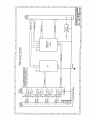
IP502 OPERATION
Connection to each serial port is provided through connector P2
(refer to Table 2.1). These pins are tied to the inputs and outputs of
EIA RS-485 line transceivers. Signals received are converted from
the required EIA RS-485 voltages signals to the TTL levels required
by the UART (Universal Asynchronous Receiver/Transmitter).
Likewise TTL signals from the UART are converted to the EIA RS485 voltages for data transmission. The UART provides the
necessary conversion from serial-to-parallel (receive) and parallel-toserial (transmit) for interfacing to the data bus. Additionally, it
provides data buffering and data formatting capabilities. A
programmable logic device is used to control the interface between
the UART, the IP bus, the line drivers and receivers, and the
IDPROM.
PRELIMINARY SERVICE PROCEDURE
Before beginning repair, be sure that all of the procedures in
Section 2, Preparation For Use, have been followed. Also, refer to
the documentation of your carrier board to verify that it is correctly
configured. Replacement of the module with one that is known to
work correctly is a good technique to isolate a faulty module.
CAUTION: POWER MUST BE TURNED OFF BEFORE
REMOVING OR INSERTING BOARDS
Acromag’s Applications Engineers can provide further technical
assistance if required. When needed, complete repair services are
also available from Acromag.
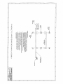
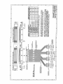
Note that the field serial interface to the carrier board provided
through connector P2 (refer to Table 2.1) is NON-ISOLATED. This
means that the field signal return and logic common have a direct
electrical connection to each other. As such, care must be taken to
avoid ground loops (see Section 2 for connection
recommendations). Ignoring this effect may cause operation errors,
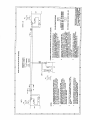
and with extreme abuse, possible circuit damage. Refer to Drawing
4501-556 for example communication wiring and grounding
connections.
- 16 -