1
SERIES IP502 INDUSTRIAL I/O PACK
QUAD EIA RS-485 SERIAL COMMUNICATION MODULE
___________________________________________________________________________________________
•
•
•
•
•
•
•
•
•
Programmable Parity Generation & Detection - Even, Odd,
or No Parity generation and detection is supported.
Line-Break Generation & Detection - provision for sending
and detecting the line break character is provided.
False Start Bit Detection - Prevents the receiver from
assembling false data characters due to low-going noise spikes
on the RxD input line.
Programmable Baud Rate - The internal baud rate generator
allows the 8MHz clock to be divided by any divisor between 1
and 2(16-1), providing support for bit rates up to 512Kbps.
Interrupt Support - Individually controlled transmit, receive,
line status, and data set interrupts may be generated. Unique
interrupt vectors may be assigned to each port. Interrupt
generation uses a priority shifting scheme based on the last
interrupt serviced, preventing the continuous interrupts of one
port from freezing out the interrupts of another port.
Socketed Termination and Bias Resistors - The network
termination and bias resistors are installed in sockets on the
board and may be easily inserted or removed where required.
Internal Diagnostic Capabilities - Loopback controls for
communication link fault isolation are included. Break, parity,
overrun, and framing error simulation is also possible.
Fail safe Receivers - The receivers employed in this model
include a fail safe feature which guarantees a high output state
when the inputs are left open or floating.
Industry Standard 16550 Family UART w/16C450 Mode The UART of this device is a member of the industry standard
16550 family of UART’s and remains software compatible.
Additionally, this device can operate in a 16C450 UART family
software compatible mode. The transmit and receive channels
are double-buffered in this mode. Hold and shift registers
eliminate the need for precise synchronization between the host
CPU and the serial data.
Cables
Model 5025-551-X (Shielded Cable), or Model 5025-550-X
(Non-Shielded Cable): A Flat 50-pin cable with female
connectors at both ends for connecting AVME9630/9660, or
other compatible carrier boards, to Model 5025-552 termination
panels. The “-X” suffix of the model number is used to indicate
the length in feet. The unshielded cable is recommended for
digital I/O, while the shielded cable is recommended for
optimum performance with precision analog I/O applications.
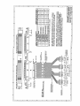
Model 5029-943 IP500 Serial Communication Cable: A 5 foot
long, flat 50-pin cable with a female connector on one end (for
connection to AVME9630/9660 or other compatible carrier
boards) and four DE-9P connectors (serial ports) on the other
end. Also used for interface with Acromag Model IP501 (RS422) & IP502 (RS-485) serial communication modules.
Model 5029-900 APC8600 High-Density Cable: A 36-inch long
interface cable that mates the high-density (25mil pitch) 50-pin
I/O connectors of the APC8600 ISA bus carrier board, to the
high-density connectors on the APC8600 Termination Panel
(described below).
Termination Panels:
Model 5025-552: A DIN-rail mountable panel that provides 50
screw terminals for universal field I/O termination. Connects to
Acromag AVME9630/9660, or other compatible carrier boards,
via flat 50-pin ribbon cable (Model 5025-550-X or 5025-551-X).
Model 5029-910 APC8600 High-Density-to-Screw-Terminal
Termination Panel: This panel converts the high-density ribboncable connectors coming from the APC8600 carrier board
(Acromag cable Model 5029-900) to screw terminals, for directwired interfaces.
INDUSTRIAL I/O PACK INTERFACE FEATURES
High density - Single-size, industry standard, IP module
footprint. Four units mounted on a carrier board provide up to
16 serial ports in a single system slot. Both VMEbus and ISA
bus (PC/AT) carriers are supported.
• Local ID - Each IP module has its own 8-bit ID PROM which
can be read via access to the "ID PROM" space.
• 8-bit I/O - Port register Read/Write is performed through 8-bit
data transfer cycles in the IP module I/O space.
• High Speed - Access times for all data transfer cycles are
described in terms of "wait" states - 2 wait states are required
for reading and writing channel data and for interrupt select
cycles, 1 wait state for reading the ID PROM (see
Specifications section for detailed information).
•
Transition Module:
Model TRANS-GP: This module repeats field I/O connections
of IP modules A through D for rear exit from a VMEbus card
cage. It is available for use in card cages which provide rear exit
for I/O connections via transition modules (transition modules
can only be used in card cages specifically designed for them).
It is a double-height (6U), single-slot module with front panel
hardware adhering to the VMEbus mechanical dimensions,
except for shorter printed circuit board depth. It connects to
Acromag Termination Panel 5025-552 from the rear of the card
cage, and to AVME9630/9660 boards within the card cage, via
flat 50-pin ribbon cable (cable Model 5025-550-X or 5025-551X).
INDUSTRIAL I/O PACK SOFTWARE LIBRARY
SIGNAL INTERFACE PRODUCTS
(See Appendix for more information on compatible products)
Acromag provides an Industrial I/O Pack Software Library
diskette (Model IPSW-LIB-M03, MSDOS format) to simplify
communication with the board. Example software functions are
provided for both VMEbus and ISA bus (PC/AT) applications. All
functions are written in the “C” programming language and can be
linked to your application. For more details, refer to the
“README.TXT” file in the root directory on the diskette and the
“INFO502.TXT” file in the appropriate “IP502” subdirectory off of
“\VMEIP” or “\PCIP”, according to your carrier.
This IP module will mate directly to any industry standard IP
carrier board (including Acromag AVME9630/9660 3U/6U nonintelligent VMEbus carrier boards). Additionally, Acromag’s
APC8600 ISA bus (PC/AT) carrier board is also supported. A wide
range of other Acromag IP modules are also available to serve your
signal conditioning and interface needs.
The following cables and termination panels are also available.
Consult your carrier board documentation for the correct interface
product part numbers to ensure compatibility with your carrier board.
-3-