1
Adam Equipment
PMB Moisture Analyzer
(P.N. 9618, Revision E2, April 2010)
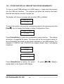
Model No
Serial No
E.G.Kantawalla Pvt Ltd
2|Page
www.egkantawalla.com
1.0
1.0
2.0
3.0
CONTENTS
CONTENTS ........................................................................................................................ 3
INTRODUCTION................................................................................................................. 5
SET UP ............................................................................................................................... 6
3.1
3.2
3.3
3.4
3.5
3.6
4.0
UNPACKING AND SETTING UP YOUR ANALYZER .................................................................................... 6
ASSEMBLING THE ANALYZER .................................................................................................................... 7
LEVELLING THE ANALYZER........................................................................................................................ 8
WARM-UP TIME ............................................................................................................................................ 8
LOCATING AND PROTECTING YOUR ANALYZER ..................................................................................... 9
SAFETY ....................................................................................................................................................... 10
DISPLAY and KEYPAD.................................................................................................... 13
4.1
5.0
NUMERIC ENTRY METHOD ....................................................................................................................... 15
REAR PANEL INTERFACES............................................................................................ 16
5.1
5.2
5.2.1
5.3
6.1
6.1.1
6.1.2
6.2
6.3
6.4
6.5
6.6
7.0
8.0
RUNNING A TEST ............................................................................................................ 33
PRINT AND STORE RESULTS ........................................................................................ 37
8.1
8.2
8.3
8.4
9.0
10.0
POWER ....................................................................................................................................................... 16
DATA INTERFACES .................................................................................................................................... 16
FILES ON A USB MEMORY DEVICE............................................................................................. 17
SECURITY LOCK ........................................................................................................................................ 18
SETUP OF METHOD ................................................................................................................................... 18
MANUALLY SETTING TEST PROCEDURES ................................................................................. 21
PRINT CURRENT SETTINGS......................................................................................................... 26
STORE TEST SETTINGS ........................................................................................................................... 27
RECALL TEST SETTINGS .......................................................................................................................... 28
DELETE TEST SETTINGS .......................................................................................................................... 29
REVIEW TEST SETTINGS ......................................................................................................................... 29
STORE and RECALLING TEST SETTINGS FROM USB MEMORY ........................................................... 30
PRINTING FINAL TEST RESULTS.............................................................................................................. 37
STORING TEST RESULTS ......................................................................................................................... 37
RECALLING TEST RESULTS ................................................................................................................... 38
DELETING TEST RESULTS...................................................................................................................... 38
STORING RESULTS IN USB MEMORY .......................................................................... 40
ANALYZER MENUS ......................................................................................................... 42
10.1
SUPERVISOR MENUS ................................................................................................................................ 42
10.1.1
SERIAL INTERFACE PARAMETERS ............................................................................................. 44
10.1.2
SETUP PARAMETERS ................................................................................................................... 45
10.1.3
CALIBRATION ................................................................................................................................. 46
10.1.3.1
MASS CALIBRATION..................................................................................................................... 47
10.1.3.2
TEMPERATURE CALIBRATION ..................................................................................................... 48
10.1.3.3
CALIBRATION REPORT ................................................................................................................. 50
10.1.4
PASSCODES .................................................................................................................................. 52
10.1.4.1
FORGOTTEN PASSCODES ........................................................................................................... 52
10.2
STORE AND RECALL PMB SETTING FROM USB MEMORY................................................................... 53
11.0
SERIAL INTERFACE ....................................................................................................... 56
11.1
11.2
11.3
11.4
11.5
11.5.1
11.5.2
11.5.3
11.5.4
11.6
12.0
RS-232 HARDWARE ................................................................................................................................... 56
USB SERIAL HARDWARE .......................................................................................................................... 56
INPUT COMMANDS .................................................................................................................................... 57
PRINTING RESULTS................................................................................................................................... 57
ANALYZER CONFIGURATION THROUGH THE SERIAL INTERFACE...................................................... 60
TEST PARAMETERS ...................................................................................................................... 60
PMB SETUP PARAMETERS........................................................................................................... 61
ANALYZER RECALL PARAMETERS ............................................................................................. 62
REQUEST VALUES OF PARAMETERS ........................................................................................ 62
CONTINUOUS OUTPUT.............................................................................................................................. 63
SPECIFICATIONS & FEATURES ..................................................................................... 64
E.G.Kantawalla Pvt Ltd
3|Page
www.egkantawalla.com
13.0
14.0
15.0
16.0
MENU STRUCTURE......................................................................................................... 66
SAMPLE PREPARATION................................................................................................. 72
GUIDANCE NOTES .......................................................................................................... 74
WARRANTY STATEMENT .............................................................................................. 76
E.G.Kantawalla Pvt Ltd
4|Page
www.egkantawalla.com
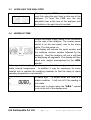
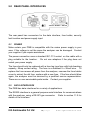
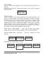
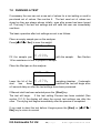
2.0 INTRODUCTION
Thank you for selecting the PMB Moisture Analyzer.
This Instruction Manual will familiarize you with the installation, accessories,
trouble-shooting, after sales service information, general maintenance of the
analyzer, etc. and will guide you through the various applications.
Please read this Manual thoroughly before starting the operation. If you need
any clarifications, feel free to contact your supplier or Adam Equipment.
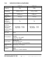
PRODUCT OVERVIEW
The PMB Moisture analyzers are ideal for laboratory moisture determination.
FEATURES:
• Large easy to read LCD display with
backlight
• Bi-directional RS-232 interface and
USB interface.
• USB Host connection for memory
device
• Can be configured to print a GLP
Compliant report after each calibration
to include the time, date, analyzer
number and a verification of the
calibration
• 400 watt Halogen Heater
• Rapid heat Function
• Capacity tracker
• Date and time
• Easy to use, sealed keypad
• Password protection
• Security locking point
• Multiple languages for display and
printing
E.G.Kantawalla Pvt Ltd
5|Page
www.egkantawalla.com
3.0 SET UP
3.1
UNPACKING AND SETTING UP YOUR ANALYZER
Remove the PMB from the packing by carefully lifting it out of the box.
Inside the box you will find everything needed to start using the analyzer
AC power cable
Pan Support
Stainless Steel Lower Chamber Insert
Sample Pan Lifter
Sample Pans (x10)
Spare Fuse 5A, Time Lag, High capacity
This User Manual
For PMB supplied from the USA only:
RS-232 Interface Cable for use with a PC
USB to PC cable
USB driver software on CD
IMPORTANT:
Before applying power make sure the PMB is configured for the power in
your area. The analyzer will have a label on the rear panel showing the
voltage required. 115VAC (±10%) or 230VAC (±10%). If the label does not
match your power do not attempt to use the analyzer, damage to the PMB
could result.
The PMB should be positioned to allow easy access to the mains power
connection. on the rear panel. Ensure the power cable is fully engaged to
ensure safe operation.
E.G.Kantawalla Pvt Ltd
6|Page
www.egkantawalla.com
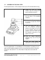
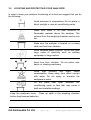
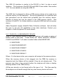
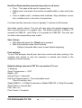
3.2
ASSEMBLING THE ANALYZER
For best performance, let the analyzer warm up for 30 minutes before using.
Locate the PMB on a solid
surface, free from vibration with
good ventilation around it.
Place the lower reflector (1)
into the base of the weighing
chamber
Gently place the pan support
(2) into the access hole. Rotate
to position.
Place the sample pan lifter (3)
into the weighing chamber,
rotate so the tangs on the lifter
do not interfere with the pan
supports and the handle exits
the chamber using one of the
gaps in the cover.
Place an empty aluminium
weighing tray (4) on the pan
support
Level the PMB using the
adjustable feet and spirit level
For some applications it is desirable to run the analyzer in a dummy run to
warm up the weighing chamber and the surrounding area before doing the
actual test. See section 14 for other ideas to help ensure accurate test
results.
E.G.Kantawalla Pvt Ltd
7|Page
www.egkantawalla.com
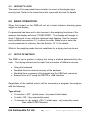
3.3
LEVELLING THE ANALYZER
After placing the PMB in a suitable location,
level it by using the spirit level on the rear of the
analyzer. To level the PMB turn the two
adjustable feet at the rear of the analyzer until
the bubble in the spirit level is centred.
3.4
WARM-UP TIME
Attach the power supply cable to the connector
on the rear of the analyzer. The master power
switch is on the rear panel, next to the mains
cable. Turn the power on.
The display will indicate the serial number and
the software revision number followed by the
capacity. Next the analyzer will run a self-test
by displaying all segments. The display will then
show zero weight accompanied by the 0
symbol.
Before you start weighing, you have to wait for the analyzer to achieve a
stable internal temperature. In addition it may be necessary for some
material test to preheat the weighing chamber so that the delay to reach
operating temperature is minimised.
A stable sign ~ is shown when the PMB is in
stable condition. It will turn off if the reading is
not stable.
Exact zero is shown when the “0 “ symbol
is on to the left of the display area.
E.G.Kantawalla Pvt Ltd
8|Page
www.egkantawalla.com
3.5
LOCATING AND PROTECTING YOUR ANALYZER
In order to keep your analyzer functioning at its best we suggest that you do
the following:
Avoid extremes of temperature. Do not place in
direct sunlight or near air conditioning vents.
Make sure there is no heat sensitive or
flammable material above the analyzer. The
exhaust from the weighing chamber can be very
hot.
Make sure the analyzer is located on a strong
table and free from vibration.
Avoid unstable power sources. Do not use near
large users of electricity such as welding
equipment or large motors.
Keep free from vibration. Do not place near
heavy or vibrating machinery.
Avoid high humidity that might cause
condensation. Keep away from direct contact
with water. Do not spray or immerse the
analyzers in water.
Do not place near open windows, airconditioning vents or fans that may cause a
draft and unstable readings.
Keep the analyzers clean. Clean up spills in the weighing chamber
before they become baked on.
E.G.Kantawalla Pvt Ltd
9|Page
www.egkantawalla.com
3.6
SAFETY
This PMB Moisture Analyzer complies with the European Council Directives
and international standards for electromagnetic compatibility, and safety
requirements.
Improper use or handling can result in damage or injury.
To prevent damage to the equipment, read these operating instructions
thoroughly. Keep these instructions in a safe place.
For safe and dependable operation please follow these instructions.
• The Moisture Analyzer is used for determination of the moisture in
samples. Do not use it for any other purpose. Improper use is dangerous
and can cause injury or damage to other property.
• The Moisture Analyzer must be operated as described in this manual. The
environment must be controlled so that hazardous materials or conditions
are not present.
• The Moisture Analyzer must be operated only by trained personnel who
are familiar with the properties of the samples used and with the operation
of the instrument. Do not leave the analyzer unattended when running a
test.
• Make sure before getting started that the voltage printed on the rear panel
is identical to your local voltage.
• Your Moisture Analyzer is supplied with a 3-pin power cable with a
grounding conductor. Use cables that meet the safety standards for your
location and include the earth ground conductor.
• DO NOT disconnect the earth ground connection.
• The mains cable should not touch the enclosure where it can be heated
during the test.
• Remove the power cable if the Moisture Analyzer is serviced.
E.G.Kantawalla Pvt Ltd
10 | P a g e
www.egkantawalla.com
• Protect the Moisture Analyzer from external liquids. Clean any spills
immediately.
• If there are any visible damage to the Moisture Analyzer or the power
cable, Stop using the instrument immediately. Unplug the power and
isolate the analyzer. Do not use until the faults have been repaired.
• All repairs must be done by a trained technician. There are no user
serviceable parts in the enclosure.
• Contact Adam Equipment or your dealer for assistance.
HOT SURFACES
• During test the cover of the heating chamber can become very hot,
especially near the top vent. Keep all material away from the vent area.
Do not touch hot surfaces.
• leave 20 cm (about 8 inches) around the moisture analyzer and 1 m (3 ft.)
above.
• Samples will be hot after a test. Do not use bare fingers to pick up any
samples pans or touch the materials. The internal surfaces of the
weighing chamber may be hot for some time after a test.
MATERIALS
• The PMB Moisture Analyzer is not suitable for all materials. During the
drying process samples will be heated to high temperatures. Materials that
are flammable or explosive should not be tested.
E.G.Kantawalla Pvt Ltd
11 | P a g e
www.egkantawalla.com
• Materials that emit toxic, caustic or noxious fumes should only be tested in
suitable fume hoods or with other ventilation.
• Materials that will have a film on the surface during drying may cause high
internal pressures to be present. These materials should not be tested
using this method.
• Materials that emit aggressive or corrosive fumes (such as acids) should
be tested using small quantities of material in an area with good
ventilation.
• See Section 14 for further information on sample preparation.
The user shall be liable and responsible for any damage that arises in
connection with this moisture analyzer.
E.G.Kantawalla Pvt Ltd
12 | P a g e
www.egkantawalla.com
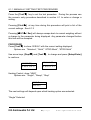
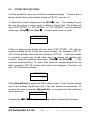
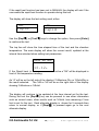
4.0 DISPLAY AND KEYPAD
The LCD has unique symbols to indicate the following:
0
Zero
Stable
Net
Net weight
A bar graph indicating the proportion of
the analyzer capacity being used by the
weight on the pan
Note: Some symbols shown on the display are not used in the analyzers.
During the moisture test the main display will show the percent moisture. It
can be switched to other values using the [Dspl/
] key. For example
current mass.
The secondary display will show the elapsed time and temperature during a
test.
Typical Displays that would be used are:
Weighing:
Showing no weight on the pan,
stable and at zero point.
E.G.Kantawalla Pvt Ltd
13 | P a g e
www.egkantawalla.com
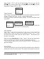
During a typical Moisture test:
Showing a test in progress for
13:25,
with
a
current
temperature of 123ºC and
20.05% moisture, the test is still
running.
The keypad has second function keys to allow a selected menu item or value
to be incremented or changed. Right/left shift to change the active digit and
up/down to increment or decrement a value.
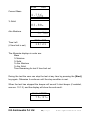
The keypad has the following keys to operate the analyzer.
Keys
Primary function
Secondary function
To turn the analyzer to ON or
Standby
-
[
0/T
/ Esc]
A combined zero and tare function
To escape from setup functions
and modes
[Start]
To begin the moisture test after all
settings and sample preparation
has been completed. During a test,
used to stop the test.
Selects moisture test parameters
such as temperature, method,
results.
-
[Test/
]
E.G.Kantawalla Pvt Ltd
14 | P a g e
-Scrolls through menu options
To decrement or change a
displayed value
www.egkantawalla.com
[PST/
]
Store or Recall pre-stored test
parameters.
[Print/
]
Instructs the analyzer to print data
[Dspl/
]
Changes the display to read other
data during a moisture test.
To increase or change a
displayed value or scroll
through options forward
Enters the Setup parameters
(Supervisor Menus)
Enters a function or saves a
value while manually entering
unit weight or check weighing
limits
[Setup/Enter]
To advance a flashing digit by
one position to the right.
To go back by one step during
setup functions
To advance a flashing digit by
one position to the left
4.1 NUMERIC ENTRY METHOD
To set a value when required, use the keys as given below- [Dspl/
] and [Test/
] keys to increase or decrease the flashing digit
- [Print/
] and [PST/
] keys to advance or move back the digit
- [Setup/Enter] key to accept the value
E.G.Kantawalla Pvt Ltd
15 | P a g e
www.egkantawalla.com
5.0 REAR PANEL INTERFACES
The rear panel has connectors for the data interface, fuse holder, security
lock location and power supply input.
5.1
POWER
Make certain your PMB is compatible with the mains power supply in your
area. If the voltage is not the same the analyzer can be damaged. Contact
your supplier if you require assistance.
The power connection uses a standard IEC C13 socket on the cable with a
plug suitable for the location. Do not use adaptors if the plug does not
match your power supply.
The fuse should only be replaced with a time lag type fuse with high breaking
capacity, 5Amp current rating. The fuse is a standard 5 x 20mm size. To
replace the fuse remove all power from the analyzer, unscrew the fuse holder
cover to extract the old fuse, replace with a new fuse. If the fuse should blow
again, the analyzer must be serviced by a qualified service representative.
There are no user serviceable parts inside. Contact your supplier.
5.2
DATA INTERFACES
The PMB has data interfaces for a variety of applications.
The RS232 interface is a general purpose serial interface for communications
with the analyzer, using a DE-9P type connector. Refer to section 11.0 for
details of the interface.
E.G.Kantawalla Pvt Ltd
16 | P a g e
www.egkantawalla.com
The USB I/O interface is similar to the RS-232 in that it is also a serial
interface. The functions of the RS-232 and USB I/O are similar. See section
11.0 for more details on using the USB I/O.
The USB Host is designed to allow a USB memory device to be used as an
external memory for the analyzers. The set-up parameters for operation and
test procedures can be stored and up-loaded from the memory device.
Results of drying test can be stored in the USB memory device. See
sections 6.5 and 9.0 for further details on using the USB Host with a memory
device.
Adam Equipment supply AdamDU Data Collection software that will allow
the user to use the full capabilities of the data interfaces. Contact your
supplier or Adam Equipment for more details.
5.2.1 FILES ON A USB MEMORY DEVICE
When a USB memory device is used the analyzer will create a series of
folders used to store files. These folders are called, REPORT, PRESET,
CONFIG and RESULT, all under a master folder called MOISTURE .
X:\ MOISTURE
X:\ MOISTURE\REPORT
X:\ MOISTURE \PRESET
X:\ MOISTURE \CONFIG
X:\ MOISTURE \RESULT
Where X is the device letter your computer will assign to the memory device.
When the memory device is first plugged into the PMB the memory is
inspected and the folders will be created if they do not already exist. This
process may take a few seconds before the analyzer will show a display
allowing access to the USB memory.
All files are stored in a text format with a file type of .txt. The files used by
the analyzer are all small enough that any size memory device will work.
E.G.Kantawalla Pvt Ltd
17 | P a g e
www.egkantawalla.com
5.3
SECURITY LOCK
The centre of the rear panel has a location to mount a Kensington type
security lock. Refer to the instructions that come with the lock for details.
6.0 BASIC OPERATION
When first turned on the PMB will act as a basic balance showing grams
weight on the display.
If a passcode has been set to limit access to the weighing functions of the
analyzer the display will show “PASSCODES”. The display will change to
show 7 digits set to zero with the rightmost digit flashing. Use the numeric
entry method (see section 4.1) to enter the code. Make sure to enter the
correct passcode to continue. See the Section 10.1.4 for details.
While in the weighing mode the test conditions for a drying test can be set.
6.1
SETUP OF METHOD
The PMB is set to perform a drying test using a method determined by the
user. The drying method can be input from a number of different sources.
•
•
•
•
Using the keyboard
Recalled from the internal memory of the analyzer
Recalled from a memory stick plugged into the USB host connector
Entered from a PC using the RS232 or USB interface.
Regardless of the method used it will be necessary to program the analyzer
with the following:
Type of test:
• % moisture =100 * ((initial mass - dry mass)/initial mass)
• % solid =100 * (dry mass/initial mass)
• % moisture vs. dry weight =100 * ((initial mass - dry mass)/dry mass)
Also called ATRO Moisture
E.G.Kantawalla Pvt Ltd
18 | P a g e
www.egkantawalla.com
• % solid vs. dry weight = 100 * (Initial mass/dry mass)
Also called ATRO Solid
ATRO Moisture or Solid test are special applications specific to some
industries. %Moisture and %Solid are the more common calculations.
Heat Control
• Single temperature, heat to a set temperature.
• Ramp to temperature, Ramp to final temperature in a user set time.
• Step temperature, heat to Temp 1, for X minutes, then temp 2 for X
minutes, then Temp 3 for X minutes. A maximum of 3 steps can be
used.
Set temperatures as required for these options. 50-160ºC.
For Ramp set the time to final temperature.
For Step set the temperature and the time at each step.
Interval
Set the time interval at which the results are computed and printed. Range is
1 to 99 seconds.
Rapid heat
Set the rapid heat function to be on, off or under user control.
Rapid heat will cause the target temperature to be 145% (or 160ºC, which
ever is less) of the value set for Single or the first Step for a time of 3
minutes. For example is the Single temperature is 105ºC, the rapid heat will
heat to 105X 1.45= 152ºC for 3 minutes then maintain 105º after that time.
If set to Rapid = Off
The rapid heat function is disabled.
Rapid =On
The rapid heat function will occur every time a test is started.
Rapid = MANUAL
When a test is started Manually, the user will be asked if Rapid heat should
be used or not.
E.G.Kantawalla Pvt Ltd
19 | P a g e
www.egkantawalla.com
End Point Determination (manual stop active in all tests)
• Time, Test ends at the end of a preset time.
• Stable result, test ends if the results are stable within a value set by the
user.
• Time or stable result, combines both methods. Stop whichever occurs
first, a stable result or the end of a preset time.
For timed test the user sets a time of typically 5 minutes to 99 minutes
Set stable results criteria. The test will stop when the weight changes less
than a preset amount in a preset time. The default setting is 0.002g in 15
seconds for PMB 53, and 0.02g in 15 seconds for PMB 202. The user can
set other values depending upon model.
Start Criteria
• Start Manually when the [Start] key is pressed
• Start Automatically when cover lowered.
Delays 5 seconds after cover is down before beginning.
Print settings:
To set if the analyzer should print and store results and when printing if the
compete test results or only the summary is printed and stored in the
analyzers internal memory.
Default settings (stored in PST 00, see section 6.3) are:
% Moisture
Single Temperature = 110ºC
Rapid = Off
Interval Time = 5 seconds
End Point Determination = Time and stable result
Time 60 minutes, and
Stable PMB 53 = 0.002g/15 seconds or Stable PMB 202 = 0.02g/15 seconds
Start Criteria = manual start.
Print Test = on
Print Format = Complete
E.G.Kantawalla Pvt Ltd
20 | P a g e
www.egkantawalla.com
6.1.1 MANUALLY SETTING TEST PROCEDURES
Press the [Test/
] key to set the test procedure. During the process use
the numeric entry procedure described in section 4.1 to enter or change a
setting.
Pressing [Print/
] at any time during this procedure will print a list of the
current settings. See 6.1.2
Pressing [
0/T
/ Esc] will always escape back to normal weighing without
a change to the parameter being displayed. Any parameter changed before
this time will be accepted.
PROCEDURE
Press [Test/
] to show “rESULt” with the current setting displayed,
Options are “Moisture”, “Solid”, “ATRO Moist”, “ATRO Solid”
Use arrow keys, [Dspl/
] and [Test/
], to change and press [Setup/Enter]
to continue.
MOISTURE
ATRO MOIST
result
result
Heating Control, show “HEAt”
Options are: “Single”, “Ramp”, “Step”
SINGLE
Keat
The next settings will depend upon which heating option was selected:
“Single” Selected
E.G.Kantawalla Pvt Ltd
21 | P a g e
www.egkantawalla.com
Show “Single” “123 C” with the left digit flashing. The user can use the
[PST/
] key to select another digit or the [Dspl/
] and [Test/
] to set the
temperature, Range is 050 C to 160 C
SINGLE
ºC
123
“Ramp” Selected
Show “Ramp” the temperature as above for setting the temperature and then
change to “Ramp Time” and “ XX:XX ”, minutes and seconds.
Use the arrow keys to select the digit to change. The user can select a time
up to 99:59.
RAMP
ºC
RAMP TIME
10:00
123
RAMP TIME
06:00
The ramp time should be set long enough to allow the
heater to warm the sample gently.
“Step” Selected
Show “Step 1” and set the temperature of step one as for the single heat
settings above. When the value is set the display will show “Time 1” to set
the time the first step is held. Enter the value as above. The minimum time
for step 1 is 3 minutes.
When set press [Setup/Enter] to show “Step 2” and set this temperature
and time and then go to “Step 3” and set this temperature and time.
If only 2 steps are required set the time for step 3 to 00:00. The analyzer will
ignore this setting.
Interval Setting
The next setting will be to set the time interval the analyzer uses to determine
results and to print the current result. The analyzer will compute the percent
E.G.Kantawalla Pvt Ltd
22 | P a g e
www.egkantawalla.com
moisture or solid at the time interval desired. The new result will be displayed
and printed as described below.
Display “Interval” “Sec XX” The user can change the value using the arrow
keys. Range is 01 to 99 Seconds. Typical results will be computed every 515 seconds.
INTERVAL
se[10
The next setting is the operation of the Rapid heat Function.
Display will show “Rapid”
OFF
rapid
USER
ON
rapid
rapid
Options are to set Rapid heat to Off, On or User selectable.
The Rapid heat function is only active for single or step heating. For ramp
heating it is disabled.
The next setting is the End Point Determination or Stop Condition.
Display will show “STOP”
TIME
St0p
TIME/STAB
St0p
Options are “Time”, “Stable” or “Time/Stab”
The next steps will depend upon the option selected.
E.G.Kantawalla Pvt Ltd
23 | P a g e
www.egkantawalla.com
“Time” selected
Enter the time the test should run. The test will stop when this time is
reached.
Display will show “Min XX”. This sets the minutes to run a test. The range is
04 to 99 minutes.
STOP TIME
Min 30
“Stable” selected
Enter the conditions to be used to determine if the results are stable. The
amount of weight change to be used to determine if the test is finished,
followed by the time to be used for the weight to change. For example 0.006g
in 15 seconds would be a typical setting. Longer times or smaller weight
changes could be used to ensure better stability or shorter times or larger
weight changes to ensure a faster determination. For example 0.006g in 5
seconds will end a test quicker (but possibly less accurately ) than 0.002g in
15 seconds. The user sets the weight first, then the time.
Display shows “ STAB RANGE” “
XXX”. Set the range for the weight
change. Set from 0.001 to 0.099 for PMB 53 or 0.01 to 0.99 for PMB 202.
Then the display shows “ Stop Time”
seconds.
“ Sec XX”.
Range is 01 to 99
STABLE
STAB RANGE
STAB TIME
St0p
02
sec15
Time/Stable will combine these 2 settings.
TIME/ STAB
STOP TIME
St0p
min
30
E.G.Kantawalla Pvt Ltd
STOP RANGE
02
24 | P a g e
STOP TIME
sec15
www.egkantawalla.com
Start Method
The last setting is the Start method. The analyzer will either start a test
automatically whenever the cover is lowered (after a 5 second delay to allow
stability), or manually when the [Start] key is pressed.
Display will show “START”
Options are “Manual” or “Auto”
MANUAL
start
Print Control
To allow the analyzer to print the results during the test. If the print is set to
ON the analyzer will also store the results to memory using the file name
given by the user. See Section 7.0
Display will show
PRINT TEST
0n
Options are “On” or “Off”
The display then changes to the format of the print test.
FORMAT
FORMAT
C0MP
SUMM
Options are “Complete ” or “Summary ” test results. See section 11.3
After setting the last parameter press [
0/T
/ Esc] to return to normal
weighing and ready to begin a new test.
E.G.Kantawalla Pvt Ltd
25 | P a g e
www.egkantawalla.com
6.1.2 PRINT CURRENT SETTINGS
When setting the test parameters the [Print/
] key will cause the current
parameters to be printed as shown below. However if the display is awaiting
a numeric entry the [Print/
] key will move the flashing digit to the left.
For example (English language version shown) :
CURRENT TEST SETTINGS
DATE: 08/01/2009
TIME:
14:44:49
SER NO:AE00001234
USER NO:1234567
Preset: PST 01
ABCD-01234
Result %MOISTURE
Heating:Ramp
112 C
27:00
Rapid
Manual
Interval: 05 Sec
Stop:
TIME/STABLE
60 Min
0.002 g
15 Sec
Start:
MANUAL
E.G.Kantawalla Pvt Ltd
From the Real Time Clock
Analyzer Serial number
User ID number
If Preset test is used, blank if not
from a preset test.
Current test settings for heating
Printing interval
Stop Criteria
Start Criteria
26 | P a g e
www.egkantawalla.com
6.2
STORE TEST SETTINGS
It will be possible to store up to 49 test procedures/settings. There is also a
factory default that is permanently stored as PST 00. see sec. 6.1
To Store the current settings press the [PST/
] key. The display will give
the user the option to store, recall or delete a Preset Test. The display will
show “PST STORE” or “PST RECALL” or “PST DELETE”. Use the up/down
arrow keys, [Dspl/
] and [Test/
], to select either store or recall.
PST STORE
If Store is selected the display will then show “PST STORE XX” with the
number showing the ID for the next empty location. For example if PST 01,
02, & 03 are already stored the next number is PST 04. If the user wishes
to overwrite a previously stored value they can change the number and
continue. Using the up/down arrow keys, [Dspl/
] and [Test/
].
If the
user has stored positions 1,2, and 4 then when this process begins the first
blank location is PST 03, so that is the value to be displayed. Then the next
time PST 05 would be shown.
PST STORE
05
Press [Setup/Enter] to select the PST number shown. If this number already
has a test method stored then ask if the test should be overwritten. To
continue the user must press [Setup/Enter] to overwrite the old results and
store new ones.
OVERWRITE?
Pressing the [
0/T
/ Esc] key will escape without clearing the old result.
E.G.Kantawalla Pvt Ltd
27 | P a g e
www.egkantawalla.com
When storing a test procedure the user has the option of adding a text or
numeric name to the test. The top display will show “PST NAME” then show
“- - - - - - - - - “ . To enter a name, use the [Dspl/
] or [Test/
] keys to
cycle through numbers and letters. Use the [PST/
] or [Print/
] key to
move the flashing digit to the left or right.
—./ 0123456789ABCDEFGHIJKLMNOPQRSTUVWXYZ
Up to 10 characters can be used to describe the test. Press [Setup/Enter]
at any time to finish the description. If no name is added the field will be
shown as blanks when the name is shown during the recalling process.
PST NAME
6.3
BREAD-4
RECALL TEST SETTINGS
Recalling the test settings can be done by selecting “PST RECALL” then
scrolling through the stored settings using the [Dspl/
] or [Test/
] keys to
find the desired settings and then pressing the [Setup/Enter] key to recall
them. When the PST XX number has been selected the name given to the
test will be displayed
If PST 00 is selected the default test settings are recalled. These can never
be cleared or overwritten. If a test is not stored it is not displayed, i.e. If only 3
tests are stored then only those 3 plus the default are seen when recalling
the test settings.
E.G.Kantawalla Pvt Ltd
28 | P a g e
www.egkantawalla.com
BREAD-3
PST 07
Press the [Setup/Enter] key to recall PST 07.
The display will show:
RECALL OK
The analyzer will then return to normal.
6.4
DELETE TEST SETTINGS
To delete any the test setting select “PST DELETE” then scrolling through
the stored settings using the [Dspl/
] or [Test/
] arrow keys to find the
desired settings and then pressing the [Setup/Enter] key to delete it.
The display will then show the next test setting stored or if the memory is
empty a message will be shown. Press [
0/T
/ Esc] to return to normal.
6.5
REVIEW TEST SETTINGS
To review the current settings press the [Test/
] key then advance through
the settings pressing the [Setup/Enter] key at each option to retain the
current value. If any setting needs to be changed it can be modified as
described in section 6.1.
At the beginning of a test the display will preview the current settings if the
user parameter to allow the preview is enabled. See section 10.1.2.
If you need to abort the test before it begins press the [Start] or [
0/T
/
Esc] key to return to normal.
E.G.Kantawalla Pvt Ltd
29 | P a g e
www.egkantawalla.com
6.6
STORE AND RECALLING TEST SETTINGS FROM USB MEMORY
To store or recall test settings stored on a USB memory device, simply plug
the device into the USB hub interface. The analyzer will detect the memory
has been inserted and display a screen to guide you.
The display will show a message showing the USB device is inserted:
CONFIG LD
USB
To select the option
of storing all of the test settings
stored in the analyzer memory to the USB memory device press the [Dspl/
]
key to change the menu option to select Preset Store, “PST ST”.
PST ST
USB
Press [Setup/Enter] to enter the test saving function.
Once the file has been saved the display will show
SUCCESS
USB
For 2 seconds then return to the USB display.
PST ST
USB
To recall any stored test procedure press the [Dspl/
] key to show the test
load screen.
PST LD
USB
E.G.Kantawalla Pvt Ltd
30 | P a g e
www.egkantawalla.com
Press the [Setup/Enter] key to enter the test load function. The display will
show the file name of the first test file found.
PST 01
PSt
To load this file press the [Setup/Enter] key again. Or to choose a different
file press the [Dspl/
] key to advance through the other files available,
pressing the [Setup/Enter] key when the desired file is shown.
PST 06
PST
After loading the file the display will show a Success message and return to
the USB screen. To continue, the USB device should be removed. The
analyzer will return to normal weighing automatically. Or press the [
0/T
/
Esc] key to escape back to normal weighing.
To store or recall other test files plug the USB memory device back into the
analyzer.
The test files contain data to set the parameters of the test procedures in a
text file. All files will be in English regardless of the language selected for the
display. A typical test file will appear as:
Result=0;
Heat=1;
Ramp Temp=112;
Ramp Time=27:00;
Interval Time=05;
Stop mode=2;
Stop time=60;
Stable Range=0.002;
Stable Time=15;
Start mode=0;
Name=ABCD-0123
Rapid=1
savepos=01;
E.G.Kantawalla Pvt Ltd
31 | P a g e
www.egkantawalla.com
The meaning of the text in the file is given below. Different test settings will create a file
with different information. Not all settings are printed if they are not used by the test
program.
Text message
Description
Range of Values
Result=1;
Calculation of results
Heat=1;
Single Temp=100;
Ramp Temp=100;
Heating profile to be used
Temperature for single heat
setting
Temperature for first heat of a
step profile
Time for the first heat of a step
profile
nd
Temperature for 2 heat of a step
profile
nd
Time for the 2 heat of a step
profile
rd
Temperature for 3 heat of a step
profile
Time for the 3rd heat of a step
profile
Final temperature of a ramp profile
0=%M, 1=%S, 2=%Atro_M,
3=%Atro_S
0=Single, 1=Step, 2=Ramp
50C to 160C
Ramp Time=30:00;
Time to reach final temperature
Time 02:00 to 99:00
Interval Time=20;
Time period used to print interim
test results
Rapid heat function setting,
Stop mode for drying test
5 sec to 99 sec
Step temp1=050;
Step Time1=30:00;
Step temp2=080;
Step Time2=30:00;
Step temp3=050;
Step Time3=30:00;
Rapid=0;
Stop mode=0;
Stop time=10;
Stable Range=0.002;
Stable Time=10;
Start mode=0;
Name=ABCDE12345;
savepos=01;
Time to stop test
Weight the analyzers uses to
determine if the results are stable
at the end of test.
Time used to compare weight
during a test to determine if the
results are stable at the end of
test.
Start test manually or when the
cover is closed
Name assigned by the user if the
test results are to be stored
Memory location the results are
stored in.
E.G.Kantawalla Pvt Ltd
32 | P a g e
50C to 160C,
000C is off
Time 02:00 to 99:00
50C to 160C,
000C is off
Time 02:00 to 99:00
50C to 160C,
000C is off
Time 02:00 to 99:00
50C to 160C
0= Off, 1= On, 2= User
0=Time, 1=Stable, 2=Stab and
Time
time = 03 to 99 min
Set from 0.001 to 0.099 for PMB
53 or 0.01 to 0.99 for PMB 202
05 sec to 99 sec
0=Manual 1=Auto
Exactly 10 characters of alphanumeric characters, plus . / 01 to 49
www.egkantawalla.com
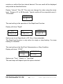
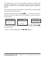
7.0 RUNNING A TEST
If necessary the user can set a new set of values for a test setting or recall a
pre-stored set of values. See section 6. The last used set of values are
stored so they are always shown initially, even after power has been turned
off. That way if the last test settings are still valid the user can immediately
use them.
The basic operation after test settings are set is as follows:
Place an empty sample pan on the analyzer.
Press [
0/T
/ Esc] to zero the weight.
MASS
23ºC
0.000g
Fill the sample pan
with the sample.
14 for assistance in how to prepare a sample.
See Section
Place the filled pan on the analyzer.
MASS
23ºC
5.670
Lower the lid of the
weighing chamber, if automatic
g
start
has
been
selected the test will begin after
a 5 second delay or after the test settings have been previewed.
If Manual start has been selected press the [Start] key.
The test will begin.
If the test setting Preview has been enabled (See
section 10.1.2) the display will show the current test settings one after the
other. The drying test begins immediately after the preview is completed. ..
If you need to abort the test before it begins press the [Start] or [
0/T
/
Esc] key to return to normal.
E.G.Kantawalla Pvt Ltd
33 | P a g e
www.egkantawalla.com
If the rapid heat function has been set to MANUAL the display will ask if the
user wants the rapid heat function to operate during this test.
The display will show the last setting used, either:
OFF
ON
rapid
rapid
Use the [Dspl/
] or [Test/
] keys to change the option, then press [Enter]
to continue the test.
The top line will show the time elapsed time of the test and the chamber
temperature. The main display will show the current result, updated at the
interval time selected when setting test parameters.
03:45 RA 100ºC
16.12%
If the Rapid heat is
front of the temperature reading.
active a “RA” will be displayed in
An “A” will be on the left side of the display if %Moisture /Dry or %Solid/Dry is
the result selected. The %M or %S will be on the right side of the display
showing %Moisture or %Solid.
The display will continue to be updated at the time interval set for the test.
During the test the [Dspl/
] key can be pressed to see other information
such as current mass, other results such as %Solid, time remaining if time
limit is set for the test. Each alternate display is shown for 5 seconds then
return to normal display, or if [Dspl/
] is pressed again go to the next
alternate display.
E.G.Kantawalla Pvt Ltd
34 | P a g e
www.egkantawalla.com
03:45
100ºC
Current Mass
4.756g
SOLID
% Solid
83.88%
ATRO MOIST
Atro Moisture
3.78%
TIME LEFT
Time Left
(if time limit is set)
14:21
The Alternate displays in order are:
Mass
% Moisture
% Solid
% Atro Moisture
% Atro Solid
Time Remaining for test if time limit set
During the test the user can stop the test at any time by pressing the [Start]
key again. Otherwise it continues until the stop condition is met.
When the test has stopped the beeper will sound 3 short beeps (if enabled,
see sec. 10.1.2) and the display will show the end result:
12:44 ASTOP
76.47%
E.G.Kantawalla Pvt Ltd
35 | P a g e
www.egkantawalla.com
This display shows the test was automatically stopped as stability was
reached in 12:44 minutes. If it had stopped at the end of the time period it
would have TSTOP on the top line and if manually stopped it would have
MSTOP.
At this time the final results are displayed. These results will include elapsed
time of the test and final % result.
Display other data by pressing the [Dspl/
] key. To show the initial mass,
final mass and the file name used by the analyzer to store the results in
internal memory.
.
START MASS
RES00033
END MASS
ST0RED
5.670g
1.334g
The final values for the
results can be printed again to the Serial interface by pressing the [Print/
]
key. See section 8.
To return to normal weighing press the [
0/T
/ Esc] key.
E.G.Kantawalla Pvt Ltd
36 | P a g e
www.egkantawalla.com
8.0 PRINT AND STORE RESULTS
If the test parameters are set to allow the test results to be printed (see
section 6.1.1) then the results of the test are printed both before and after
the test is complete. The initial part of the printout will show the test
conditions, If the test printing parameter has been set to complete then the
results will be printed at the interval time. When a test is completed, the user
can print a result from the test. At the same time as the printing is happening
the results are stored in the PMB memory.
The results can be recalled
from the memory for printing over the serial interface.
8.1
PRINTING FINAL TEST RESULTS
While the final values for the test are being displayed after the test has
ended, press the [Print/
] key to output the final results. The format of
these results are the same as the last lines of the complete printout:
LAST TEMP:
TEST TIME:
FINAL MASS:
MASS LOSS:
RESULT:
8.2
111C
05:30
11.820
0.521
4.27
Min
g
g
%M
STORING TEST RESULTS
If the test settings include the printing of results being enabled the analyzer
will store the results of the test into memory. (See section 6.1.1) The test
results will be stored using the file name given to it automatically by the PMB.
In the form RESxxxxx
The PMB is capable of holding up to 99 test results. If the analyzer memory
is full the display will show an MEM FULL message. Delete some of the
stored results to make room for new test results. See section 8.4.
E.G.Kantawalla Pvt Ltd
37 | P a g e
www.egkantawalla.com
8.3
RECALLING TEST RESULTS
When a test result has been stored in the PMB memory it can be recalled to
the display.
During normal weighing mode press the [Dspl/
] key. The display shows
PRINT
Pressing the [Dspl/
] or [Test/
] will change the option to PRINT, DELETE
or DELETE ALL.
When the selection shows PRINT , press [Setup/Enter] and the display will
show the first stored test result using the file name given it when stored.
RES00032
Press the [Dspl/
] or [Test/
] key to change the file name to the next
available. When the test result desired is found press the [Setup/Enter] Key
to recall the details and print them in the same format they were stored in,
See section 11.0
Pressing [
0/T
/ Esc] will return the analyzer to normal operation.
8.4
DELETING TEST RESULTS
When a test result has been stored in the PMB memory they can be deleted
individually or all at one time.
E.G.Kantawalla Pvt Ltd
38 | P a g e
www.egkantawalla.com
To delete all test results from memory, during normal weighing mode press
the [Dspl/
] key until the display shows
DELETE ALL
When the selection shows DELETE ALL , press [Setup/Enter] to delete all
test results. The display will ask if you are sure you want to delete all results.
press [Setup/Enter] again. The display will count down from 99 to 0 during
the time it takes to remove all the files.
To delete an individual test result continue as above except press the
[Dspl/
] or [Test/
] will change the option to DELETE..
When the selection shows DELETE , press [Setup/Enter] and the display
will show the first stored test result using the file name given it when stored.
RES00033
Press the [Dspl/
] or [Test/
] key to change the file name to the next
available. When the desired test result is found press the [Setup/Enter] Key
to delete just this file. The display will then show DELETED then the next
available file. Press [Setup/Enter] to delete this file if desired.
Pressing [
0/T
/ Esc] will return the analyzer to normal operation.
E.G.Kantawalla Pvt Ltd
39 | P a g e
www.egkantawalla.com
9.0 STORING RESULTS IN USB MEMORY
A memory stick plugged into the USB host connector will allow for mass
storage of test results. The procedure is similar to the method used to store
test settings, See section 6.5.
To store the results of a drying test on a USB memory, simply plug the
memory into the USB hub interface. The analyzer will detect the memory
has been inserted and display a screen to guide you.
The display will show a message showing the USB memory is installed:
VERIFY
USB
Then it will display the first selection of actions that can be performed.
RESULT ST
USB
To select other options press the [Dspl/
] key to change the display to
select Result Store, PST Store, PST Load, Configuration store or
Configuration load.
To Store test results select
RESULT ST
USB
Press [Setup/Enter] to enter the test saving function. All of the test results
stored in the analyzer memory will be copied to the USB memory. The file
names will be the same as those used to store internally.
E.G.Kantawalla Pvt Ltd
40 | P a g e
www.egkantawalla.com
Once the file has been saved the display will show
STORE OK
USB
For 2 seconds then return to the USB display.
CONFIG LD
USB
The test data file is a text file that has the same arrangement as the Serial
Interface sample given in section 11.
E.G.Kantawalla Pvt Ltd
41 | P a g e
www.egkantawalla.com
10.0 ANALYZER MENUS
The PMB has a number of submenus for setting the operation of the analyzer
and the communications. The main topics are:
PASSCODES
to control unauthorised access to the menu system.
PMB ANALYZER SETTINGS
Setting of date and time
Date format, YMD, MDY, DMY
User ID
Key Buzzer On/Off
Test Buzzer On/Off
Backlight , On, Off, Auto
Filter and Auto zero settings
Language Selection
SERIAL I/O
Baud rate
Parity
Continuous output
Time for continuous output
CALIBRATION
Weight Calibrate
Temperature Calibration
Cal Report On/Off
10.1 SUPERVISOR MENUS
Pressing the [Setup/Enter] key while in normal weighing gives access to the
menus.
E.G.Kantawalla Pvt Ltd
42 | P a g e
www.egkantawalla.com
When [Setup/Enter] is pressed and passcodes are not enabled the display
will show the first section of the menus, Serial interface. If passcodes are
enabled, the analyzer will ask for it by displaying :
PASSCODE
000000
With the right digit flashing.
Enter the correct passcode using the numeric entry method.
If a wrong code is entered the analyzer will return to weighing mode
If the passcode has been enabled and entered, the analyzer will allow the
operator to access the Supervisor’s menus
The [Dspl/
] and [Test/
] keys will cycle through the main headings,
pressing the [Setup/Enter] key will enter the heading and sub-parameters or
options can be set. Press [PST/
] to come out of a sub-menu and go up
one level or [
0/T
/ Esc] to return to normal weighing from any menu
E.G.Kantawalla Pvt Ltd
43 | P a g e
www.egkantawalla.com
10.1.1
SERIAL INTERFACE PARAMETERS
The parameters affecting the serial setup are set in a similar manner to the
other parameters.
Press [Setup/Enter] when “SERIAL” is displayed to enter the sub-menu.
The parameters that can be set are shown below, default values are in bold:
BAUD RATE
Set the Baud Rate to 2400, 4800, 9600, 19200 or
38400
PARITY
Set the Parity to OFF, EVEN or ODD
CONTINUOUS To output the weight only at the interval time set in the
INTERVAL parameter. Overrides the printing of any
test results. Option is ON or OFF.
INTERVAL
Sets the time in seconds between output of weight
values, if CONTINUOUS output is turned on.
These parameters apply to both the RS-232 and the USB Serial Interfaces.
The interfaces operate in parallel so they both output the same data at the
same time. It is up to the user to beware to prevent possible conflicts if both
interfaces could receive data at the same time.
E.G.Kantawalla Pvt Ltd
44 | P a g e
www.egkantawalla.com
10.1.2
SETUP PARAMETERS
The user parameters that control the PMB are shown under the SETUP.
When “SETUP” is displayed, press the [Setup/Enter] key. The options for
each parameter can be scrolled through by using the [Dspl/
] or [Test/
]
keys.
TIME
Set Time using the numeric entry method
(see section 6.1)
DATE FORMAT
EUROPE (dd/mm/yy)
USA (mm/dd/yy)
ASIA (yy/mm/dd)
DATE
Select the format the date will be shown
in.
Set Date using the numeric entry method
(see section 6.1)
Set year, month date when requested.
USER ID
Enter a user number to identify this
analyzer
KEY BEEPER
When enabled will beep any time a key is
pressed.
On= Enable
OFF= Disable
TEST BEEPER
When enabled will beep 3 times quickly
when a drying test is completed.
On= Enable
OFF= Disable
BACKLIGHT
E.G.Kantawalla Pvt Ltd
On
OFF
AUTO
45 | P a g e
www.egkantawalla.com
FILTER
LANGUAGE
PREVIEW
Set the amount of filtering used for
weighing. If sever vibration is present a
slower filter may be helpful, for maximum
speed use the fast filter.
Select SLOW, NORMAL or FAST
Select the language,
English, German, French or Spanish
Allows the test settings to be previewed
on the display at the start of a test.
Select On or Off.
The sub-menu is entered by pressing [Setup/Enter] –
Use the [Dspl/
] and [Test/
] keys to increase or decrease the value for
setting. Press [Setup/Enter] to accept the setting and advance to the next
item in the menu
Press [PST/
] to advance to setting of the next parameter or [
0/T
/
Esc]to return to normal weighing
10.1.3
CALIBRATION
This menu allows the user to calibrate the weight or the chamber
temperature.
Press [Setup/Enter] when “CALIBRATE” is displayed.
The options for each parameter can be scrolled through by using the
[Dspl/
] or [Test/
] key
CAL MASS
Begin the mass calibration function.
Return to weighing when finished.
CAL TEMP
Begin the temperature calibration of
the weighing chamber, Return to
weighing when finished.
E.G.Kantawalla Pvt Ltd
46 | P a g e
www.egkantawalla.com
CAL REPORT
On = Enabled. Prints out Calibration
report after successful calibration
(either mass or temperature)
OFF = Disabled
Press [PST/
] to advance to setting of the next menu which is
“PASSCODES” or [
0/T
/ Esc] to return to normal weighing.
10.1.3.1 MASS CALIBRATION
Enter the menu for Calibration section.
[Setup/Enter].
Select CAL MASS.
Press
Display will guide you through the steps.
Display will show “Load 0g” , Unload the pan and remove the sample pan.
Press [Setup/Enter].
The display will prompt to select the mass to be used for calibration, i.e.
“LOAD 50g”,
Use the [Dspl/
] or [Test/
] keys to select the alternate
mass size if desired. For PMB 53 calibrate using 20 or 50grams, For PMB
202 calibrate with 100 or 200grams. Press [Setup/Enter].
Place the calibration weight shown on the centre of the weighing pan, When
the stable indicator is on press [Setup/Enter]. The analyzer will calibrate to
the weight selected.
When calibration is complete the display will return to weighing. If there is a
problem an error message will be show. If the weight is unstable “Error Stab”
will be displayed, If the weight is too small “Error Low” will be shown, If the
weight is too large “Error High” will be shown. After calibration the analyzer
will return to normal operation and print the calibration report if it has been
enabled. The determination of being high or low will depend upon the
calibration values stored during the dealer calibration.
E.G.Kantawalla Pvt Ltd
47 | P a g e
www.egkantawalla.com
10.1.3.2 TEMPERATURE CALIBRATION
You must have a method to measure the temperature inside the weighing
chamber during a special heating test in order to complete the temperature
calibration. Contact your dealer or Adam Equipment for more information.
The calibration will require 30-40 minutes to complete.
Place a sample pan on the pan support during this test.
Place the temperature probe to be used to monitor the temperature within
the weighing chamber on or near the sample pan.
Close the chamber.
Enter the menu for calibration section.
option, CAL TEMP.
Press the [Setup/Enter] key.
The display will guide you through
temperature of the heating chamber.
Select the Temperature Calibration
the steps necessary to calibrate the
When the analyzer chamber is closed the display will show
FIRST
00:00
with the timer running. The timer will count up to 20:00 to allow time for the
chamber to come to a steady (room) temperature. During this time observe
the temperature in the chamber.
During this time the beeper will sound every minute to remind you that a
calibration is in progress.
E.G.Kantawalla Pvt Ltd
48 | P a g e
www.egkantawalla.com
Note the temperature inside the chamber. When the temperature is stable
and constant for some time press [Setup/Enter] to enter the lower
temperature value.
The display will change to allow the value to be entered.
FIRST
000
Using the numeric entry method, enter the temperature inside the chamber,
for example 23ºC you would enter:
FIRST TEMP
023
Press [Setup/Enter] to continue the test.
The heaters will turn on and begin heating the test chamber. The timer will
show the elapsed time as before.
The chamber will be heated to
approximately 150ºC.
At the end of 20 minutes the beeper will sound, read the temperature in the
chamber. Press [Setup/Enter] to enter the second temperature value.
Enter this value as before, Pressing [Setup/Enter] to confirm and store the
value.
SEC TEMP
000
The PMB will return to normal weighing.
Leave the analyzer to cool
E.G.Kantawalla Pvt Ltd
49 | P a g e
www.egkantawalla.com
During the 20 minute soaking time you can force the timers to stop if you
observe the chamber temperature is stable by pressing the [Setup/Enter]
key. Then enter the temperature as described.
If the test is not completed as shown above, the temperature calibration will
be abandoned, the display will show “TEMP CAL FAIL” and the analyzer will
return to normal without the temperature calibration changing. The test will
be stopped if the second temperature is not entered with 30 minutes of
starting the high temperature test.
These values will be accepted only if they are within acceptable limits of the
values stored during the dealer calibration.
10.1.3.3 CALIBRATION REPORT
During weight or temperature calibration the analyzer can print a report
showing details of the calibration. The format of the reports are:
MASS CALIBRATION
TEMPERATURE CALIB.
DATE:
TIME:
DATE:
TIME:
SER
21/02/2009
14:21:32
NO: AE001234
SER
21/02/2009
14:37:12
From Analyzer RTC
NO: AE001234
From Memory
USER NO:
123456
USER NO:
123456
WT REF: _ _ _ _ _ _ _
TEMP REF: _ _ _ _ _ _ _
From memory, blank if
not set
MASS:
TESTED 23ºC/ 142ºC
User to fill in details
50 g
Text, showing cal wt
used or temperature
settings used.
CALIBRATION BY:
CALIBRATION BY:
_ _ _ _ _ _ _ _ _ _ _
_ _ _ _ _ _ _ _ _ _ _ _
Room to sign
E.G.Kantawalla Pvt Ltd
50 | P a g e
www.egkantawalla.com
Extra line feeds
English language version shown in the example.
E.G.Kantawalla Pvt Ltd
51 | P a g e
www.egkantawalla.com
10.1.4
PASSCODES
To enable the security features in the PMB it is necessary to set passcodes.
There are 2 passcodes called Operator Passcode and Supervisor Passcode.
The Operator Passcode allows an authorised user to operate the basic
weighing functions of the analyzer but will not allow access to the Supervisor
Menus if the Supervisor Passcode has been set.
To change or disable a Passcode it will be necessary to enter the current
passcode.
Press [Setup/Enter] when “PASSCODES” is displayed to enter this section.
OPERATOR
SUPERVISOR
10.1.4.1
Enter the current passcode (OLD) first then enter a new
passcode if desired. A passcode set to zero will disable
the security feature and allow unlimited access.
First enter the current passcode (OLD) and then enter a
new passcode if desired. A passcode set to zero will
disable the security feature and allow unlimited access.
FORGOTTEN PASSCODES
Keep a record of the passcode to ensure you can access this section again.
If however you have forgotten your passcode you can still gain access by
entering a universal code.
If you have forgotten the current passcode a code of “15” will always allow
you to enter the Supervisor area.
Using the Supervisor menus go to the PASSCODE section and reset the
operator or Supervisor passcode using the “15” code as the old number
when requested.
E.G.Kantawalla Pvt Ltd
52 | P a g e
www.egkantawalla.com
10.2 STORE AND RECALL PMB SETTING FROM USB MEMORY
To store or recall PMB settings on a USB memory , simply plug the memory
into the USB hub interface. The analyzer will detect the memory has been
inserted and display a screen to guide you.
The display will show a message showing the USB is installed:
CONFIG LD
USB
To select the option of storing the configuration data to the memory press the
[Dspl/
] key to change the display to select Configuration Store
CONF STORE
USB
Press [Setup/Enter] to enter the configuration saving function. The display
will show a suggested file name. The name will be the next logical name for
the configuration file based on what data is already on the USB memory. For
example if CONFIG1 and CONFIG2 are already stored, then it will display
CONFIG3.
CONFIG3
USB
CONFIG3
Store
Press [Setup/Enter] to confirm the action.
escape back to the original USB display.
E.G.Kantawalla Pvt Ltd
53 | P a g e
Or press [
0/T
/ Esc] to
www.egkantawalla.com
Once the file has been saved the display will show
STORE OK
USB
For 2 seconds then return to the USB display.
CONFIG LD
USB
To recall any stored test procedure press the [Dspl/
] key to show the
configuration load screen.
CONFIG LD
USB
Press the [Setup/Enter] key to enter the test load function. The display will
show the file name of the first file found.
CONFIG1
USB
To load this file press the [Setup/Enter] key again. Or to choose a different
file press the [Dspl/
] key to advance through the other files available.
CONFIG1
LOAD
To continue the USB device should be removed. the analyzer will return to
normal weighing automatically. Or press the [
0/T
/ Esc] key to escape
back to normal weighing.
To store or recall other files plug the USB memory back into the analyzer.
E.G.Kantawalla Pvt Ltd
54 | P a g e
www.egkantawalla.com
The configuration file is a text file that would appear as the left column below.
All configuration files will be in English regardless of the language selected
for the analyzers.
Baud Rate=2;
Parity=0;
Print Test=1;
Output Format=0;
Continuous=1;
Interval=20;
Date Format=1;
User ID=1234567890;
Key Beeper=1;
Test Beeper=1;
Backlight=2;
Filter=1;
Stability=2;
Auto Zero=3;
Operator=000000;
Supervisor=000000;
Calibration Report=1;
Language=1;
#0=2400,1=4800,2=9600,3=19200,4=38400,default=1;
#0=none,1=Even,2=Odd ,default= 0;
#0=off,1=on, default=1;
#0=complete 1=summary ,default=0;
#0=off,1=on, default=0;
#00-99 ,default=1;
#0=Europe,1=USA,2=ASIA default=0;
#length=10 alpha-numeric characters;
#0=off;1=on default=1;
#0=off;1=on default=1;
#0=off,1=on,2=auto default=2;
#0=slow,1=normal,2=fast, default=1;
#0=1d,1=2d,2=5d,3=10d
default=2;
#0=off,1=1d,2=2d,3=5d
default=5;
#operator password
,must be 6 bytes;
#Supervisor password ,must be 6 bytes;
#0=off,1=on default=1;
#0=English, 1=German, 2=French, 3= Spanish
If there is a problem loading a configuration or PST file from the USB the
display will show the message FAIL. A report will be written on the USB
memory in the reports folder. Open the report file using Notebook or other
word processor to read the message. The message will give a brief
description of the reason for the failed attempt. A line of data may have an
incorrect value or command or it may not be possible to complete the
command as it is restricted to the service personal.
Try correcting the command or removing the line the command is on and
repeating the loading procedure.
E.G.Kantawalla Pvt Ltd
55 | P a g e
www.egkantawalla.com
11.0 SERIAL INTERFACE
The PMB has the ability to send or receive data over the serial interface.
Using either the RS-232 or the USB serial interface.
The test data can be sent over the interface either automatically or when the
user presses the [Print/
] key.
The user has control over what data is to be printed.
11.1 RS-232 HARDWARE
The RS-232 interface is a simple 3 wire connection. The input and output
connections are:
Connector:
9 pin D-sub miniature plug
Pin 2
Input to analyzer
RXD
Pin 3
Output from analyzer TXD
Pin 5
Signal ground
GND
Handshaking is not applied.
Baud rate:
2400, 4800, 9600, 19200, 38400
Parity:
NONE (=8N1), EVEN (=8E1) or ODD (=8 O 1)
All lines are terminated with carriage return and line feed (<CR><LF>).
In continuous output mode, the serial output format will be a single line in the
form “12.567 g<CR><LF>”.
11.2 USB SERIAL HARDWARE
The USB interface is a standard USB connection. To use the USB interface it
is necessary to plug the analyzer into the USB port of a PC.
The PC will recognise the new device and search for a suitable driver. If
none are found a message will be displayed to guide the user through the
installation of suitable software.
E.G.Kantawalla Pvt Ltd
56 | P a g e
www.egkantawalla.com
The drivers for the USB interface are available from the Adam Equipment
web site. Go to www.adamequipment.com. Download the software and
activate the install program, follow the instructions to install the software.
Once the software is installed the PC will list a new COMM port for use with
programs or applications such as AdamDU or other terminal programs.
11.3 INPUT COMMANDS
The PMB can be controlled with the following commands sent using remote
keys such as from a PC. The commands can be sent in both upper case
letters and lower case letter, i.e. “!KT” or “!kt” are both acceptable. Press
the Enter key of the PC after each command (the action of Carriage Return is
denoted as <CR> as shown below).
Basic Input Commands:
!KT<CR>
Tares the analyzer to display the net weight. This is the same as
pressing the [
0/T
/ Esc] key when the analyzer is in the normal
weighing mode.
!KS<CR>
Will begin or end a drying test, the same as pressing the [Start] key.
Note: The RS-232 and USB can both be connected to by external
equipment. The interfaces operate in parallel so they both output the same
data at the same time.
It is up to the user to beware in order to prevent
possible conflicts if both interfaces could receive data at the same time. This
may cause some commands to be received with errors.
11.4 PRINTING RESULTS
The PMB can print results during a test at the time intervals selected, see
section 6.1.1. In this case the format of the printing will be as shown below.
The first section will print the initial conditions and the settings used for a test.
During the test the current results will be printed. At the end of the test the
final results will be printed.
E.G.Kantawalla Pvt Ltd
57 | P a g e
www.egkantawalla.com
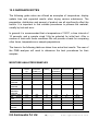
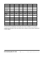
A typical test report will look as:
MOISTURE TEST
FILE NAME: RES00032
DATE:
13/12/2008
TIME:
09:38:07
SER NO:
AE12345678
Heading
File name used by analyzer to store result
From Analyzer
Serial number
TEST NO:
_ _ _ _ _ _ _ _ _
USER NO:
9876543210
Preset:
PST 05
Bread-4
A blank line for users to fill in a number if they wish.
User number
Preset method if used.
Result:
Heating:
Temp:
Rapid
Interval:
Stop:
Start:
INIT MASS:
% Moisture
Step
Step 1 120 C
Time 1 04:00
Step 2 110 C
Time 2 90:00
On
30 Sec
Time/Stable
60 Min
0.002 g
30 Sec
Manual
12.341 g
MODE TEMP
TIME
RESULT
Step0
65C
00:30
1.26
Step0
159C
01:00
2.11
Step0
157C
01:30
3.15
Step0
158C
02:00
3.79
Step0
156C
02:30
4.11
Step1
157C
03:00
4.19
Step1
149C
03:30
4.22
Step1
140C
04:00
4.24
Step2
131C
04:30
4.26
Step2
120C
05:00
4.27
Step2
111C
05:30
4.27
*********** AUTO STOP ***********
LAST TEMP:
TEST TIME:
FINAL MASS:
MASS LOSS:
RESULT:
Test settings
111C
05:30
11.820
0.521
4.27
Min
g
g
%M
%M
%M
%M
%M
%M
%M
%M
%M
%M
%M
%M
Measured initial mass.
Test Heading
Results printed once every 30 seconds as set by the
INCR time. Note temperature during first part of test is
120C X 130% as the Rapid function was enabled.
Step0 signifies the rapid function is active. After 3
minutes the Step1 value is the target.
TIME STOP if timed out or MAN STOP if user stopped
Summary of the test
English language version shown in the example.
E.G.Kantawalla Pvt Ltd
58 | P a g e
www.egkantawalla.com
After the test has finished the user can print either the complete test again or
only a summary by pressing the [Print/
] key before returning to normal
weighing.
The complete report is a copy of the data as shown above. If the summary
report is selected then the following is printed. Similar to the above except
without the interval readings.
MOISTURE TEST
FILE NAME: RES00032
DATE:
13/12/2008
TIME:
09:38:07
SER NO:
XXXXXXXXXXX
Heading
File name used by analyzer to store result
From Analyzer
Add serial number
USER NO:
XXXXXXXXXXX
TEST NO:
_ _ _ _ _ _ _ _ _
Preset:
Result:
Heating:
Temp:
Rapid
Interval:
Stop:
Start:
INIT MASS:
Add user number
PST 05
Bread-4
Leave a blank line for users to fill in a number if
they wish, not from Analyzer memory
Settings of the test conditions
% Moisture
Step
Step 1 120 C
Time 1 04:00
Step 2 110 C
Time 2 90:00
Manual
30 Sec
Time/Stable
60 Min
0.002 g
30 Sec
Manual
12.341 g
*********** AUTO STOP ***********
Measured initial mass.
LAST TEMP:
TEST TIME:
FINAL MASS:
MASS LOSS:
RESULT:
111C
05:30
11.820
0.521
4.27
Min
g
g
%M
TIME STOP if timed out or MAN STOP if user
stopped
Summary of results
Extra LF’s at end of the report
E.G.Kantawalla Pvt Ltd
59 | P a g e
www.egkantawalla.com
11.5 ANALYZER CONFIGURATION THROUGH THE SERIAL
INTERFACE
The analyzer can use the serial interface to set parameters for weighing test
and for analyzer configuration. The parameters are set by sending a line of
data that has the description and the setting desired.
It is possible to create a text file that contains all the data necessary to set he
test conditions for a particular test (or analyzer configuration) and send this
to the analyzer. The commands are not case sensitive, i.e. parity=0 and
PARITY=0 are both accepted.
11.5.1
TEST PARAMETERS
The parameters that control a test are listed below. To change a test
parameter it is necessary to send a command for the parameter to modify
along with the value to change.
For example to change the test parameters to use a single heat and set the
temperature to 115ºC send 2 commands.
Heat=0<cr><lf>
Single Temp=115<cr><lf>
All commands are in English regardless of the language selected for the
analyzer operation. The commands can be sent in both upper case letters
and lower case letter, i.e. “!KT” or “!kt” are both acceptable.
Moisture Result=1;
Heat=1;
Single Temp=100;
Step temp1=050;
Stem Time1=30:00;
Step temp2=080;
Stem Time2=30:00;
Step temp3=050;
Stem Time3=30:00;
Ramp Temp=100;
Ramp Time=30:00;
Rapid=0;
Interval Time=20;
Stop mode=0;
Stop time=10;
Stable Range=0.010;
Stable Time=10;
Start mode=0;
savepos=01;
E.G.Kantawalla Pvt Ltd
#0=%M, 1=%S, 2=%Atro_M, 3=%Atro_S
default=0;
#0=Single, 1=Ramp, 2=Step
default=0;
#050C to 160C,
default=100;
#050C to 160C,
default=100;
#Time 03:00 to 99:00
default=30:00;
#050C to 160C, 000C is off
default=100;
#Time 03:00 to 99:00
default=30:00;
#050C to 160C, 000C is off
default=100;
#Time 03:00 to 99:00
default=30:00;
#050C to 160C,
default=100;
#Time 03:00 to 99:00
default=30:00;
#Rapid heat 0=Off, 1=On, 2=Manual
default=0;
#05 sec to 99 sec
default=15;
#0=Time, 1=Stable, 2=Stab+Time
default=3;
#time = 03 to 99 min
default=20;
#grams default=0.010 for PMB 53, 0.10 for PMB 202;
#seconds, 01-99
default=02;
#0=Manual 1=Auto
default=0;
#memory location 01 to 49;
60 | P a g e
www.egkantawalla.com
Care must be used as some commands depend upon others to be effective,
For example sending a command for setting the heat to use a ramp but not
sending a temperature or time to use may cause incorrect operation if they
are not set to reasonable values.
The current settings can be printed or observed as described in sections
6.1.2 and 6.3.
11.5.2
PMB SETUP PARAMETERS
The parameters related to analyzer configuration are listed below. To
change a test parameter it is necessary to send a command for the
parameter to modify along with the value to change.
All commands are in English regardless of the language selected for the
analyzer operation. The commands can be sent in both upper case letters
and lower case letter, i.e. “PARITY=0” or “parity=0” are both acceptable.
Baud Rate=2;
Parity=0;
Print Test=1;
Output Format=0;
Continuous=1;
Interval=20;
Date Format=1;
User ID=1234567890;
Key Beeper=1;
Test Beeper=1;
Backlight=2;
Filter=1;
Stability=2;
Auto Zero=3;
Operator=000000;
Supervisor=000000;
Calibration Report=1;
Language=0;
#0=2400,1=4800,2=9600,3=19200,4=28400, default=1;
#0=none,1=Even,2=Odd ,default= 0;
#0=off,1=on, default=1;
#0=complete 1=summary ,default=0;
#0=off,1=on, default=0;
#00-99 ,default=1;
#0=Europe,1=USA,2=ASIA default=0;
#length=10 alpha-numeric characters;
#0=off;1=on default=1;
#0=off;1=on default=1;
#0=off,1=on,2=auto default=2;
#0=slow,1=normal,2=fast, default=1;
#0=1d,1=2d,2=5d,3=10d
default=2;
#0=off,1=1d,2=2d,3=5d
default=5;
#operator password
,must be 6 bytes;
#Supervisor password ,must be 6 bytes;
#0=off,1=on default=1;
#0=English, 1=German, 2=French, 3=Spanish
These commands are the same as will be set using the SETUP menu as
described in section 10. For example to change the beeper so it does not
sound at the end of a drying test, send the command
test Beeper=0<cr><lf>
E.G.Kantawalla Pvt Ltd
61 | P a g e
www.egkantawalla.com
When the analyzer receives a valid command, it will return the message E0.
But if an invalid input command is received, then the command is returned as
followsMessage returned
Remarks
11.5.3
E1
The analyzer can not recognise this command.
E2
String length is not right. i.e. key beeper=20<cr><if>
E3
String exceeds range. i.e. key beeper=2<cr><if>
E4
The string contains non-numeric character. i.e. key beeper=a
<cr><if>
E5
You do not have the authority to use this commands.
ANALYZER RECALL PARAMETERS
When parameters and results are saved in the memory. To recall all the
saved records, it is necessary to send a command as followsRecall result<cr><lf>
Recall config<cr><lf>
Recall preset<cr><lf>
Get all the test result
Get all the set up parameters
Get all the preset parameters
The PMB will return the list of parameters or data stored in the analyzer
menu.
The test results, test presets and analyzer configuration are all
stored separately.
To recall an individual parameter send the parameter name followed by a
question mark. For example sending heat=?<cr><lf> , the analyzer will send
back a message HEAT=1 for ramp heating applications.
11.5.4
REQUEST VALUES OF PARAMETERS
If the command for a parameter is sent with a “?” the PMB will send the value
currently stored in the analyzer. For example send:
Single temp=?<cr><lf> the PMB will send back
Single Temp=115<cr><lf>
E.G.Kantawalla Pvt Ltd
62 | P a g e
www.egkantawalla.com
11.6 CONTINUOUS OUTPUT
The PMB can use the interface to send the weight only to the output. This
setting is configured in the Serial Communications parameters, see section
10.1.1. When the output is set for Continuous the test reports are not
printed during a drying test and test results are not stored.
The weight will be printed using the time interval set with the Continuous
parameters, from 01 to 99 seconds.
The format is xxxxxxxxx<cr><lf> where the first 9 characters are the weight
with leading zeros replaced by spaces. First character is a “-“ for negative
weight.
The output will appear as:
_ _ _ 12.345
_ _ _ 12.345
etc.
E.G.Kantawalla Pvt Ltd
63 | P a g e
www.egkantawalla.com
12.0
SPECIFICATIONS & FEATURES
PMB 53
PMB 202
50g
200g
0.001g / 0.01%
0.01g / 0.05%
0.002g s.d.
0.02g s.d.
~3-4 sec.
~3-4 sec
2g
5g
Capacity
Readability
Repeatability
weighing
Stabilisation
Time
Weighing
Suggested
Minimum
Sample size
Repeatability
moisture
determination
(Sample is
sodium tartrate
dihydrate)
Pan size
Test method
End Criteria
3g sample 0.15%
10g sample 0.05%
3g sample
10g sample
0.4%
0.2%
90mm
%moisture
%solids
%moisture / dry weight
%solid / dry weight
Manual stop
Auto Stop with time
Auto stop change < set amount/time
Maximum test
time
99 minutes (1.5+ hours)
Heaters
Custom Halogen Lamp
400W
230VAC or 115VAC 50/60Hz.
E.G.Kantawalla Pvt Ltd
64 | P a g e
www.egkantawalla.com
Temperature
chamber
Temperature
profile
I/O
Stored Test
Setting
Stored Test
results
Data Output
Beeper
Language
RTC
Calibration
Power
Fuse
Environment
50 -160C
set in 1C steps
Standard (one step)
Step, up to 3 temperatures
Ramp, vs. time
Rapid option for Single and Step methods, 130% target for
3 minutes at start of test.
RS-232 Bi-directional Serial port
USB Serial Output
USB HUB Serial interface
1 Default setting, 49 User Settings
Stored by number and alpha/numeric name
Up to 99 test results stored by name
Ability to send data out via RS232 or USB Serial port.
Ability to store test results and test settings to USB
memory device using USB Host interface.
To sound when keys are pressed or to announce end of a
test, independently enable/disable
English, German, French or Spanish
Real Time Clock
Date formats, YMD, DMY, MDY
Time 24 hour clock
Manual calibration using external mass
20 or 50g
100 or 200g
Factory set, 115VAC or 230VAC, 50-60Hz., 400 watt.
5A, time lag, High Breaking capacity, 5 x20mm
0ºC to 40ºC, up to 90% RH. non-condensing
E.G.Kantawalla Pvt Ltd
65 | P a g e
www.egkantawalla.com
13.0 MENU STRUCTURE
WEIGHING
OPERATOR
[0/I] key
[
0/T
/ Esc]
[Print/
] key
[Start] key
[Dspl/
] key
[PST/
] key
PST XX
Standby/operate
Zero/Tare function
Print results
Begin drying a sample
Display alternate data on LCD
Store/Recall preset Test
PST Store
If PST XX is available then Store Current
test
If
PST
is
used
then
display
OVERWRITE?
{Setup/Enter} to Store current test
or ESC then return to weighing
PST Recal lPST XX Get stored data
Delete
PST XX
Delete PST number shown
E.G.Kantawalla Pvt Ltd
66 | P a g e
www.egkantawalla.com
[Test/
] key
Set Test Conditions
Result
% moisture
%
Solid
%
ATRO Moisture
%
ATRO Solid
Heat
Single
Set Temperature
Step
Set Temperature 1
Set Time 1
Set Temperature 2
Set Time 2
Set Temperature 3
Set Time 3
Ramp
Set Temperature
Set Time
Rapid heat On
Off
Manual Interval Set Interval time
Stop
Time
Stable
Set maximum time
Set Stable value
E.G.Kantawalla Pvt Ltd
67 | P a g e
www.egkantawalla.com
Set Stable Time
Time/Stable
Set maximum time
Set Stable value
Set Stable Time
E.G.Kantawalla Pvt Ltd
68 | P a g e
www.egkantawalla.com
Start
Manual
Auto
Print
Test
On
Off
Format
Comple
te
Summa
ry
No
[Setup/Enter] key
Display Supervisor menus
Sup.
Passcode
enabled?
Yes
Enter Supervisor Passcode
Display Supervisor menus
E.G.Kantawalla Pvt Ltd
69 | P a g e
www.egkantawalla.com
SUPERVISOR MENU
SERIAL Setup Interface Parameters Baud Rate
2400/4800/9600/19200/38400
Parity
Even/ Odd
Continuous
Interval
99 seconds
SETUP
Set 00 to 23
Setup analyzer parameters Time
Off
/
On/Off
01
to
Hour
Minute
Set 00 to 59
Second
set 00 to 59
Date Format
Europe
(dd/mm/yy)
USA
(mm/dd/yy)
ASIA
(yy/mm/dd)
Date
Year
Set 00 to 99
Month
set 00 to 12
Day
set date (00 to 31)
Weekday Set day of the week (Sun-Sat)
User ID
Set
Key Beeper
OFF
ID
number , 10 alpha-numeric characters
/
ON
E.G.Kantawalla Pvt Ltd
70 | P a g e
www.egkantawalla.com
Test Beeper
OFF
/
Backlight
OFF
/
Filter
Set
ON
ON / Auto
Filter slow, normal, fast
Language
Set to
English, German, French
or Spanish
Preview
Set On
or Off
CALIBRATION
CAL Mass
Start weight calibration
CAL Temp
Start Chamber Temperature Calibration
Calibration
Report
OFF / ON
PASSCODES
Set Passcodes
Operator
Enter old
Enter new
Supervisor
Enter old
Enter new
E.G.Kantawalla Pvt Ltd
71 | P a g e
www.egkantawalla.com
14.0 SAMPLE PREPARATION
Sample preparation is the single most important item for accurate results.
The sample must be prepared so the whole of the sample is heated uniformly
and the moisture is near the surface of the material.
For powders no further preparation is necessary. For most other materials
the sample should be ground, chopped, grated or otherwise made as fine as
possible. Liquids or paste may need to be spread onto glass fibre pads to
distribute them evenly and thinly. Some materials that may splatter as they
are heated (oils, butter) may need to be spread on the glass fibre pads or
mixed with dry sand.
Trial and error is often the only method to find the best method for the
material.
When the sample is placed on the weighing pan it should be spread as thin
and evenly as possible, do not compact the material. Ensure enough material
is used to assure good repeatability of the results. Typically samples of 3 to
8 grams are used.
Some materials will require special preparation. For example when testing
cheese, if the cheese is very soft it may be necessary to use dry sand as a
buffer material so it does not splatter or form a skin. To do this it would be
necessary to prepare the sand by drying it in an oven until you were certain
no moisture remains. Put the sand on the sample pan and tare the analyzer.
Mix the sand with the cheese so you have smooth mixture, spread this
mixture on the sample pan and then do the test.
An alternative to this preparation is to spread the cheese on dry spun glass
gauze to assist in spreading the heat and preventing splatter or skins
forming. Remember to tare the analyzer with the gauze in the weighing pan
for accurate results.
E.G.Kantawalla Pvt Ltd
72 | P a g e
www.egkantawalla.com
Other materials will hold water within them in a way that is not suitable for
this type of test. For example sugar will bind the water to the sugar
molecules so strongly that heat will not remove the water before the sugar is
burned.
Some plastics also are not suitable for this type of method due to the very
low percent moisture and the heat required to extract this moisture.
KNOW THE MATERIAL
In addition it is important to know enough about the materials so that you do
not endanger or inconvenience others. For example some solvents have
very low flash points that are not suitable for drying with heat sources that
can reach 100ºC. Other materials will cause odour or fumes that will be
dangerous or objectionable, consider drying fertilizer slurry without using a
vent to extract the odour.
E.G.Kantawalla Pvt Ltd
73 | P a g e
www.egkantawalla.com
15.0 GUIDANCE NOTES
The following guide notes are offered as examples of temperature, display
update time and expected results when drying various substances. The
preparation, distribution and amount of product can all significantly effect the
results. It is important to find suitable procedures to process the material,
usually by trial and error.
In general it is recommended that a temperature of 100ºC, a time interval of
10 seconds, and a sample sized 3-8g be selected for initial test. After a
number of tests with these conditions this will provide a basis for comparing
other times, temperatures or sample preparations.
The items in the following table are taken from actual test results. The user of
the PMB analyzer will need to determine the best procedures for their
samples.
MOISTURE ANALYZER EXAMPLES
MATERIAL
BUTTER
CEMENT
CHARCOAL
CHOCOLATE
POWDER
COCOA
POWDER
COFFEE
CREAMER
POWDER
CORNFLAKES
DRY
APPLE
PULP
DUST
FLOUR
GROUND
COFFEE
STANDARD
DEVIATION
DRYING
TIME(min)
15
15
10
5
AVERAGE
WATER
CONTENT
16.3
0.8
3.8
1.9
0.1
0.1
0.1
0.1
4.5
4-5
8-10
4
106
20
0.1
0.1
2
2-3
130
15
78.5
0.1
6-8
2-4
5-8
120
100
15
10
9.7
76.5
0
0.1
5-7
10-15
5-10
8-10
2-3
104
130
106
10
10
5
7.3
12.5
2.8
0.3
0.1
0.1
8-15
4-5
4
SAMPLE
MASS
(g)
2-5
8-12
8-10
2-4
DRYING
TEMPERATURE.(º C)
138
138
120
100
STROBE
TIME(s)
2-3
E.G.Kantawalla Pvt Ltd
74 | P a g e
www.egkantawalla.com
MARGARINE
MAYONNAISE
MILK
MILK
CHOCOLATE
MILK
POWDER
MUSTARD
PAPER
POLYAMIDE
POTATO
FLAKES
POWDERED
SOUP
RED WINE
SLIME
SUGAR
SUNFLOWER
OIL
WET APPLE
WHITE GLUE
YOGHURT
3-4
1-2
2-3
2-5
138
138
120
106
20
20
15
15
16
56.5
88
1.3
0.1
0.4
0.2
0.1
10
10
6-8
3.5
2-4
90
15
5
0.2
6
2-3
2-4
2-5
3-4
130
106
138
106
20
20
20
15
76.4
6.4
2
6.9
0.7
0.1
0.2
0.1
10
10
75
7.5
2-3
80
15
3
0.2
4.5-7
3-5
11-12
4-5
10-14
100
130
138
138
15
15
15
20
97.4
80
11.9
0.1
0.1
0.1
0
15-20
90
10
2
5-8
2-5
2-3
100
136
110
10
15
15
7.5
54.3
86.5
0
0.1
0
5-10
6-8
4.5-6.5
This list will be extended as information becomes available. If you wish to
supply any information that may help others, please contact Adam Equipment
or your dealer.
E.G.Kantawalla Pvt Ltd
75 | P a g e
www.egkantawalla.com
16.0
WARRANTY STATEMENT
Adam Equipment offers Limited Warranty (Parts and Labor) for the components failed due
to defects in materials or workmanship. Warranty starts from the date of delivery.
During the warranty period, should any repairs be necessary, the customer must inform
the supplier or Adam Equipment. The company or its authorised Technician reserves the
right to repair or replace any components at its own discretion. Any shipping costs
involved in sending the faulty units to a service centre is the customers responsibility.
The warranty will cease to operate if the equipment is not returned in the original
packaging and with correct documentation for a claim to be processed. All claims are at
the sole discretion of Adam Equipment.
This warranty does not cover equipment where defects or poor performance is due to
misuse, accidental damage, exposure to radioactive or corrosive materials, negligence,
faulty installation, unauthorised modifications or attempted repair or failure to observe the
requirements and recommendations as given in this User Manual.
Repairs carried out under the warranty does not extend the warranty period. Components
removed during the warranty repairs become the company property.
The statutory right of the purchaser is not affected by this warranty. The terms of this
warranty is governed by the UK law. For complete details on Warranty Information, see
the terms and conditions of sale available on our web-site
E.G.Kantawalla Pvt Ltd
76 | P a g e
www.egkantawalla.com
Manufacturer’s Declaration of Conformity
This product has been manufactured in accordance with the harmonised European
standards, following the provisions of the below stated directives:
Electro Magnetic Compatibility Directive 2004/108/EC
Low Voltage Directive 2006/95/EC
Adam Equipment Co. Ltd.
United Kingdom
FCC COMPLIANCE
This equipment has been tested and found to comply with the limits for a Class A digital device,
pursuant to Part 15 of the FCC Rules. These limits are designed to provide reasonable
protection against harmful interference when the equipment is operated in a commercial
environment. The equipment generates, uses, and can radiate radio frequency energy and, if
not installed and used in accordance with the instruction manual, may cause harmful
interference to radio communications. Operation of this equipment in a residential area is likely
to cause harmful interference in which case the user will be required to correct the interference
at his own expense.
Shielded interconnect cables must be employed with this equipment to insure compliance with
the pertinent RF emission limits governing this device.
Changes or modifications not expressly approved by Adam Equipment could void the user's
authority to operate the equipment.
W EEE COMPLIANCE
Any Electrical or Electronic Equipment (EEE) component or assembly of parts intended to be
incorporated into EEE devices as defined by European Directive 2002/95/EEC must be
recycled or disposed using techniques that do not introduce hazardous substances harmful to
our health or the environment as listed in Directive 2002/95/EC or amending legislation.
Battery disposal in Landfill Sites is more regulated since July 2002 by regulation 9 of the
Landfill (England and Wales) Regulations 2002 and Hazardous Waste Regulations 2005.
Battery recycling has become topical and the Waste Electrical and Electronic Equipment
(WEEE) Regulations are set to impose targets for recycling.
E.G.Kantawalla Pvt Ltd
77 | P a g e
www.egkantawalla.com
ADAM EQUIPMENT is an ISO 9001:2000 certified global company with more than
35 years experience in the production and sale of electronic weighing equipment.
Adam products are predominantly designed for the Laboratory, Educational, Medical,
retail and Industrial Segments. The product range can be described as follows:
-Analytical and Precision Balances
-Compact and Portable Balances
-High Capacity Balances
-Moisture analysers / balances
-Mechanical Scales
-Counting Scales
-Digital Weighing/Check-weighing Scales
-High performance Platform Scales
-Crane scales
-Medical Scales
-Retail Scales for Price computing
For a complete listing of all Adam products visit our website at
www.adamequipment.com
© Copyright by Adam Equipment Co. Ltd. All rights reserved. No part of this publication
may be reprinted or translated in any form or by any means without the prior permission of
Adam Equipment.
Adam Equipment reserves the right to make changes to the technology, features,
specifications and design of the equipment without notice.
All information contained within this publication is to the best of our knowledge timely,
complete and accurate when issued. However, we are not responsible for
misinterpretations which may result from the reading of this material.
The latest version of this publication can be found on our Website.
www.adamequipment.com
E.G.Kantawalla Pvt Ltd
78 | P a g e
www.egkantawalla.com