1
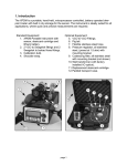
User manual Introduction ........................................................................................................ 5 Safety Information ....................................................................................... 6 Disclaimer .................................................................................................... 7 Intended Use ............................................................................................... 8 Battery Safety Precautions .......................................................................... 8 Identifying Parts of the Gateway ....................................................................... 9 Installation ........................................................................................................ 10 Activating the gateway: ............................................................................. 10 Installing MyVirtuoso Home App: ............................................................. 10 Connecting Mobile Device with Gateway: ................................................ 12 Connecting the Gateway to another router: ............................................. 13 Including (or Excluding) Devices ....................................................................... 14 Devices for Heating Control:...................................................................... 15 Thermostatic Radiator Heads ............................................................... 15 Comfort and Eco temperatures .................................................... 20 Manual mode................................................................................ 23 Valve temperature offset ............................................................. 25 Boiler Actuator ...................................................................................... 26 Temperature and Humidity Sensor ...................................................... 30 Devices for PV Monitoring & Control: ....................................................... 31 PV Balancer ........................................................................................... 31 Inductive Energy Meter ........................................................................ 32 Virtual Device ........................................................................................ 33 2 Other Automation & Control Functions: ................................................... 38 Device status ..................................................................................................... 38 Z-Wave network and general functionality ..................................................... 41 Routing table: ............................................................................................ 41 Update network topology: ........................................................................ 42 Mesh network:........................................................................................... 43 Widget configuration ........................................................................................ 44 Virtual device widget: ................................................................................ 46 Rules .................................................................................................................. 48 When Function ...................................................................................... 49 IF Function ............................................................................................. 49 Then Function ........................................................................................ 50 Rule Options .......................................................................................... 51 Heating Control using a Wireless Thermostat (including Boiler & Radiators): ................................................................................................. 54 Heating Control using Digital Thermostatic Heads (including Boiler Actuator):................................................................................................... 63 Rule 1 ..................................................................................................... 64 Rule 2 ..................................................................................................... 68 Rule 3 ..................................................................................................... 73 Lighting Control using a Light Sensor: ....................................................... 79 Edit, rename or delete the rule ................................................................. 88 Scenarios ........................................................................................................... 88 3 Lighting Control: ........................................................................................ 88 Edit, rename or delete the scenario .......................................................... 95 Notifications ...................................................................................................... 95 Battery level notification ........................................................................... 96 Battery level for notification.................................................................. 96 Battery notification repeat time ............................................................ 97 Notifications for device connection state ................................................. 97 Connectivity notification repeat time ................................................... 97 General notifications (alarms) ................................................................... 98 Notification using a motion sensor ....................................................... 98 Notification using a temperature sensor............................................. 104 General notification repeat time ......................................................... 112 Delete notifications automatically .......................................................... 113 Gateway management ................................................................................... 113 Edit, rename or delete a gateway ........................................................... 115 Activate login .................................................................................................. 115 Webcam configuration ................................................................................... 116 Webcam search: ...................................................................................... 116 Manual configuration: ............................................................................. 119 Webcam widget:...................................................................................... 121 Product Specifications .................................................................................... 124 4 Introduction MyVirtuoso Home is the complete home automation system for energy savings and remote control of your property, using a smartphone or tablet. It enables full control of devices using the same Z-Wave wireless protocol. Using MyVirtuoso Home, you can manage an integrated and comprehensive energy consumption. By implementing precise rules and using the various devices connected to the gateway, energy savings of up to 30% can be achieved. The user can enjoy improvements in comfort level, while at the same time, cost savings and environmental benefits can be achieved. One key advantage of the system is that the various mains powered wireless devices act as signal repeaters for the other devices in their range, so signals can bypass obstacles and the range is extended beyond the stated 30m (uninterrupted). Benefits include: Energy & cost savings through greater consumption control; Heating control for further cost savings & comfort; Automation of household devices & lighting; Security IP cameras; Wireless set-up - easy to install and retro-fit; Modular system – easy to expand over time; Remote access via smartphone or tablet; User friendly app. 5 Safety Information Before using this equipment, precautions need to be taken to reduce any fire risk or personal injury: 1. Read the instructions carefully and follow the precautions in this manual. All mains connections must be carried out by a trained and qualified person. 2. Pay particular attention to all potential hazards posed by devices marked (or indicated in the manual) with the symbol. 3. Disconnect any device from mains / mains chargers before cleaning. Clean devices with a damp cloth, do not use detergents. 4. Do not use devices in gas-filled environments. 5. Do not place the gateway near heat sources. 6. Only use original /SmartDHOME. 7. Do not place cables and/or power supplies under heavy objects. Also, avoid routes near sharp or abrasive objects and walkways. 8. Keep out of reach of children. 9. Do not carry out any maintenance on the device, instead contact your supplier. accessories provided by EcoDHOME 10. Contact your supplier if one or more of the following occurs to the gateway or an accessory (included or optional): a. If the product has come into contact with water or any other liquid. b. If the product has suffered obvious damage to the casing. c. If the product does not perform conforming to its stated characteristics. 6 d. If the product has undergone a noticeable degradation of performance. e. If the power cord has been damaged. Improper handling may damage the product and result in extra work to regain the desired operation, so avoid any repairs or adjustments not described in the manual. Electrical and Electronic Equipment waste (Applicable in the European Union and other European countries with separate collection systems). This symbol on the product or on its packaging indicates that this product shall not be treated as a common household waste. All products marked with this symbol must be disposed of through appropriate collection sites. Improper disposal may have negative consequences for the environment and for human health. The recycling of materials will help to conserve natural resources. For more information, please contact your local council, household waste disposal service or supplier. Disclaimer We cannot guarantee that the information concerning the technical characteristics or those contained in this document is correct. The product and its accessories described in this manual are subject to constant improvement and further development. For this reason, we reserve the right to modify components, accessories, technical specifications and related documentation of the product described in this document without notice. 7 Intended Use This device is designed for monitoring electricity consumption and control of devices connected to equipment installed in a workmanlike manner in residential, commercial or industrial buildings. Any other use is considered unintended use. Unauthorised modifications or reconstructions not described in this manual are not permitted. Battery Safety Precautions Do not burn, disassemble or puncture. Like other batteries of this type (paired devices), in case of tampering may discharge toxic materials which can cause injury. To reduce the risk of fire or personal injury, do not replace tablet batteries, contact an authorised service centre. Keep away from children. Remove batteries from unused devices where possible. 8 Identifying Parts of the Gateway Gateway MyVirtuoso Home Power Supply Status LED USB Ports Ethernet Port Gateway MyVirtuoso Home ES (Energy Saving) Power Supply Status LED HDMI port USB Ports Ethernet Port 9 Installation Activating the gateway: a. Connect the included power supply to the power inlet of the gateway and then to power outlet; the red LED remains solid. b. Connect one end of the network cable supplied to the Ethernet port of the gateway and the other to the LAN port of your router. The yellow LED light fixes, one green LED flashes and another green LED remains solid. NOTE: If the red LED remains solid, check the connection between the gateway and the router. c. The gateway will try to update if there are any updates available. We advise that you do not use the gateway for 60 minutes so that it can update without interruption. ATTENTION: Please do not unplug the power or network cables after the gateway has been connected for the first time. In order to update, the gateway requires connection to the internet. Installing MyVirtuoso Home App: ATTENTION: Please always update the app when a new version has been released to avoid system failures. a. Connect to the Wi-Fi signal of the router to which the gateway is connected. b. Access the App store for the mobile device you want to use. c. Search for “MyVirtuoso Home” and install it. 10 Fig.1 d. Now access the App and follow the Wizard for first connection and registration. ATTENTION: During the registration Wizard operation, gateway must have access to the internet. 11 Connecting Mobile Device with Gateway: Fig.2 ATTENTION: The first connection between your mobile device and the gateway must be performed under the same network. HOME mode – connection between the mobile device and the gateway in the same network. REMOTE mode – connection between the mobile device and the gateway under a different network or 3G network. NOTE: Remote connection to the gateway is only possible after the first connection – HOME mode required first time. NOTE: During the set-up make sure you select the correct time zone – both for gateway and smartphone. It is worth noting, that if you subsequently travel to a different time zone with your mobile device, and it automatically adjusts, the times for any pre-progammed actions appear to change, although times on the gateway remain as set. 12 OFFLINE – no connection between the mobile device and the gateway. In this case, check: a. The connection between the gateway and the router. b. If your mobile device is connected to the router, or if you have internet access. Connecting the Gateway to another router: If you have changed your home router, proceed as follows to restore the connection between the gateway and the MyVirtuoso Home App: a. Connect the gateway to the new router and connect your mobile device to its Wi-Fi network. b. Access the App. c. Go to ‘Settings’. d. Click on ‘Gateway Settings’. e. Scroll down, click on ‘Wi-Fi Network’ and update the Wi-Fi name. f. Once updated, the name should match the Wi-Fi of your new router. g. Finally, click on ‘Find Gateway. h. After a brief search, the connection should be ‘Mode: Home’: 13 Fig.3 Including (or Excluding) Devices Z-Wave is a wireless communication protocol designed for home automation, in particular for the control and supervision of remote applications in residential and light commercial property. Signals can be affected by metal in the signal pathway, eg RSJ’s or wiremesh security glass, and by the number and thickness of walls through which the Z-Waves travel. Consider using a smart socket or repeater in an intermediate location in order to extend the signals to more distant devices. Z-Wave technology provides a signal mesh capability so that signals are reached all over the property. To add or remove a device, you need to go through either the inclusion or exclusion procedures. For both procedures, the gateway routine is the same for all devices, the sequence of clicks may vary for individual devices – if in doubt consult the individual device instructions for these. Once included, the devices independently create a network of wireless connections. The mains powered devices also act as repeaters, transmitting the signal sent from nearby devices, strengthening the signal from devices furthest away from the gateway. 14 Battery powered devices are in sleep mode much of the time to conserve battery life. These devices do not act as repeaters. ATTENTION: Devices need to be within 1 meter of the gateway during the inclusion or exclusion procedure. ATTENTION: Please note that you can include up to 25 Z-Wave devices with a single MyVirtuoso Home gateway. NOTE: To exclude devices, follow the same procedure, simply select ‘Remove device’ from device settings menu, rather than ‘Add device’. Devices for Heating Control: Thermostatic Radiator Heads In this example, we will show how to include a thermostatic radiator head – see device specific instructions for full detail. NOTE: the default TTDZ head mode is ‘Auto’- this is correct for MyVirtuoso Home purposes. a. Select the main menu button to access ‘Device Settings’. 15 Fig.4 NOTE: the menu location may be different on some mobile devices. b. Select ‘Add Device’ from Device Settings menu: Fig.5 16 c. Carry out the inclusion procedure when the screen displays ‘Press the inclusion button of the device and wait....’: Fig.6 The TTDZ thermostatic heads can be included in one of two ways: 1. The device automatically pairs on insertion of the batteries. Insert one battery, when prompted with above message, add the second battery. When successfully included, the device appears on the app. 2. Insert the batteries, when prompted with above message, press the blue inclusion button by inserting the tool for 5 or more seconds. Press the button once quickly to perform the adapting procedure. 17 Refer to the TTDZ instruction manual for full inclusion / exclusion procedure. d. Once the device has been included in the system, its name, type and status will appear on the screen: Fig.7 NOTE: During the inclusion process specific information will be sent to the gateway, this usually takes a matter of minutes. If after inclusion, the device does not appear on the list, it means that device has not completed this communication. Wait for 30 seconds and then follow steps below: 18 Press the refresh button one or more times. Try to include. If the device does not appear, exclude it by following the instructions and try to include again. NOTE: If the device fails to include even after following all these steps, contact technical support. e. To change the name of the device, hold on its name and it opens a menu containing ‘Change description’. Select this and enter in an appropriate name: Fig.8 f. To change the set point of the thermostatic head manually press on the radio button: 19 g. Press and hold the slide button to set the temperature: h. Press again the radio button to save the set temperature: Comfort and Eco temperatures a. From the main screen, select main menu, then select ‘Device Settings’. b. Press and hold the name of the TTDZ digital head for a few moments: 20 Fig.9 c. Select ‘Set Eco/Comfort level’: Fig.10 d. Un-check ‘Use default’: 21 Fig.11 e. Set required temperature and confirm with ‘OK’: Fig.12 f. At this point, the temperatures you set will be used and applied by 22 the rules using these selected heads. NOTE: To set the Comfort and Eco temperature of all the heads simultaneously, select ‘Settings’ from the Homepage main menu, then select ‘Gateway Settings’ and scroll down to the ‘global’ temperature settings. Manual mode The manual mode allows the head to work with the On / Off commands. - the TTDZ is completely opened; - the TTDZ is completely closed; Follow this steps to put the TTDZ into the Manual mode: a. From the main screen, select main menu, then select ‘Device Settings’. b. Press and hold the name of the TTDZ digital head for a few moments and select ‘Edit Head Mode’: 23 Fig.13 c. Select “Manual mode” and confirm with “OK”: Fig.14 24 d. At this point, the TTDZ selected, will change the mode at the next wake-up time. Fig.15 Valve temperature offset Follow these steps to set the offset for the thermostatic heads included in your gateway: a. b. c. d. e. From the main page go to ‘Settings’. Select ‘Gateway Settings’. Scroll down to ‘Valve temperature offset’. Enter in the offset and confirm with ‘OK’. At this point the heads will follow the set-point temperature plus the temperature offset. For example, if you set the set-point of the head at 19°C and the offset to +1, the thermostatic head will adjust for 20°C. 25 Boiler Actuator Refer to manual for wiring diagram and inclusion/exclusi on operations See the wiring diagram in the actuator package. The actuator is wired to the mains supply to the boiler. Two other connectors are connected to the switch which is normally activated by a remote wall thermostat – when switch is closed, the boiler is actuated. There are two spare wires which should be blanked off. The remaining single wire is the aerial wire to pick up the Z-Wave signal. If the actuator is housed in the boiler unit, then arrange the aerial wire protruding outside of the metal casing of the boiler, to avoid the signal being blocked. If the boiler is not close to the gateway, then temporarily connect the power wires to a 13 amp plug in order to power up. For inclusion of this device do the following: a. Select the main menu button to access ‘Device Settings’: 26 Fig.16 b. Select ‘Add Device’ from Device Settings menu: Fig.17 c. When prompted by ‘Press the inclusion button of the device and 27 wait....’, press the button on the actuator three times rapidly to include the device: Fig.18 d. After some seconds the device should be included and displayed on the app: 28 Fig.19 e. To check full inclusion of the device, press the button on the actuator for 3 seconds, the light will flash once. You should be able to hear the actuator switching on / off if you press the actuator button on the app, which confirms it is functioning properly. - the actuator is ON; - the actuator is OFF; f. If pairing has not been successful then repeat inclusion process. g. Re-label device for easy identification – when in Device Settings, press on name, select ‘Change description’ and over-type with your chosen name, in this case ‘Boiler Actuator’: 29 Fig.20 Temperature and Humidity Sensor Refer to manual for inclusion/exclusi on operations The package leaflet gives instructions for pairing this device. Pair in close proximity to the gateway. 30 Follow the same procedure for adding devices, and when prompted by ‘Press the inclusion button of the device and wait....’, press the inclusion button three times in 1.5 seconds. After some seconds the device should appear on the app: Fig.21 The sensor should then be placed on the wall in a suitable place, avoiding direct sunlight and close proximity to radiators. Re-label the device for easy identification. NOTE: the sensor is not a thermostat – it relays temperature and humidity data to the gateway. Devices for PV Monitoring & Control: PV Balancer 31 The PV Balancer manual gives complete instructions for pairing this device (and the rule set-up procedure). In brief: Pair in close proximity to the gateway. Follow the same procedure for adding devices, and when prompted by ‘Press the inclusion button of the device and wait....’, press the inclusion button on the actuator three times rapidly to include. After the message disappears, press the refresh button on the app. The app will then display the actuator (balancer) on the Homepage. If pairing has not been successful, then repeat inclusion process. Re-label device for easy identification – when in Device Settings, press on name, select ‘Change description’ and over-type with your chosen name, in this case ‘PV Balancer’. For full instructions see PV Balancer manual. Inductive Energy Meter To create the balance for PV Balancer, 2 single-phase inductive meters need to be included in the system: to measure the PV production; to measure household consumption. 32 NOTE: These devices can be used with all gateways to simply measure energy consumed / produced. Pair in close proximity to the gateway. Follow the same procedure for adding devices, and when prompted by ‘Press the inclusion button of the device and wait....’, press the inclusion button on the meter three times rapidly to include. After the message disappears, press the refresh button on the app. The app will then display the meter on the Homepage. If pairing has not been successful, then repeat inclusion process. Re-label device for easy identification – when in Device Settings, press on name, select ‘Change description’ and over-type with your chosen name, in this case either ‘PV Production’ or ‘Household Consumption’. For full instructions see Inductive Energy Meter Manual Virtual Device ATTENTION: Please note that this function is only available with the MyVirtuoso Home ES. With this version of the gateway, you can check real-time production from a photovoltaic system, the overall household consumption and use any available balance to power specific devices. 33 a. Select Device Settings from main menu. b. Select ‘Add Virtual Device’ from the device settings menu: Fig.22 c. Name the virtual device, in this case ‘Balance’: 34 Fig.23 d. Select ‘PV Production’: Fig.24 e. After selecting the production meter, press the minus sign ‘ ’: 35 Fig.25 f. Select the ‘Household Consumption’: Fig.26 g. Press ‘Done’ to save the virtual device: 36 Fig.27 h. To check it has been created and saved, scroll down the Devices list to find the virtual device ‘Balance’: Fig.28 37 NOTE: If the virtual device does not appear, press device list. to refresh the Other Automation & Control Functions: These devices include: Signal repeaters, Smart sockets, Motion sensors, Door-window sensors, Lux sensors. For all of the above devices, follow the same inclusion / exclusion procedure, and see device instructions for specific device sequence. Device status a. Battery powered devices. NOTE: Press the icon to get the device battery status. Battery powered devices are in sleep mode most of the time to conserve battery life. Once included, they communicate with the gateway every 15 minutes. b. Connection status of devices. To see if a device is in communication with the gateway, select Device Settings from the main menu and then scroll down the device list to find the device in question. Next to the device, you will see ‘Last Device Contact’, this will tell you when it last communicated – remember, some devices communicate every 15 minutes. Any time will be based on the time programmed into your smartphone or 38 tablet i.e. time local to you, not necessarily the gateway. Fig.29 You can also see another indication of the connection status: Device is reachable by gateway; Device is not accessible; NOTE: If the device icon is crossed check to see if device is powered or is too far away from the gateway. Once powered or brought within range (possibly with repeater), press the icon to restore connectivity. Within a few minutes, the ‘X’ symbol should disappear from the icon showing connectivity has been restored. c. Charts and historical data . On the Homepage of the application press the devices historical data. icon to access the For example, the temperature and humidity sensor data can be seen below: 39 Fig.30 NOTE: Other time periods can selected – see figure. Fig.31 40 Z-Wave network and general functionality Routing table: This indicates the strength of communication between the Z-Wave devices paired with the gateway. If the 2 devices are communicating directly with each other, this is shown as dark green in the table. Light green indicates that 2 devices (nodes) are not communicating directly, but through more than one path. This is still considered to be a stable connection. A yellow block is considered to be an unstable connection. A red block does not indicate no connection at all, but the connection is so poor that communication between the 2 devices is likely to fail. Grey blocks are where same device appears on both axes. Access the routing table as follows: a. From the Homepage select main menu, then select Settings. b. Select Gateway Settings from the list. c. Scroll down to ‘Routing Table’ and select: 41 Fig.32 Update network topology: After including all required devices, we recommend that you update the network topology of the system. This operation will automatically update the routing table as devices choose other / better ways to communicate with the gateway. Update the network topology as follows: a. From the Homepage main menu select ‘Settings’. b. Select ‘Gateway Settings’ from the list. c. Scroll down to ‘Routing Table’ and select it. d. From the menu within routing table section, select ‘Update Network’: 42 Fig.33 To make sure the system has updated the topology properly, it is worth doing this 3-4 times. NOTE: The system requires a minimum of 15 minutes to fully update the network topology. This option is also available within ‘Device Settings’. Mesh network: One of the advantages of the Z-Wave system is the ‘mesh network’ the devices create. Once included, the devices independently create a network of wireless connections. The mains powered devices (nodes) act as repeaters, transmitting the signal sent from devices too far from the gateway to secure a reliable communication. The diagram below shows this type of mesh in operation: 43 Fig.34 Mesh networks are extremely reliable, as each device is connected to many other devices. If a node fails in the network, for whatever reason, the neighboring nodes simply seek other paths for transmitting the signal. The capacity of the network thus increases as devices are added and the mesh strengthens. Widget configuration On the main screen of the application the default set-up includes: all classes of device; weather and clock widgets. To temporarily view one class of device only, press on found on top left of screen, or swipe screen from left to right; this shows the device categories, then select one of them. Or, for a more permanent selection, proceed as follows: a. From main menu select ‘Widget Configuration’: 44 Fig.35 b. Press on and then select the desired category of devices: Fig.36 45 c. Finally, go back to the main screen to see the layout chosen: Fig.37 Virtual device widget: ATTENTION: The virtual device and associated functions are available with MyVirtuoso Home ES version only. The Virtual Device Widget has the ability to store data on the consumption of the property (Orange), the photovoltaic production (Green) and the balance (blue if positive). By pressing the icon you can see the historical consumption and production data / kWh): 46 Fig.38 Fig.39 NOTE: When the consumption in the home is greater than the 47 photovoltaic production, the balance color changes to dark blue: Fig.40 Rules The MyVirtuoso Home Rules allow you to totally automate your system. You can define one or more conditions which if met, will trigger an automatic event. For example, you can turn on the heating system when the temperature in the home drops below a set threshold, or adjust lighting when LUX levels drop below a set level. Furthermore, with pre-set conditions, you can configure ‘Push’ notifications on your mobile device. 48 Fig.41 When Function When is the period of activation for the rule. If you do not select a period the Rule will be active 24/7. Below shows that the Rule will be active from Monday to Friday from 06:00 to 13:00: Fig.42 IF Function 49 IF states that if one or more conditions is met, one or more commands in Then section will be activated. Below shows a device (door sensor) in IF. The condition set suggests that if the sensor detects door opening then the rule will trigger an event: Fig.43 Then Function Then contains actions that are performed if the conditions in IF are satisfied. For example, screenshot below shows that if the sensor detects door opened actuator: , the Then part of the rule will switch on the selected Fig.44 50 Rule Options Fig.45 a. ‘Activate opposite condition’: Activating this option generates the contrary rule to the one you are creating. For example, screenshot below shows that if the sensor detects door – window sensor is open , then the rule will turn the selected actuator on : Fig.46 51 With the opposite condition activated window is shut , if the sensor detects the door – , Then actuator selected will turn off . NOTE: This option is enabled by default. To turn it off, press the illuminated button. b. ‘AND Condition for IF Devices’: This option only required when IF section contains multiple devices and you want both set conditions to be satisfied. Screenshot below shows two devices and two conditions in the IF section. Checking ‘AND Condition for IF Devices’ means both conditions need to be satisfied to trigger an event. In this case, the door sensor needs to detect that the door is opened and the temperature needs to be less than 20°C to trigger the Then event, in this example switching on the actuator: Fig.47 In this case, ‘AND Condition for IF Devices’ is not active , and therefore it is sufficient for either of the two conditions to be satisfied for the switch 52 to be activated. So if the sensor detects that the door-window is open, or that the temperature has dropped below 20°C, then the actuator will be switched on. NOTE: The ‘AND Condition for IF Devices’ is disabled by default. c. ‘Put THEN Devices into opposite state at schedule end’: This option refers to When and triggers the opposite state for devices after schedule ends. For example: Screenshot below shows that the Rule will be active Monday to Friday from 06:00 to 13:00, if the sensor detects the door is opened , Then switch is turned on : Fig.48 Checking the ‘Put THEN Devices into opposite state at schedule end’ switches off the actuator at 13:00 without considering IF conditions. 53 NOTE: The ‘Put THEN Devices into opposite state at schedule end’ is on by default. d. ‘Then’ activation delay: This option allows you to trigger the Then event, in this case turn on the actuator, after a set time. For example, if the time set in this option is 10 minutes, this means that 10 minutes after the If condition is satisfied, the Then event will take place. e. Opposite condition activation delay: This option allows you to reverse the Then event for the opposite condition, in this case turn off the actuator, after a set time. For example, if the time set is 10 minutes, this means that 10 minutes after the door is shut (opposite to If condition), the actuator will switch off (opposite to Then condition). Heating Control using a Wireless Thermostat (including Boiler & Radiators): In addition to using the manual controls found on the Homepage of the App, it is possible to fully control your heating system using our sophisticated Rules capability. This enables the system to control individual radiators and the boiler according to user requirements. NOTE: This example uses a temperature sensor to control the system. Before setting-up any Rules, go to the Settings section to select the correct time-zone (UTC 00:00) and the Comfort / Eco temperatures you require. a. Select ‘Rule settings’ from the main Settings Menu: 54 Fig.49 b. Select the symbol to start a new rule. c. Type the name of your new rule and select ‘OK’: Fig.50 55 d. Press on and select ‘When’ from the rule drop-down menu: Fig.51 e. Check the required days of the week and type in (or move dial) the start and finish times for each time slot: 56 Fig.52 NOTE: Multiple time slots allowed for each day. NOTE: If the “Program definition” window doesn't appear, press and hold on the empty calendar. f. Then press ‘OK’ to display settings on calendar. NOTE: Time periods chosen will be saved when the rule itself is saved. g. Press on select ‘If’ from the rule drop-down menu: Fig.53 h. Check the box for temperature sensor you want to use and ‘OK’ to save: 57 Fig.54 i. Select the temperature option and enter the temperature below which you want the heating to switch on, then ‘OK’: Fig.55 58 Fig.56 j. Select and ‘Then’ from the rule drop-down menu: Fig.57 59 k. Check the radiator valves and boiler actuator you want to control, then ‘OK’: Fig.58 l. Select Comfort mode for heads and put the boiler button into the state: 60 Fig.59 m. Select and then Rule Options from the rule drop-down menu. n. 1st and 3rd buttons should already be checked – these switch off the boiler/put heads into Eco when desired temperature is reached (Opposite rule) and after a heating period finishes (Put ‘Then’ devices into opposite state at schedule end): 61 Fig.60 o. Return to rule screen , then press on to save. ATTENTION: The heating system is now ready to operate according to your time schedules and temperature settings. NOTE: To edit the time schedules, open up the rule and press the calendar section. Either, add a new time slot in the way you entered up the original schedules, or check the relevant box and select delete icon . This can be repeated for any day, simply select the required day and the saved time slots appear – delete as required, then add new schedules as before. 62 Fig.61 To edit the rule name, do the following: a. Press and hold on the rule name. b. Press on to change the rule name and confirm with ‘OK’. To delete the rule: a. Press on to delete. NOTE: If you want to disable the rule, use the On/Off button in the rule list. Heating Control using Digital Thermostatic Heads (including Boiler Actuator): This is a 3-Rule system, using the Comfort and Eco settings on the digital thermostatic radiator heads to control the heating system. 63 a. Once they are set up, the user only needs to update the time schedules in Rule 1. b. Before setting-up any Rules, go to the Settings section to select the correct time-zone (UTC 00:00) and the Comfort / Eco temperatures you require (different temperatures can be set for each head). c. Select Rule Settings from the main Settings menu: Fig.62 d. Select the symbol to start a new rule. Rule 1 Sets times when heating is required. a. Label rule – in this case ‘Heating Times’, then ‘OK’: 64 Fig.63 b. Select and then ‘When’ from rule drop-down menu: Fig.64 65 c. Check the required days of the week and type in (or move dial) the start and finish times for each time slot and then press “OK”: Fig.65 NOTE: If the “Program definition” window doesn't appear, press and hold on the empty calendar. NOTE: Multiple time slots allowed for each day. d. Select and ‘Then’ from the drop-down: 66 Fig.66 e. Check the digital heads, then ‘OK’: Fig.67 67 f. The blue area indicates that the digital thermostatic heads will be in the Comfort mode (temperature), the grey area is Eco mode (temperature): Fig.68 g. Press on to save the rule. Rule 2 Sets heating to come on whenever one head is open. a. Select Rule Settings from the main Settings menu. b. Select the symbol to start a new rule. c. Label the new rule – in this case ‘Heating ON’: 68 Fig.69 d. Select and then ‘If’ from rule drop-down menu: Fig.70 69 e. Check radiator valves, then ‘OK’: Fig.71 f. Select Head state and status for each thermostatic head: 70 Fig.72 g. Select and ‘Then’ from rule drop-down menu: Fig.73 71 h. Check ‘Heating’ (Boiler Actuator), then ‘OK’: Fig.74 i. Put Heating button into on position : 72 Fig.75 j. Select and “Rule options” from the rule drop-down menu. k. Put all the buttons in the off position : Fig.76 l. Return to rule screen and then on to save. Rule 3 Sets heating to switch off when all heads are in closed position. a. Select Rule Settings from the main Settings menu. b. Select the symbol to start a new rule. c. Label the new rule – in this case ‘Heating OFF’: 73 Fig.77 d. Select and then ‘If’ from rule drop-down menu: Fig.78 e. Check thermostatic heads, then ‘OK’: 74 Fig.79 f. Select Head state and status for each head: Fig.80 75 g. Select and ‘Then’ from rule drop-down menu: Fig.81 h. Check the Boiler actuator, then ‘OK’: 76 Fig.82 i. Select status for Heating: Fig.83 j. Select and then ‘Rules option’ from rule drop-down menu. k. Check ‘And condition for IF devices’ : 77 Fig.84 NOTE: Above setting means boiler remains on until all heads are closed. l. Return to rule screen and then on to save. 78 Fig.85 ATTENTION: The heating system is now ready to operate according to your time schedules and settings. NOTE: Once all 3 rules have been set up, all you have to do is alter time schedules in Rule 1 (and Comfort / Eco temperatures as required). To edit the time schedules, open up the rule and press the calendar section. Either, add a new time slot in the way you entered up the original schedules, or check the relevant box and select delete icon . This can be repeated for any day, simply select the required day and the saved time slots appear – delete as required, then add new schedules as before. NOTE: If you want to disable the rule, use the On/Off button in the rule list. Lighting Control using a Light Sensor: All devices paired to the MyVirtuoso Home gateway can be controlled using Rule programming. The following example uses a rule to control 79 lighting according to saved time slots and light sensor lux measurements (Motion sensor (PIR) and door-window sensor activation can also be used). NOTE: In addition to lights, any switch / actuator or smart socket chosen from the device list can be controlled in a similar fashion. To control lighting (or other devices) according to saved times alone, see Scenarios / Lighting Control section. Follow rule procedure outlined below: a. Select Rule Settings from the main settings menu: Fig.86 b. Select the symbol to start a new rule. c. Label the new rule – in this case “Lighting”: 80 Fig.87 d. Select and then ‘When’ from rule drop-down menu: Fig.88 81 e. Check the required days of the week and type in (or move dial) the start and finish times for each time slot: Fig.89 NOTE: If the “Program definition” window doesn't appear, press and hold on the empty calendar. NOTE: Multiple time slots allowed for each day f. Select and then ‘If’ from rule drop-down menu: 82 Fig.90 g. Check boxes for device used to control lighting – in this case the Light Sensor, then ‘OK’ (could also use other sensors, such as the motion or door-window): Fig.91 83 h. Press on the Light sensor name: Fig.92 i. Type in the Lux level below which you want the lights to switch on, then ‘OK’: 84 Fig.93 j. Select and ‘Then’ from rule drop-down menu: Fig.94 85 k. Select devices you want to activate, then ‘OK’: Fig.95 l. Put button into the state: Fig.96 86 m. Select and then “Rule options” from the rule drop-down menu. n. 1st and 3rd buttons should already be checked – these switch off the lights when the desired lux level is reached (Opposite rule) and after a lighting period finishes (Put ‘Then’ devices into opposite state at schedule end): Fig.97 o. Return to rule screen and then on to save: ATTENTION: The lighting system is now ready to operate according to your time schedules and settings. NOTE: To edit the time schedules, open up the rule and press the calendar section. Either, add a new time slot in the way you entered up the original schedules, or check the relevant box and select delete icon . This can be repeated for any day, simply select the required day and the saved time slots appear – delete as required, then add new schedules as before. 87 NOTE: If you want to disable the rule, use the On/Off button in the rule list. Edit, rename or delete the rule To edit the rule name, do the following: a. Press and hold on the rule name. b. Press on to change the rule name and confirm with ‘OK’ To delete the rule, do the following: a. Press and hold on the rule name. b. Press on to delete. To edit the rule: a. Press on the rule name to access to it. NOTE: If you want to disable the rule, use the On/Off button in the rule list Scenarios The difference between a rule and a scenario is that a scenario does not require the ‘If’ (one or more conditions) to trigger an event, as it is based on time schedules alone. All devices paired to the gateway can be controlled using scenario programming. Lighting Control: The following example uses a scenario to control lighting according to saved time slots. 88 To control lighting according to saved time slots and light levels (PIR or door-window sensor activation), see Rules / Lighting Control using a Light Sensor. Follow scenario procedure outlined below: a. Select Scenario Settings from the main menu: Fig.98 b. Select the symbol to start a new rule. c. Type in the name of your new scenario, then ‘OK’: 89 Fig.99 d. Select and then ‘When’ from rule drop-down menu: Fig.100 90 NOTE: The menu location may be different on some mobile devices. e. Check the required days of the week and type in (or move dial) the start and finish times for each time slot: Fig.101 NOTE: If the “Program definition” window doesn't appear, press and hold on the empty calendar. NOTE: Multiple time slots allowed for each day. f. Then press on and select ‘Add devices’ from scenario drop-down: 91 Fig.102 g. Check boxes for device(s) to activate – in this case the hall light, then ‘OK’: Fig.103 92 h. Put buttons into state: Fig.104 i. Press on and select “Scenario options” from the scenario dropdown menu. j. Make sure the button is checked : 93 Fig.105 NOTE: The ‘Put ‘Then’ devices into opposite state at end of schedule’ is on by default. ATTENTION: If you have already set up a rule where times and devices conflict with scenario, select Disable rules from the same menu, then check rule in question – selected rules will temporarily disable when scenario operates. k. Return to scenario screen and press on to save. The lighting system is now ready to operate according to your schedules. NOTE: To edit the time schedules, open up the scenario and press the calender section. Either, add a new time slot in the way you entered up the original schedules, or check the relevant box and select delete icon . This can be repeated for any day, simply select the required day and the saved time slots appear – delete as required, then add new schedules as before. 94 NOTE: If you want to disable the scenario, use the On/Off button in the scenario list. Edit, rename or delete the scenario To edit the scenario name, do the following: a. Press and hold on the scenario name. b. Press on to change the scenario name and confirm with ‘OK’ To delete the scenario, do the following: a. Press and hold on the scenario name. b. Press on to delete. To edit the scenario: a. Press on the scenario name to access it. NOTE: If you want to disable the scenario, use the On/Off button in the rule list. Notifications MyVirtuoso Home is able to send different notifications. For example, the gateway is able to send a notification at the time when a sensor detects an opening door, a motion sensor detects movement or a smoke detector the presence of smoke. In addition, the gateway will send a notification when the batteries in one of the included devices drops below a set level, or when one of the devices is no longer accessible. 95 NOTE: To view the notifications go to the main screen and press the message section: Fig.106 Battery level notification Notifications about the status of the batteries are always active. The gateway will automatically send a notification when the battery level of one of the included devices drops below the pre-set level. Battery level for notification Change the battery level for notification as follows: a. From the main menu go to ‘Settings’. b. Select ‘Gateway Settings’. c. Select ‘Battery Level Warning’. 96 d. Enter in desired percentage and confirm with ‘OK’. e. At this point you will be notified when the battery level of one of your paired devices drops below the set level. Battery notification repeat time To change the repeat time for this type of notification: a. b. c. d. From the main menu go to ‘Settings’. Select ‘Gateway Settings’. Select ‘Battery notification repeat time’. Enter in the desired time and confirm ‘OK’. NOTE: We recommend that you set a time interval that does not result in too many messages. e. At this point the gateway will send battery level notification messages as often as the time interval you have set, regardless of battery charge status. Notifications for device connection state Notifications for the status of device accessability are always active. The gateway will automatically send a notification when one of the paired devices can no longer be accessed by the gateway. Connectivity notification repeat time Change the repeat time for this type of notification as follows: a. From the main menu go to ‘Settings’. 97 b. Select ‘Gateway Settings’. c. Select ‘Connectivity notification repeat time’. d. Enter in the desired time and confirm with ‘OK’. NOTE: We recommend that you set a time interval that does not result in too many messages. At this point the gateway will send device connection state notification messages as often as the time interval you have set. General notifications (alarms) MyVirtuoso Home is able to send push notifications to the user using Rule settings. MyVirtuoso Home will notify you when one or more conditions contained in a rule are satisfied. Notification using a motion sensor This example shows how to set up a Notification using a motion sensor. The notification is sent when the sensor detects movement. NOTE: In order to create this type of notification you must first pair a motion sensor with your gateway. a. From the main menu go to ‘Rule Settings’. b. Press the symbol and name your new rule – in this case ‘Motion alarm’: 98 Fig.107 c. Press and select ‘When’: Fig.108 99 d. Set the required time. e. Press and select ‘IF’: Fig.109 f. Select the sensor and confirm with ‘OK’: 100 Fig.110 g. Set the status of the motion sensor: Fig.111 101 - Motion detected - No motion detected h. Press and select ‘Then’. i. Select ‘Notify’ and confirm with ‘OK’: Fig.112 j. Check ‘Send Push Notification’ and ‘Priority’ if you want a notification highlit on the bulletin board: 102 Fig.113 k. Press and select ‘Rule Options’. l. Uncheck ‘Activate opposite condition’: 103 Fig.114 - Opposite condition activated - Opposite condition de-activated NOTE: If the ‘Activate opposite condition’ is checked, the gateway will notify when there is no movement detected. m. Go back a screen and press to save the notification. Notification using a temperature sensor In the next example we will show you how to set up a notification with a temperature and humidity sensor. The notification will be sent at the time the sensor detects the temperature passes the set temperature (whichever way it is set). 104 NOTE: In order to create this type of notification you must first pair a temperature sensor with your gateway. a. From the main menu go to ‘Rule Settings’. b. Press symbol and name your new rule – in this case ‘Low temperature alarm’: Fig.115 c. Press and select ‘When’: 105 Fig.116 d. Set the required time. e. Press and select ‘IF’: 106 Fig.117 f. Select the sensor and confirm with ‘OK’: Fig.118 107 g. Press on temperature: Fig.119 h. Set the desired temperature and confirm with ‘OK’: 108 Fig.120 i. Press and select ‘Then’. j. Select ‘Notify’ and confirm with ‘OK’: 109 Fig.121 k. Check ‘Send Push Notification’ and ‘Priority’ if you want a notification highlit on the bulletin board: 110 Fig.122 l. Press and select ‘Rule Options’. m. Uncheck ‘Activate opposite condition’: 111 Fig.123 - Opposite condition activated - Opposite condition de-activated NOTE: If the ‘Activate opposite condition’ is checked, the gateway will notify when the temperature is above 15°C. n. Go back a screen and press to save the notification. General notification repeat time To change the repeat time for this type of notification: a. From the main menu go to ‘Settings’. b. Select ‘Gateway Settings’. c. Select ‘Notification repeat time’. 112 d. Enter in the desired time and confirm ‘OK’. NOTE: We recommend that you set a time interval that does not result in too many messages. e. At this point the gateway will send the notification messages as often as the time interval you have set, about the condition of the device which was set as a trigger. Delete notifications automatically You can configure gateway to delete notifications automatically. To set the automatic delete time do the following: a. From the main screen go to ‘Settings’. b. Select ‘Gateway Settings’. c. Select ‘Time of day messages delete’ and set the time. NOTE: ‘Time of day messages delete’ sets the actual time of day you want messages deleted. d. Then select ‘No. of days messages display’ and enter in the number of days required before automatic deleting. Gateway management With MyVirtuoso Home you can manage multiple gateways with the same mobile device. Proceed as follows if you would like to add another gateway: 113 a. Connect the gateway to your Wi-Fi router. b. Access the MyVirtuoso Home App. c. From the Homepage, access the main menu and select ‘Gateway Management’. NOTE: the menu location may be different on some mobile devices. d. Press on . e. Type in and enter the Serial Number. f. Type in and enter the Security Key. NOTE: The activation keys mentioned above are shown on a card contained in the MyVirtuoso Home box. g. Confirm with ‘OK’. h. Once you add the gateway you can select it. i. After selecting gateway the application will try to connect to it.. j. After a short search, the ‘Gateway Information’ window will appear, indicating status, connection type and mode. Fig.124 k. Press ‘OK’. 114 Edit, rename or delete a gateway To edit the gateway, do the following: a. Press and hold on the gateway name. b. Press on to change the gateway name and confirm with ‘OK’ To delete the gateway from the list, do the following: a. Press and hold on the gateway name. b. Press on to delete. Activate login You can enable a login facility to the application on your mobile device. Follow these steps to create a login: a. From the main screen, select ‘Settings’ from the main menu. b. Select ‘Login’. c. Select ‘Enable Login’. NOTE: E-mail address entered during registration will automatically become user name. d. Enter password. e. Close the application and re-enter using your user name and password: 115 Fig.125 Webcam configuration ATTENTION: The maximum number of webcams you can configure with your MyVirtuoso Home gateway depends on the maximum number of users that can be connected to your router. Webcams are not Z-Wave devices, so the number you can set up with system, are in addition to 25 device limit already mentioned. Webcam search: This procedure allows the gateway to automatically search for webcams within the same network. Proceed as follows to search for connected webcams: 116 a. From the main screen, select main menu, then select ‘Webcam Settings’. b. Select ‘Search for Webcams’ from webcam menu: Fig.126 c. After a brief search, webcams found by the gateway will appear on the screen: 117 Fig.127 d. Press and hold on the webcam name and then select ‘Change Parameters’: Fig.128 e. Enter the webcam details and then ‘OK’. 118 f. To return to the main screen press . g. Select ‘Security’ from the left hand menu, then press the icon below to view the webcam streaming image: Fig.129 Manual configuration: If the automatic search did not detect any webcam, you can configure your webcam using the manual mode. To configure a webcam manually with MyVirtuoso Home, proceed as follows: a. Select ‘Webcam Settings’ from the main menu on Homepage. b. Select ‘Add Webcam’ from webcam menu. c. Enter webcam details, confirming with ‘OK’: 119 Fig.130 d. Press to return to the main screen. e. Select ‘Security’ from the left hand menu, then press the icon below to view the webcam streaming image: 120 Fig.131 Webcam widget: After configuring your webcam with MyVirtuoso Home, you can add the widget to the main screen of the application. To add a webcam widget, proceed as follows: a. Select Widget Configuration from the main menu. b. Press on symbol. c. Select ‘Webcam’ from the list and confirm with ‘OK’: 121 Fig.132 d. Return to the main screen. e. After a brief loading period, the Webcam Widget will appear on the main screen: 122 Fig.133 f. Press on to display another webcam: Fig.134 123 Product Specifications MyVirtuoso Home ES (Energy Saving) Protocol used by Sensors & Actuators Z-Wave Maximum number of Sensors & Actuators 25 Transmission Frequency 868.42 MHz Connectivity Ethernet / Wi-Fi Power Supply Mains / batteries (some paired devices) Gateway Dimensions 160(W) x 120(D) x 40(H) Gateway Weight 334g Operating Temperature 0 – 40°C Fig.137 MyVirtuoso Home Protocol used by Sensors & Actuators Z-Wave Maximum number of Sensors & Actuators 25 Transmission Frequency 868.42 MHz Connectivity Ethernet / Wi-Fi Power Supply Mains / batteries (some paired devices) Gateway Dimensions 160(W) x 120(D) x 37(H) Gateway Weight 360g Operating Temperature 0 – 40°C Fig.138 124 www.ecodhome.co.uk [email protected] Re Rev. 08/2015 P/P/N 01335-0351-00 125