1
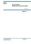
User’s Manual Model HH350G Suspension Type Holder IM 19H1B1-01E R IM 19H1B1-01E 4th Edition i <INTRODUCTION> INTRODUCTION The HH350G suspension type holder is used to hold the SS300G MLSS sensor, PH8EFP KCl filling type pH sensor, PH8ERP KCl refillable type pH sensor, OR8EFG KCl filling type ORP sensor, OR8ER KCl refillable type ORP sensor, and D030G dissolved oxygen sensor. This holder allows the sensor to be held at any depth for continuous measurement even though when the solution to be measured is flowing past. When a suspension type holder with jet washing system is used, a water jet automatically cleans the sensor tip at the desired interval with the sensor installed. To fully exploit the capabilities of this product, thoroughly read through the User’s Manual before use. Throughout this User’s manual, important items with respect to handling are indicated by a Warning or Caution designation, depending upon the relative degree of importance. For safety reasons and to prevent the possibility of damaging the product, user should strictly observe these items. 1. Specification check The length of the guide pipe and whether or not a cleaner is to be added can be specified for the HH350G suspension type holder. Upon taking receipt of the product, unpack carefully, checking that no damage has occurred during transport. Check to ensure that the received product is exactly what was ordered and that no parts are missing. 2. Contents This manual covers all of the information for handling the HH350G suspension type holder, including installation, inspection and maintenance, For details related products, refer to the relevant User’s Manual shown below. Model DO402G Title Dissolved oxygen converter IM No. IM 12J05D02-01E DO30G Dissolved oxygen sensor IM 12J5B3-01E SS400G MLSS converter IM 12E6B1-02E SS300G MLSS sensor IM 12E6C1-01E SS350G Wiper-Washing controller IM 12E6E1-01E PH8ERP KCl Refillable type pH sensor IM 12B7K1-02E PH8EFP KCl Filling type pH sensor IM 12B7J1-01E FLXA202,FLXA21 2-Wire Liquid Analyzer IM 12A01A02-01E PH201G*B Distributor IM 19B1E4-02E PH450G pH/ORP Converter IM 12B07C05-01E OR8EFG KCl Filling type OPR Sensor IM 12C07J01-01E OR8ERG KCl Refillable type OPR Sensor IM 12C04K01-01E Media No. IM 19H1B1-01E 4th Edition : Oct. 2015 (YK) All Rights Reserved Copyright © 1998, Yokogawa Electric Corporation IM 19H1B1-01E ii <INTRODUCTION> For the safe use of this equipment n Safety, Protection, and Modification of the Product • In order to protect the system controlled by the product and the product itself and ensure safe operation, observe the safety precautions described in this user’s manual. We assume no liability for safety if users fail to observe these instructions when operating the product. • If this instrument is used in a manner not specified in this user’s manual, the protection provided by this instrument may be impaired. • Be sure to use the spare parts approved by Yokogawa Electric Corporation (hereafter simply referred to as YOKOGAWA) when replacing parts or consumables. • Modification of the product is strictly prohibited. • The following symbols are used in the product and user’s manual to indicate that there are precautions for safety: n Notes on Handling User’s Manuals • Please hand over the user’s manuals to your end users so that they can keep the user’s manuals on hand for convenient reference. • Please read the information thoroughly before using the product. • The purpose of these user’s manuals is not to warrant that the product is well suited to any particular purpose but rather to describe the functional details of the product. • No part of the user’s manuals may be transferred or reproduced without prior written consent from YOKOGAWA. • YOKOGAWA reserves the right to make improvements in the user’s manuals and product at any time, without notice or obligation. • If you have any questions, or you find mistakes or omissions in the user’s manuals, please contact our sales representative or your local distributor. n Warning and Disclaimer The product is provided on an “as is” basis. YOKOGAWA shall have neither liability nor responsibility to any person or entity with respect to any direct or indirect loss or damage arising from using the product or any defect of the product that YOKOGAWA can not predict in advance. IM 19H1B1-01E iii <INTRODUCTION> n Symbol Marks Throughout this user’s manual, you will find several different types of symbols are used to identify different sections of text. This section describes these icons. WARNING Indicates a potentially hazardous situation which, if not avoided, could result in death or serious injury. CAUTION Indicates a potentially hazardous situation which, if not avoided, may result in minor or moderate injury. It may also be used to alert against unsafe practices. IMPORTANT Indicates that operating the hardware or software in this manner may damage it or lead to system failure. NOTE Draws attention to information essential for understanding the operation and features. Tip This symbol gives information that complements the current topic. SEE ALSO This symbol identifies a source to be referred to. IM 19H1B1-01E iv <INTRODUCTION> After-sales Warranty n Do not modify the product. n During the warranty period, for repair under warranty consult the local sales representative or service office. Yokogawa will replace or repair any damaged parts. Before consulting for repair under warranty, provide us with the model name and serial number and a description of the problem. Any diagrams or data explaining the problem would also be appreciated. l If we replace the product with a new one, we won’t provide you with a repair report. l Yokogawa warrants the product for the period stated in the pre-purchase quotation Yokogawa shall conduct defined warranty service based on its standard. When the customer site is located outside of the service area, a fee for dispatching the maintenance engineer will be charged to the customer. n In the following cases, customer will be charged repair fee regardless of war- ranty period. • Failure of components which are out of scope of warranty stated in instruction manual. • Failure caused by usage of software, hardware or auxiliary equipment, which Yokogawa Electric did not supply. • Failure due to improper or insufficient maintenance by user. • Failure due to modification, misuse or outside-of-specifications operation which Yokogawa does not authorize. • Failure due to power supply (voltage, frequency) being outside specifications or abnormal. • Failure caused by any usage out of scope of recommended usage. • Any damage from fire, earthquake, storms and floods, lightning, disturbances, riots, warfare, radiation and other natural changes. n Yokogawa does not warrant conformance with the specific application at the user site. Yokogawa will not bear direct/indirect responsibility for damage due to a specific application. n Yokogawa Electric will not bear responsibility when the user configures the product into systems or resells the product. n Maintenance service and supplying repair parts will be covered for five years after the production ends. For repair for this product, please contact the nearest sales office described in this instruction manual. IM 19H1B1-01E v <CONTENTS> Model HH350G Suspension Type Holder IM 19H1B1-01E 4th Edition CONTENTS INTRODUCTION....................................................................................................i For the safe use of this equipment....................................................................ii After-sales Warranty...........................................................................................iv 1. Overview..................................................................................................... 1-1 1.1 Features of HH350G Suspension Type Holder............................................... 1-1 1.2 Specifications..................................................................................................... 1-2 1.2.1 Standard Specifications...................................................................... 1-2 1.2.2 Model and Suffix codes...................................................................... 1-3 1.2.3 External Dimensions........................................................................... 1-3 2. Names and Functions............................................................................... 2-1 3. Installation, Piping and Wiring................................................................. 3-1 3.1 3.2 3.3 4. Preparations for lnstallation............................................................................. 3-1 3.1.1 Inserting the Sensor............................................................................ 3-1 3.1.2 Incorporating the Guide Pipe to the Sensor Mounting Section.......... 3-3 Installation.......................................................................................................... 3-4 3.2.1 Selecting Measurement Point............................................................. 3-4 3.2.2 Selecting a Place of Installation for the HH350G Suspension Type Holder 3-4 3.2.3 Securing the HH350G Suspension Type Holder................................ 3-4 3.2.4 Installing the HH350G Suspension Type Holder................................ 3-4 Piping and Wiring (for Washing)...................................................................... 3-6 3.3.1 Items to Note with Regard to Piping Work.......................................... 3-6 3.3.2 Piping Examples................................................................................. 3-7 3.3.3 Wiring.................................................................................................. 3-8 Maintenance............................................................................................... 4-1 4.1 Inspecting Sensor Retaining O-ring................................................................ 4-1 4.2 Inspecting the Cleaning Device........................................................................ 4-2 4.2.1 Inspecting Jet Washing Device........................................................... 4-2 4.2.2 Inspecting Solenoid Valve................................................................... 4-2 Customer Maintenance Parts List.......................................CMPL 19H01B01-01E Revision Information................................................................................................i IM 19H1B1-01E Blank Page 1. Overview 1.1 Features of HH350G Suspension Type Holder ● ● ● ● 1-1 < 1. Overview > This holder is not affected by the properties of the solution to be measured and reliably holds the sensor in the correct position. Because the sensor support section does not rotate around the guide pipe due to the flow of the solution to be measured, the sensor can be firmly held at the measurement point. The sensor is held at an angle of 30°, thus stable measurement is ensured. Since bubbles do not easily stick on the sensor tip (detection section), noise-free measurement can be conducted in a wide range of processes. The sensor measuring position can be set at any location. The sensor mounting section is hung from a stainless chain along the guide pipe. Therefore, the sensor position can be adjusted to any level. Sensor maintenance is easy. Because the sensor mounting section can be pulled up along the guide pipe to hold it at any position, maintenance can be performed by simply detaching the sensor. Staining by algae, etc. Lift the sensor mounting position Algae, etc. can be removed from the lifted area Figure 1.1 Measuring Position (with washing device) ● Automatic cleaning on the sensor tip can be performed at designated intervals with the sensor installed If the jet cleaner (option) is used, the tip of the sensor can be cleaned periodically, thus stable measurement is possible. IM 19H1B1-01E 1-2 < 1. Overview > Mounting bracket Guide pipe Mounting bracket Arm Chain mounting section Chain Stanchion (2-inch pipe for fixing) Sensor mounting section Sensor Sensor Figure 1.2 1.2 Jet cleaner (Option) Holding Sensor by HH350G Suspension Type Holder (with jet cleaner) Specifications 1.2.1 Standard Specifications Applicable sensor: General pH Sensor PH8ERP, PH8EFP, General ORP Sensor OR8ERG, OR8EFG, Dissolved Oxygen Sensor DO30G, MLSS Sensor SS300G Note1: When using a KCl filling type sensor, a stanchion or mounting bracket for the KCl tank is required separately. Note2: Not applicable for special pH/ORP sensor or PH4/OR4 sensor. Mounting: 2-inch pipe mounting vertical. Note: Make sure the mounting pipe firmly installed. Cleaning method:Water or air jet cleaning Material: Holder; Polypropylene and stainless steel (equivalent to SUS304) Guide-pipe; Stainless steel (equivalent to SUS304) Mounting bracket;Stainless steel (equivalent to SUS304) Cleaning unit; Weight: 6.4 to 13.8 kg Stainless steel (equivalent to SUS304),PVC, and polypropylene Temperature range: 0 to 80°C Note: The temperature may be limited by the specifications of the sensor. Flow rate: 1 m/s or less Note: The flow speed may be limited by the specifications of the sensor. Utility required for cleaning device: Utility Pressure Flow rate Water jet 100 to 200 kPa 5 to 20 l/min Air jet 100 to 200 kPa 10 to 20 Nl/min Note 1: Pressure and flow rate must be simultaneously satisfied at the holder inlet port. Note 2: A large braid-reinforced tube of ø22 x ø15 is recommended for supply due to the flow rate.• Guide to guide pipe submersion depth (1) When the water level continuously fluctuates at a rate of 25 cm/sec. or more: Do not submerge the guide pipe more than 2 m deep. (2) When the water level continuously fluctuates at a rate of 20 cm/sec. or more and less than 25 cm/sec: Do not submerge the guide pipe more than 2.5 m deep. IM 19H1B1-01E 1-3 < 1. Overview > 1.2.2 Model and Suffix codes Model Suffix Code ........................................ HH350G — -NN Guide-Pipe Length -00 -10 -20 -30 -40 Cleaning System -NN -JT Connection for Cleaning -NN -JP -NP Description ................ Suspension holder ................ Always -NN ................ No guide-pipe ................ 1m ................ 2m ................ 3m ................ 4m ................ None ................ Jet cleaning (The solenoid valve must be specified separately.) ................... None ................ Rc 1/2 ................ 1/2 NPT female thread Option Code 1.2.3 External Dimensions Unit: mm (1000) 100 Approx. 265 190 46 Min. 200 to Max. 800 (Pitch 50) 150 130 140 140 L (Standard Pipe Length) Approx. 60 Sensor 96 Weight Specification of Holder (Model and Code) Figure 1.3 Nominal Holder Length (L) 1000mm [Code : -10] 2000mm [Code : -20] 3000mm [Code : -30] 4000mm [Code : -40] Without Cleaner HH350G-NN-□□-NN-NN 6.4 kg 8.7 kg 11 kg 13.3 kg With Jet Cleaner HH350G-NN-□□-JT-□P 6.9 kg 9.2 kg 11.5 kg 13.8 kg External Dimensions with jet cleaning IM 19H1B1-01E 1-4 < 1. Overview > Guide pipe (SUS304) 50 x 50 x (Pipe length + 150 mm) (1000) 100 Arm pipe (SUS304) 50 x 50 x 1 m Min. 200 to Max. 800 (Pitch 50) Approx. 215 Unit: mm 190 46 150 130 140 140 L Stanchion 2-inch pipe (Standard Pipe Length) 161 Approx. 60 Sensor 96 Approx. 453 Note: When using holder with wiper cleaning, select option code /WP (with wiper cleaning) of SS300G. Figure 1.4 IM 19H1B1-01E External Dimensions with wiper washing for reference only 2. 2-1 < 2. Names and Functions > Names and Functions Stanchion (2-inch) Cleaning utility tube Mounting bracket Guide pipe *1 Arm pipe assembly Chain holding section *2 Sensor cable Sensor securing socket Sensor mounting section *3 Sensor Jet Cleaner *4 *1:Based on the specifications of the sensor mounting section, lower the sensor to a depth that prevents the sensor mounting section from being rotated due to water flow. *2:This section holds the chain that is used to suspend the sensor mounting section. During measurement, it secures the sensor mounting section in the desired position and during maintenance it is used to lift the mounting section to a position that permits easy access to the equipment. *3:Because the sensor is held at an angle of 30°, bubbles do not stagnate at the sensor tip. *4:The jet cleaner ejects air or water to clean the sensor tip. Figure 2.1 Names and Functions IM 19H1B1-01E Blank Page 3. 3-1 < 3. Installation, Piping and Wiring > Installation, Piping and Wiring As an option, a jet cleaner can be attached to the suspension type holder. When a suspension type holder with cleaner is used, a utility (air or water) pipe is installed. In addition, if cleaning is to be performed automatically at designated intervals, wiring for a solenoid valve for the utility piping system. 3.1 Preparations for lnstallation 3.1.1 Inserting the Sensor When installing the suspension type holder, incorporate the sensor beforehand. 1. Incorporating the SS300G (MLSS sensor) Insert the sensor according to the following instructions. SEE ALSO With respect to the SS300G MLSS sensor, there are a number of items to be aware of. Refer to the separate User’s Manual (IM 12E6C1-01E). NOTE Use care not to damage the tip of the MLSS glass prism. (1) Pass the SS300G cable through the socket of the sensor mounting section and securing O-ring. First, remove the socket screwed in the sensor mounting section. Pass the sensor cable through the O-ring and incorporate the O-ring in the sensor main unit part, then pass the sensor cable through the socket of the holder mounting section. Socket O-ring Figure 3.1 Incorporating the MLSS sensor (2) Insert the sensor into the sensor mounting section from the top and screw in the socket through which the sensor cable is passed to secure the sensor. (3) When the wiper-washing device is specified as an option for the MLSS sensor, attach the wiperwashing device to the MLSS sensor. For details, refer to the separate User’s Manual IM 12E6C1-01E. IM 19H1B1-01E 3-2 < 3. Installation, Piping and Wiring > 2. Incorporating DO30G (dissolved oxygen sensor) Use the following procedure for incorporation. SEE ALSO For details of how to assemble the dissolved oxygen sensor (DO30G), refer to the concerned User’s Manual (IM 12J5B3-01E). NOTE Use care not to damage the tip of the dissolved oxygen sensor. (1) Pass the cable of DO30G through the socket and securing O-ring of the sensor mounting section. Incorporate the O-ring in the sensor main unit after passing through the sensor cable, then pass the sensor cable through the socket of the holder mounting section. Socket O-ring Figure 3.2 Incorporating the dissolved oxygen sensor (2) Insert the sensor into the sensor mounting section from the tip and screw in the socket through which the sensor cable was passed to secure the sensor. 3. Incorporating PH8EFP and PH8ERP Use the following procedure for incorporation. SEE ALSO For details of how to assemble the PH8EFP KCl filling type pH sensor or PH8ERP KCl refillable type pH sensor, refer to the appropriate User’s Manuals (IM 12B7J1-01E and IM 12B7K1-01E, respectively). NOTE Use care not to damage the junction and glass electrode on the tip of the pH sensor. IM 19H1B1-01E < 3. Installation, Piping and Wiring > 3-3 (1) Pass the cable of PH8EFP (or PH8ERP) through the socket and securing O-ring of the sensor mounting section. Incorporate the O-ring in the sensor main unit after passing through the sensor cable, then pass the sensor cable through the socket of the holder mounting section. Socket O-ring Figure 3.3 Incorporating the pH sensor (2) Insert the sensor into the sensor mounting section from the tip and screw in the socket through which the sensor cable was passed to secure the sensor. 4. Incorporating OR8EFG and OR8ERG Use the following procedure for incorporation. SEE ALSO For details of how to assemble the OR8EFG KCl filling type ORP sensor and OR8ERG KCl refillable type ORP sensor, refer to the appropriate User’s Manual (IM 12C07J01-01E and IM 12C04K01-01E, respectively). NOTE Use care not to damage the junction and indicator electrode on the tip of the ORP sensor. (1) Pass the cable of OR8EFG (or OR8ERG) through the socket and securing O-ring of the sensor mounting section. Incorporate the O-ring in the sensor main unit after passing through the sensor cable, then pass the sensor cable through the socket of the holder mounting section. (see Figure 3.3.) (2) Insert the sensor into the sensor mounting section from the tip and screw in the socket through which the sensor cable was passed to secure the sensor. 3.1.2 Incorporating the Guide Pipe to the Sensor Mounting Section The guide pipe of the suspension type holder is used by attaching it with the SUS mounting bracket and arm pipe that are accessories to the pipe of nominal diameter of 2-inch. The suspension type holder is used by attaching the sensor mounting section to the SUS304 angled pipe of 50 mm x 50 mm x pipe length x 1.5 mm plate thickness. IM 19H1B1-01E 3-4 < 3. Installation, Piping and Wiring > 3.2 Installation 3.2.1 Selecting Measurement Point With the HH350G suspension type holder, install the attachable sensors in the measurement position. Under normal conditions, select a measuring position that satisfies the following requirements. • Install the sensor at an appropriate location where the typical measured value of the measurement subject can be obtained. Avoid locations where the solution to be measured is unevenly distributed since it will lead to hunting for a measured value. Also avoid locations where air bubbles are generated. • The position at which the temperature or flow speed of the measured solution matches the usage conditions of the sensor and holder. A fast flowing solution that contains sand may damage the sensor. 3.2.2 Selecting a Place of Installation for the HH350G Suspension Type Holder Sensors must be calibrated and maintained regularly. Thus the HH350G suspension type holder should be installed in a location that satisfies the following conditions. • Space enough to allow calibration and maintenance near the measurement point • A location where washing utility requirements are met. (In case a washing device is used). 3.2.3 Securing the HH350G Suspension Type Holder The HH350G suspension type holder is secured using a bracket mounted to a 2-inch pipe. The securing pipe, which has enough strength to attach the HH350G, is provided vertically. 3.2.4 Installing the HH350G Suspension Type Holder (1) Attach the mounting bracket to the stanchion (securing pipe). (2) Attach the mounting bracket to the arm pipe and then secure with the mounting bracket attached to the stanchion. (3) Attach the bolt to the guide pipe to prevent the sensor mounting section from coming off. Use the parts (bolt, nut, washer, spring washer, chain holding plate) included in the arm pipe mounting bracket to attach the guide pipe. (4) Put the end of the chain of the sensor mounting section in the groove of the chain holding section attached to the guide pipe. Hook the chain to the three claws of the chain holding section. Engage the sensor mounting section on the guide pipe and use the securing screw to secure the sensor mounting section. (5) Gently drop the sensor mounting section with incorporated sensor until it is in the measurement position. Dropping it rapidly may damage the sensor tip. (6) When the sensor reaches the desired measurement position, hook the chain to the three claws of the main holding section at the appropriate length. IM 19H1B1-01E 3-5 < 3. Installation, Piping and Wiring > l Pull up the sensor mounting section of the suspension type holder when performing calibration or maintenance (1) To perform maintenance, pull up the sensor mounting section until the socket that secures the sensor can be reached by hand and hook the chain to the chain holding section to hold the sensor mounting section in place. (2) Loosen and take off the socket that secures the sensor and pull up the sensor from the screw section. (3) Make sure that there is no cracks or permanent distortion on the O-ring attached to the sensor when performing calibration or maintenance. Socket Sensor mounting section Screw section Figure 3.4 Detaching the Sensor For MLSS sensor equipped with a wiper washing device, perform maintenance by detaching the sensor mounting section from the guide pipe with the MLSS sensor secured in place. Detach the sensor mounting position from the guide pipe by opening it left and right after removing the securing screw and nut. (see Figure 3.4.) For details of how to attach or remove the wiper washing device, refer to the MLSS Sensor User’s Manual. NOTE Use care not to stain or wet the sensor cable terminal processing section while performing the work. Check the following after installation of the suspension type holder. • The tip of the sensor is located at a position that is not influenced by bubbles. • Even though the liquid surface fluctuates, the sensor tip must always be completely submerged in the solution to be measured. IM 19H1B1-01E 3-6 < 3. Installation, Piping and Wiring > 3.3 Piping and Wiring (for Washing) This description is for a suspension type holder with jet washing device. SEE ALSO For details related to handling of optional wiper washing devices for the MLSS sensor, refer to the SS350G Wiper Washing Controller User’s Manual. 3.3.1 Items to Note with Regard to Piping Work Piping is provided to the suspension type holder with jet washing device to supply the air or water used for washing. Use care with regard to the following items when installing the piping. • Maintenance of the washing device should be easy to carry out. For the piping for the section adjacent to the suspension type holder, use a soft hose (netimpregnated soft polyvinyl chloride resin tube). There must be some leeway in the length. • In winter, provide heat insulation if there is a possibility that washing water will freeze. Washing is performed at designated intervals (any time cycle can be set to the converter). • Use a pipe diameter sufficient to ensure that the necessary washing pressure and flow volume is satisfied. For air pipes, select about JIS 15A nominal diameter size. The solenoid valve incorporated in the washing pipe line should be JIS 15A aperture (pipe joint port) that operates normal close (“close” when energized). Yokogawa provides solenoid valves with the following specifications. [Model PH8MV Solenoid Valve] Pilot kick operated, 2-port valve. Open when energized. Fluid: Normal tap water, industrial water, or air Operating pressure: 0 to 1 MPa Forward (reverse) pressure resistance: 2 MPa Fluid temperature: Water; 5 to 60°C Air; -10 to 60°C Cv: 4.5 Process connection: Rc 1/2 Power supply: 100/110/200/220 V AC, 50/60 Hz Power consumption: 10 W Construction: IP53 Material: Body; Bronze Sealing; Nitrile rubber Ambient temperature: Maximum 50°C Cable inlet connection: G 1/2 Weight: IM 19H1B1-01E Approx. 0.9 kg 3-7 < 3. Installation, Piping and Wiring > 3.3.2 Piping Examples (1) Air Jet Cleaning Contact signal (from converter) Driving power supply Pressure reducing valve From air supply (pressure: 2 MPa or less) Solenoid valve JIS 15A hard pipe Figure 3.5 Example Showing Air Jet Cleaning (2) Water (industrial water) Jet Washing Contact signal (from converter) Driving power supply Solenoid valve Industrial water (pressure: 100 to 200 kPa) Ball valve JIS 15A hard pipe Figure 3.6 Example Showing Water (industrial water) Jet Washing (3) Water (tap water) Jet Washing Contact signal (from converter) Driving power supply Tap water (pressure: 100 to 200 kPa) Float valve Tank Stop valve Pump Figure 3.7 Example Showing Water (tap water) Jet Washing IM 19H1B1-01E 3-8 < 3. Installation, Piping and Wiring > 3.3.3 Wiring Normally, washing is executed when a "cleaning" contact signal is received from the converter. SEE ALSO The contact output must be set to "cleaning" function. For details, refer to the user’s manual supplied with each converter. When SS350G Wiper-Washing Controller is used, refer to User’s manual IM 12E6E1-01E for the wiring Install wiring so that when the contact signal is output drive power is supplied to the solenoid valve (or pump), and utility (air or water flows into the washing device). The cleaning contact of the converter has the following specifications. Cleaning contact specifications Contact type: Relay contact (dry contact) Contact capacity: Refer to user’s manual supplied with the converter. Converter Solenoid valve Cleaning contact output terminal Solenoid valve driving power supply Figure 3.8 Solenoid Driving Circuit Wiring Output timing of "cleaning" contact signal • The converter is first turned on, then cleaning is executed after the preset cleaning interval elapses. If the automatic cleaning function is set to "stop", when "execute" is set cleaning is executed after the cleaning interval lapses. Execution of manual cleaning and "automatic cleaning start" command • The converter can be manually operated any time through key operation. • The automatic cleaning start command can be sent any time by inputting the contact signal to the converter. IM 19H1B1-01E 4. 4-1 < 4. Maintenance > Maintenance When measuring operation is performed correctly, it is not necessary to do inspection and maintenance of the HH350G suspension type holder. Perform inspection and maintenance described in this chapter when performing calibration or sensor maintenance. 4.1 Inspecting Sensor Retaining O-ring Periodically inspect the O-ring of the sensor holding section for deterioration such as permanent distortion or cracks. When the O-ring is found to have deteriorated, replace it with the new one. As a rule, remove the sensor cable connection to replace the O-ring. Use care not to wet or stain the cable terminal processing section. To replace the O-ring while the sensor cable is still connected, the O-ring is incorporated along the circumferential side of the sensor body. Remove stains on the sensor; use care not to damage the Oring in the process (see Figure 4.1). Socket O-ring Figure 4.1 Replacing the O-ring at the sensor holding section (in case the O-ring is incorporated from the sensor tip) IM 19H1B1-01E 4-2 < 4. Maintenance > 4.2 Inspecting the Cleaning Device This chapter only applies to suspension type holders with jet cleaning device. SEE ALSO For maintenance of the MLSS sensor with wiper washing, refer to the MLSS sensor's mamual. Inspect the device for the following two items. 1. Check for clogging of the nozzle hole of the jet washing device. 2. With the solenoid valve closed, check whether or not the washing utility is discharged. If the existence of any error is not found in the installed state, inspect again by detaching the suspension type holder. To perform maintenance on the wiper washing device while it is attached to the MLSS sensor, perform maintenance by removing the device from the guide pipe while the sensor mounting section is still secured to the MLSS sensor. For details of how to attach and remove the wiper washing device, refer to the MLSS Sensor User’s Manual. 4.2.1 Inspecting Jet Washing Device When the nozzle is clogged, the cleaning effect of the jet washing device will decrease. Use a 0.8 mm thick metal needle or the like to unclog the nozzle. Remove the jet washing device from the holder to inspect the interior of the washing device. If excessively dirty with slurry or algae, clean thoroughly. F0402.ai Figure 4.2 Unclogging the Nozzle 4.2.2 Inspecting Solenoid Valve Check that the cleaning utility is not discharged from the jet washing device while the solenoid valve is closed. Replace the solenoid valve if the leak is more than a small amount that does not affect measurement. IM 19H1B1-01E Customer Maitenance Parts List HH350G Suspension Type Holder 5 7 6 11 8 9 4 10 3 2 13 14(internal) 1 12 Item 1 2 3 4 5 6 1 1 1 1 2 1 Description Holder Assembly Socket Bracket Pipe For guide-pipe : 1 m For guide-pipe : 2 m For guide-pipe : 3 m For guide-pipe : 4 m Bracket Pipe 7 8 9 10 11 7 13 7 7 2 Hexagon Bolt Washer Plain Washer Spring Nut Hexagon U-Bolt Assembly 1 1 1 Jet Nozzle Assembly Screw O-ring 12 13 14 Parts No. K9171NX Qty 1 1 1 Below Y9100SU Y9406LU K9433NX All Rights Reserved, Copyright © 1997, Yokogawa Electric Corporation. Subject to change without notice. CMPL 19H01B01-01E 1st Edition : Dec.1997 (YK) 3rd Edition : Nov. 2011 (YK) i Revision Information : Model HH350G Suspension Type Holder Title Manual No. : IM 19H1B1-01E Nov. 2015/4th Editionn Review with the GS version UP; page-i ♦ INTRODUCTION “2. Contents“ add FLXA202 and delete PH400G, PH202G, PH202S,PH100, PH8PU1. Nov. 2011/3rd Edition Page layout changed by InDesign P1-3 FU20 pH/ORP sensor was deleted; P1-4 some error correction of Figure1.3, Figure1.4 added; CMPL 19H01B01-01E revised to 3rd edition (P/N addition for O-ring). Oct. 2007/2nd Edition Revised and corrected all over and IM style & format renewed. Dec. 1998/1st Edition Newly published. IM 19H1B1-01E Blank Page