1
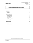
Metasys Network Technical Manual 636
Function Modules Section
Technical Bulletin
Issue Date 0194
Input Analog Function Module-101
Introduction
Page
3
•
Product Overview
3
•
Theory of Operation
3
•
Design Considerations
•
Application Wiring Diagrams
5
— Voltage and Current
5
— 2-Wire RTD
6
*4
Commissioning Procedures
7
•
Overview
7
•
Assumptions
7
•
Procedure
7
•
Line Compensation (RTD Only)
8
•
Device Verification
8
Troubleshooting Procedures
9
•
Testing for an Open Line
9
•
Ordering Information
11
* Indicates a change since the last printing.
©
1994 Johnson Controls, Inc.
Order No. 636-030
1
2 Function Modules—Input Analog Function Module-101
Introduction
Product Overview
The Input Analog Function Module (FM-IAN101-0) connects two
independent analog inputs through a single FM slot to a Digital Control
Module 140.
Theory of
Operation
The control process is as follows (step numbers correspond to numbers in
Figure 1):
1. Analog input signals (either 0 to 10 VDC or 1K RTD) from up to two
field devices arrive via the terminal blocks to the IAN. (0 to 20 mA
DC signals can be converted to voltage and read by use of an external
resistor.)
2. The IAN conditions the signals and protects the base frame with
current limiting devices.
3. A switch on the IAN front panel selects the input type (both channels
must be of the same type, either both voltage or both RTD).
4. The IAN routes each input analog signal to the DCM140. The
DCM140 receives the analog signals and converts them to a digital
value, which is entered in the data file for the point object associated
with the field device input.
Base Fram e
IAN
Field
Device
1
Field
Signals
Field
Device
3
2
Signal
Conditioning
and Current
Limiting
Devices
Front FM
Panel
Switch
Selects
Volt/RTD
4
Analog
V o ltag e
O utpu t
DCM
140
IAN1
Figure 1: IAN Function Diagram
Function Modules—Input Analog Function Module-101 3
Design
Considerations
Timing
Considerations
•
The IAN must connect to a DCM140, which is communicating to an
NCM200 (or higher) loaded with Release 5.02 (or later) software.
•
The IAN accepts up to two analog signals (one or two 0 to 10 VDC
inputs; one or two 1000 ohm RTD inputs).
•
The channels are independent, but both must be of the same type,
either voltage or RTD input. An IAN does not accept a voltage input
in one channel and an RTD input in the other.
•
Each input signal of the IAN can read a current signal by attaching a
resistor, as shown under Applications Wiring Diagrams.
•
RTDs can only be connected via 2-wire. A 4-wire connection is not
available.
•
A shorted RTD device does not affect the reliability of the second
signal. However, an open RTD line causes both channels to go
unreliable. If the IAN has only one RTD device connected, the other
side must be shorted.
•
The IAN has a fixed offset that is slightly lower than an IUN attached
to the same RTD. When exchanging an IAN for a IUN, the worst case
inaccuracy results in < 1°F difference.
The IAN enables you to connect two separate devices of the same signal
type (i.e., both voltage or both RTD) to the DCM140 via a single FM slot.
When implementing this dual-input FM, the DCM140’s scan rate of those
inputs will change from its typical “once per second” scan to once every
six seconds. To ensure that all fast control loops are properly handled,
assign all high-priority inputs to single input FMs.
This change in scan rates is independent of the mix of FMs: the DCM140
reads an IAN input at once per six seconds (and all other input FMs at
once per second).
4 Function Modules—Input Analog Function Module-101
Application Wiring
Diagrams
Voltage and Current
Figure 2 shows the connections required for one input of proportional 0 to
10 VDC (device 1) and one input of proportional 0 to 20 mA (device 2).
The Voltage/RTD switch must be set to V.
Note that for current applications, lack of an installed resistor will cause a
voltage reading up to the output device’s maximum voltage output.
Base Frame
Field OUT
D e vice
COM
1
+
_
250 ft max.
#18 AWG
twisted pair
OUT
Field
D evic e COM
2
499 ohm resistor
0 - 20 mA
T BF
IAN
1
2
Current
Limiting
Devices
Optional
Optional
6
Connection to
DCM140
completed through
internal connector
on end of
function module.
Switch
at V
+ 4
_
DCM
140
5
yields 0 to 10 VDC.
Position the resistor
close to the IAN to
eliminate line losses.
IAN 2
TBF in left bay
of NCU/NEU
3
6
2
5
1
4
TBF in right bay
of NCU/NEU
1
4
2
5
3
6
Strip wire and insert into side face of TBF.
Use set screw in front face to secure.
Input Type
Voltage
RTD
Switch Setting
V
T
IA N 1 0 1
Figure 2: Connections and Switch Setting for VDC / mA Applications
Function Modules—Input Analog Function Module-101 5
2-Wire RTD
Figure 3 shows the required connections for two inputs of 2-wire 1K RTD
applications.
ase Frame
Base
RTD
F ie ld
D e vice
1
RTD
Field
Device
2
T BF
+
1
_
+
_
IAN
2
250 ft max.
#18 AWG
twisted pair
Current
Limiting
Devices
Optional
Optional
6
Connection to
DCM140
completed through
internal connector
on end of
function module.
Switch
at R
4
DCM
140
5
IAN 2
TBF in left bay
of NCU/NEU
3
6
2
5
1
4
TBF in right bay
of NCU/NEU
1
4
2
5
3
6
Strip wire and insert into side face of TBF.
Use set screw in front face to secure.
Input Type:
Voltage
RTD
Switch Setting:
V
T
IA N 1 0 1
Figure 3: Connections and Switch Setting for 2-wire RTD Applications
6 Function Modules—Input Analog Function Module-101
Commissioning Procedures
Overview
To commission an IAN Function Module:
•
Install the FM.
•
(RTD applications only) Compensate for line length and wire gauge
resistance, if needed. See the Line Compensation (RTD Only) section
on the next page.
•
Verify the device performance.
Note: A shorted RTD device does not affect the reliability of the second
signal. However, an open RTD line causes both channels to go
unreliable. If the IAN has only one RTD device connected, the
other side must be shorted. (See Troubleshooting Procedures for a
test.)
Assumptions
Procedure
The following procedure for the physical installation of the Input Analog
(IAN) Function Module assumes:
•
Panel (NCU or NEU) modules are installed, complete with NCM200
(or later) and Operator Workstation software (Release 5.02 or later).
•
Connections to field devices are complete, and follow NEC and local
codes.
•
You have engineering drawings defining details for the installation.
•
You are familiar with Metasys® Network terminology, and the
location and operation of power switches.
For each IAN Function Module in the network, perform the following
steps:
Note: The IAN can be installed while power to the base frame is On.
1. Set the Voltage/RTD switch on the IAN as specified in the engineering
drawings. See the Application Wiring Diagrams section for an
explanation.
2. Refer to the engineering drawings, and identify the proper panel and
slot number location for this module.
3. Install and latch the module in the appropriate slot by plugging it into
the base frame by hand. (Described in the NCU/NEU Technical
Bulletin.)
Function Modules—Input Analog Function Module-101 7
4. Verify that the point object defined in the System summary, the
function module, and the field device are connected as defined by the
engineering drawing.
Ensure that you connect each device through terminal blocks
corresponding to the subslot defined in software for that device:
•
Channel 1 refers to subslot 1, whose wires connect to terminal
blocks 1 and 2.
•
Channel 2 refers to subslot 2, whose wires connect to terminal
blocks 4 and 5.
Cabling to Left-hand
Terminal Blocks
Channel 1
(Subslot 1)
(1+)
(1-)
(Opt.)
Channel 2
(Subslot 2)
3
6
2
5
(Opt.)
(2-)
(2+)
1
4
OAN5
Figure 4: Terminal Block Connections Leading to an IAN101
Line
Compensation
(RTD Only)
For RTD applications, it is necessary to compensate in software for line
length and wire gauge resistances. Adjust Linearization Parameter 1, as
described in the Analog Input (AI) Object Technical Bulletin, in
Volume III of the Metasys Network Technical Manual.
Device Verification
Device verification assumes that the operating software for the network
has been downloaded to the NCM controlling the panel.
For each IAN Function Module associated with a DCM on the network:
1. Select the System summary that includes this IAN object.
2. Verify that the object’s Value attribute (as seen in the summary)
matches the actual value for the field device. Calibrate if necessary
(Step 3, below).
3. If calibration is required, adjust Linearization Parameter 1:
a. Using the Focus window, adjust Linearization Parameter 1 for
proper calibration.
b. Upload the NCM to save the new settings in the archive file.
8 Function Modules—Input Analog Function Module-101
Troubleshooting Procedures
A test for an open line is described below. Figure 5 (next page) is a
troubleshooting flowchart that applies to failures between point objects
and field devices connected through the IAN.
Testing for an
Open Line
If the analog input LED is not lighting, one of the signals is unreliable. A
possible cause may be that either of the two lines is open. To test both
channels:
1. Disconnect a wire from one channel’s terminal strip.
2. Use an ohmmeter to test the RTD value of that channel for an open
line.
3. Repeat procedure with the second channel.
Function Modules—Input Analog Function Module-101 9
Start
D o es po int s t atus
indic at e c o rrec t v a lu es ?
No
D oes
t he IA N
c onn ec t to a D C M 1 40 ,
w hic h c o m m u nic a te s to an
N C M 20 0 (or h igh er)
w ith R e le as e 5.0 2
(or high e r)?
No
R ep lac e th e D C M 10 1
w it h a D C M 1 40 ;
R ep la c e th e N C M 1 01
w it h an N C M 2 0 0;
Ins tall R eleas e 5.02 (o r higher)
Yes
Yes
Stop
Is the
objec t de fin ed
c orre c tly (D C M as
a D C M 1 4 0)?
No
F ix d efinition .
S e e O pe rato r W ork s tatio n
U s e r's M an u al .
Yes
*Incorrect switch
setting results in
unreliable readings,
but no equipment
damage.
D oe s th e
V /T s w it c h* po s it ion
c orrec tly re flec t both inputs
(both V or both
R T D )?
No
E n s ure both inp uts are of
the s am e ty pe, and s et
s w itc h to that ty pe .
Yes
(R T D O n ly )
Line leng th
c om pe ns at ed for?
No
A djus t Line ariz ation
P aram eter 1 .
S ee A n alog Input (A I)
O bje c t E n ginee ring .
Yes
Is D C M
erro r LE D off an d
is N 2 po lling an d
re s p o nd in g?
No
T rou b le s h o ot D C M .
S e e D C M `4 0
T ec h nic a l B u llet in.
No
T ro uble s ho ot o pen line .
S ee T es ting For A n
O pe n Line .
No
T ro u ble s h oo t dev ic e,
c onne c tions , and w iring.
Yes
(R T D O nly )
N either line in
"open" state?
Yes
U s e D V M to
c h ec k field de v ic e in put.
O kay?
Yes
Replace IAN.
Does replacement
IAN FM work in
slot?
No
T rou bles h o ot bac k p la ne
c o nnec tions . S e e N C U / N E U
T ec hn ic a l B u lle tin .
Yes
R eplac e bad FM . R e fer
to M at erial R e turn and
A llo w a nc e P ro gram ,
P ro c e du re 3C 2 70 0 for
inform atio n o n ret urn ing
de fe c tiv e FM s .
Figure 5: IAN Troubleshooting
10 Function Modules—Input Analog Function Module-101
iants
Ordering
Information
Description
IAN Function Module
Product Code Number
FM-IAN101-0
There is no replacement part to the IAN FM.
Function Modules—Input Analog Function Module-101 11
Notes
Controls Group
507 E. Michigan Street
P.O. Box 423
Milwaukee, WI 53201
12 Function Modules—Input Analog Function Module-101
FAN 636
Metasys Network Technical Manual
Release 5.02
Printed in U.S.A.