1
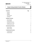
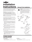
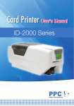
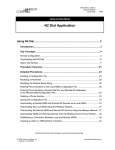
Metasys Network Technical Manual 636
Function Modules Section
Technical Bulletin
Issue Date 0793
Input Binary Frequency Function Module
Introduction
©
Page
3
•
Description
3
•
Application
4
•
Capabilities
4
•
Theory of Operation
5
•
Specifications
6
Installation Procedures
7
•
General Information
7
•
Flow Meter
8
•
Physical Installation
9
Commissioning Procedures
11
•
11
Software Verification
Troubleshooting Procedures
13
•
Troubleshooting Chart
13
•
Ordering Information
15
1993 Johnson Controls, Inc.
Order No. 636-033
1
2 Function Modules—Input Binary Frequency Function Module
Introduction
The Input Binary Frequency (IBF) Function Module is a signal
conditioning device that interfaces incoming field signals to the DCM.
The IBF senses field data, available as rapidly cycling contact closures or
input voltages, and converts the input frequency to a DC voltage for use
by the DCM.
The IBF Function Module plugs into any of the top ten slots associated
with the DCM. Figure 1 shows typical function module locations in the
NCU. A five slot panel is pictured.
Input FMs
DCMs
IB F 101
ibf101-a
H2
32K
16K
2K
512
Description
Figure 1: IBF Function Module Location
Function Modules—Input Binary Frequency Function Module
3
Application
The IBF Function Module is typically used with a flow transmitter that has
a frequency output.
Capabilities
Table 1: Capabilities
Capability
Description
Purpose
Input from Field
Field device inputs a rapidly
changing binary state. The state
can be either:
Provides interface of a rapidly
cycling signal (a frequency
signal) to the DCM.
- Contacts (closed vs open)
- Voltage (high vs low)
Input Type Switch
A two position switch selects
type of input:
- Contacts (closed vs open)
- Voltage (high vs low)
Module is easily configured for
different input types.
Input Frequency Switch
Four 2-position switches select:
Module is easily configured for
different input frequency ranges.
Output to DCM
4 Function Modules—Input Binary Frequency Function Module
1 to 512 Hz
4 to 2047 Hz
32 to 16383 Hz
64 to 32767 Hz
Module outputs DC voltage that
is proportional to the input rate of
change (frequency).
Provides direct, plug-in
connection to the DCM.
Theory of
Operation
The figure below is a simplified function diagram of the IBF Function
Module.
IBF
Field
Device
State
Analog
Voltage
Output
Sense frequency and
convert to analog output
DCM
ibf101
Figure 2: IBF Function Diagram
The process is:
●
●
●
●
A field device provides an input signal to the IBF in the form of
contact closures or high/low voltage cycles.
Manual switch selections identify the type of input (high/low voltage
or contact closures) and the frequency range of the input.
Frequency circuitry in the IBF converts the input cycle rate or
frequency into an analog voltage output.
The DCM receives the signal and converts the analog voltage value to
a digital value. This value is entered in the data file for the point
object associated with the field device input.
Function Modules—Input Binary Frequency Function Module
5
Specifications
Table 2: Specifications
Category
Specifications For Configurations
Product Code Number
FM-IBF101
Input Range
64 Hz
32 Hz
4 Hz
1 Hz
Input Threshold
High/low voltage mode
> 8 V for “ON”
Contact closure mode
< 100K ohm for “ON”
-
32767 Hz
16383 Hz
2047 Hz
512 Hz
< 2 V for “OFF”
>800K ohm for “OFF”
Input Limits
Absolute maximum input voltage: 30 VDC or RMS (non-destructive)
Input Resistance
>330K ohm (differential)
>165K ohm from each input to analog common
Input-Output
Characteristics
Linear voltage output: from 0 to 10 VDC, proportional to input frequency.
(Zero volt output at minimum frequency)
Output Range
0 to 10 VDC
Response Time
4 sec. (maximum) for full range input frequency step change
Resolution
1 Hz or 0.1%, whichever is greater, of full scale output
Accuracy
±0.5% of full scale output at 70 ±2°F (21 ± 1.1°C)
Stability
±1.0% of full scale deviation from original calibration for one year under
normal operating conditions
Thermal Effects
±0.04% of full scale per °F for 32 to 122°F
(±0.072% of full scale per °C for 0 to 50°C)
Humidity Effects
±0.02% of full scale output per % relative humidity for 10 to 90% relative
humidity
Calibration
The module is factory calibrated.
Source Power
Power is from the DCM and NCU/NEU.
Operating
Environmental
Requirements
32 to 122°F (0 to 50°C)
10 to 90% noncondensing relative humidity
86°F (30°C) maximum dew point
Storage/Shipping
Environmental
Requirements
-40 to 158°F (-40 to 70°C)
5 to 95% noncondensing relative humidity
86°F (30°C) maximum dew point
Size
0.85 in. H x 2.6 in. W x 7.0 in. L
(2.2 cm H x 6.6 cm W x 17.8 cm L)
Weight
0.5 lb. (0.22 kg)
Agency Compliance
FCC Part 15 Subpart J - Class A, UL 916, CSA C22.2 No. 205
Agency Listings
UL Listed and CSA Certified as part of Metasys®
6 Function Modules—Input Binary Frequency Function Module
Installation Procedures
When installing and connecting function modules:
●
●
follow NEC and local codes
observe maximums as specified in the specification table and in these
installation guidelines
use switches on front of module to adjust for type of input. See figure
below.
Input Type
Sw itch Setting
High/Low Voltage
Contact Closures
IB F 101
●
H2
3 2K
16K
2K
512
General
Information
ibf101
Input Frequency
64 to 32767 HZ
32 to 16383 HZ
4 to 2047 HZ
1 to 512 HZ
Sw itch Setting
32K
16K
2K
512
Figure 3: Switch Settings
Function Modules—Input Binary Frequency Function Module
7
Flow Meter
Flow
Meter
The figure below diagrams typical connections for a flow meter.
250 ft. max.
No. 18 AWG
twisted
pair
TBF
IBF
1
S e nse fre q u en cy a n d
co nve rt to a n a lo g ou tp ut.
2
O p tio n a l
A n alo g
V o lta g e
O u tp u t
DCM
6
ibfwire
TBF in left bay
of NCU/NEU
3
6
2
5
TBF in right bay
of NCU/NEU
1
4
1
4
2
5
Strip wire and insert in side face of TBF. Use
set screw in front face to secure.
Figure 4: Connections for Flow Meter IBF Applications
8 Function Modules—Input Binary Frequency Function Module
3
6
Connection
to DCM
completed through
internal connector
on end of function
module.
Physical
Installation
The following procedure for the physical installation of the Input Binary
Frequency (IBF) Function Module assumes:
Assumptions
•
NCU/NEU panel is installed.
•
Connections to field devices are complete.
•
You have engineering drawings defining details for the installation.
•
You are familiar with Metasys Network terminology, and the location
and operation of power switches.
Procedure
For each IBF Function Module in the network, perform the following
steps.
1.
Set Input Type switch for contact or voltage inputs. See Specification
section for an explanation of switch selections.
2.
Set appropriate input frequency switch for input frequency range.
Make only one input frequency selection!
3.
Refer to Figures 3 and 4 and identify the proper panel and slot number
location for this module.
4.
Open the latch and insert the module in the appropriate slot.
5.
Close latch, locking function module in place.
Function Modules—Input Binary Frequency Function Module
9
10 Function Modules—Input Binary Frequency Function Module
Commissioning Procedures
Software
Verification
Assumptions
Procedure
The following procedure for the software verification of the IBF Function
Module assumes:
•
Physical installation at the NCU/NEU panel is complete, including
NCM, DCM, FM, etc.
•
The operating software for the network has been downloaded to the
NCM controlling the panel.
•
An Operator Workstation is available.
For each IBF Function Module in the network, perform the following
steps.
1.
Select the System summary that includes this IBF object.
2.
Verify that the point object defined in the System summary, the
function module, and the field device are connected as defined by
Figure 5. Correct if necessary.
3.
Verify that the object’s Value attribute (as seen in the summary)
matches the actual value for the field device. Calibrate if necessary.
4.
If calibration is required, adjust Linearization Parameter 1 up or
down, as appropriate.
a.
Using the Focus window on an Operator Workstation, adjust
Linearization Parameter 1 for proper calibration.
b.
Enter the new linearization parameter setting in the DDL or GPL
source file.
Function Modules—Input Binary Frequency Function Module
11
12 Function Modules—Input Binary Frequency Function Module
Troubleshooting Procedures
Troubleshooting
Chart
Using the diagram in Figure 5 (next page) as a troubleshooting guide. It
applies for failures between point objects and field devices connected
through an IBF Function Module.
Function Modules—Input Binary Frequency Function Module
13
Start
Is the
Summary
containing this object
displaying correct
values?
Yes
Exit
No
Is
Point
object definition
OK?
Fix definition.
See Operator Workstation
User's Manual.
No
Yes
Is DCM
error LED off and
is N2 polling and
responding?
No
Troubleshoot DCM
See DCM 101 Technical
Bulletin .
Yes
No
Is
external power
required?
Yes
Is
external power
supply OK?
No
Repair or replace if
JCI is responsible.
Yes
Using a
scope*, check
FM input.
OK?
Yes
No
Using
a scope*, check
field device
output.
OK?
* or frequency
counter
No
Yes
Replace FM.
See Ordering Information
ordering information. Refer
to Material Return and
Allowance Program,
Procedure 3C2700
for
information on returning
defective FMs.
for
Troubleshoot
connections
and wiring.
Repair or replace field
device if JCI is responsible.
ibfflow
Figure 5: IBF Troubleshooting
14 Function Modules—Input Binary Frequency Function Module
Ordering
Information
Table 3: Code Number
Description
IBF Function Module
Product Code Number
FM-IBF101-0
Function Modules—Input Binary Frequency Function Module
15
Notes
Controls Group
507 E. Michigan Street
P.O. Box 423
Milwaukee, WI 53201
16 Function Modules—Input Binary Frequency Function Module
FAN 636
Metasys Network Technical Manual Name
Revision Date 0793
Printed in U.S.A.