1
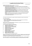
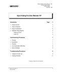
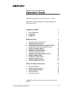
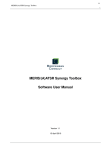
Metasys Network Technical Manual 636
Objects Section
Technical Bulletin
Issue Date 0893
Analog Output Digital (AOD) Object
Introduction
3
Quick Start
*4
●
Engineering Overview
9
●
Overview of Operation
*9
●
Command Processing
10
●
Output Processing
●
COS, Triggers, and History
21
●
Hardware Interface
24
Reference Tables
●
AOD Attribute Table
●
AOD Command Table
*19
27
*27
33
* Indicates those sections where changes have occurred since the last printing.
©
1993 Johnson Controls, Inc.
Order No. 636-082
1
2 Objects—Analog Output Digital (AOD) Object
Introduction
An Analog Output Digital (AOD) object is the software representation of
an analog output used for position control. The AOD object is generally
used with a PID Loop object.
The AOD allows for the execution of multiple commands on a priority
basis. Commands may be issued by an operator, a control process, or a
PID Loop (PIDL) object. You can view the commanded value of the
AOD in operator displays that appear on the Operator Workstation. (For
detailed information, refer to Managing Alarms and Change-of-State
Reports in the Operator’s Guide section of the Operator Workstation
User’s Manual.
Figure 1 diagrams a typical example of an AOD application. In this
example, a PIDL object is controlling the temperature in a supply duct.
The control is through two AODs. One AOD controls a heating valve and
another controls a cooling valve. The PIDL sequences between the valves
such that either the heating coil or the cooling coil is used to reach
setpoint.
Heating
Cooling
H
C
H
HWR
NC
C
C
CWR
NC
HWS
AO D
PID L
NC
C
NO
CWS
OAP
FM
AOD Object
PIDL Object
AO D
AOD Object
OAP
FM
a o d p id l
Figure 1: A PIDL Object Controlling Two AODs
Objects—Analog Output Digital (AOD) Object
3
Quick Start
This Quick Start section provides the information you need to define an
AOD object quickly. It contains:
●
●
Defining the AOD
●
●
online, using the Operator Workstation AOD object definition window
offline, using the Graphic Programming Language (GPL) data base
template
offline, using the Data Definition Language (DDL)
The AOD object can be modified:
●
●
Default Attribute
Settings
a list of the attributes that you must define for the AOD
The AOD object can be defined:
●
Modifying the AOD
the default attribute values that have been system designed for the
AOD object. There is no need to change these values, unless your
application requires different attribute definitions.
online, using the Operator Workstation AOD object focus window
offline, using the Graphic Programming Language (GPL) data base
template
Default attribute settings are available for both the online and the offline
definition methods. Default settings are the same, regardless of the
method used. When you first enter the object definition window or GPL
template, default settings are displayed in boxes to the right of the attribute
labels. Figure 2 shows the object definition window. Figure 3 shows the
GPL data base template.
4 Objects—Analog Output Digital (AOD) Object
A nalog O utput D igital D efinition [D C M140]
Item
Edit
View
Action
Help
G o To Accessory
HD Q T RS
A H U -1
B LD G -1
A H U -1
S y stem N am e
O b ject N am e
E x p an d ed ID
G r ap h ic S y m b o l #
O p e ratin g I n str . #
P a ra m eters
S p an L o w I n pu t
S p a n H ig h In p u t
S p a n L o w O utp u t
S p an H ig h O u tp u t
C o m m . D isa b led
N
H ar dwar e: D C M 1 40
S y s te m N am e
NC5
O b jec t N am e
DCM2
Po in t Ty p e
PRO P
1
S lo t N u m b er
Su b s lo t N u m b er
S te p Ra tio
S atu ratio n Size
F la g s
A uto D ia lo u t
E na b le P T H is to ry
S av e PT H is to ry
A uto R e sto re
N
Y
N
Y
E n g ineer in g D a ta
A n alo g U n its
D e cim al P o sitio n
R ep o rt T y p e
O V E R R ID E
AH U -1
0
0
PC T
1
NONE
F IG 2
Figure 2: AOD Default Values at the Operator Workstation
Object Definition Window
Note: If the point type in the Point Type field is MAO, the Subslot
Number, Step Ratio, and Saturation Size attributes have definition
boxes next to their names. Otherwise, if the point type is INCR or
PROP (the default) these attributes are undefinable and no
definition boxes appear next to their attribute names (as in
Figure 2).
Objects—Analog Output Digital (AOD) Object
5
A N A L O G O U T P U T D IG IT A L O B J E C T (A O D )
ID E N T IF I C A T I O N
PAGE 1
E N G IN E E R IN G D A TA
S y s te m N a m e
=
A n a lo g U n it s
O b je c t N a m e
=
D ec i m al P o s itio n =
E xp a n d e d ID
=
=
PCT
1
HARDWARE
S y s te m N a m e
=
O b je c t N a m e
=
H /W T y p e
=
D C M 140
S lo t N u m b e r
=
1
P o in t T y p e
=
PROP
F 1 0 - SA V E,
E SC /m o u s e c lic k - C AN C E L ,
P G D N - P AG E
A N A L O G O U T P U T D IG IT A L O B J E C T (A O D )
FLAG S
A u to D ia lo u t
PAGE 2
REP ORT TY PE
=
N
E n a b le P T H is to ry =
Y
S a v e P T H is to ry
=
N
C o m m D isa b le d
=
N
A u to R e sto re
=
Y
O ve rrid e
PARAME TERS
S p a n L o w In p u t
=
S p a n H ig h In p u t
=
S p a n L o w O u tp u t
=
S p a n L o w O u tp u t
=
F 10 - SAVE,
E S C /m o u s e clic k - C A N C E L ,
=
NONE
G r a p h ic Sy m b o l # =
0
O p e r a tin g In str. # =
0
P G U P - P AG E
F IG 3
Figure 3: AOD Default Values at the GPL Data Base Template
6 Objects—Analog Output Digital (AOD) Object
Defining Attributes
You can define the AOD object quickly by filling in the attribute fields
that are blank. These fields do not have default values. Depending on the
hardware type associated with the AOD, the attributes may vary. Table 1
lists the AOD object attributes you must define that are common to all
types of AOD objects. For a description of all attributes of the AOD for
each hardware type, refer to the Reference Tables later in this document.
Table 1: AOD Attributes With No Default Values
Changing the
Default Settings
Attribute Label
Description
Entry
System Name
Name of an existing system, such as
AHU_1 or AIR_SYS. GPL and DDL
require you to define the System Name.
8 alphanumeric characters
Object Name
Name that defines the object, such as
OSA_DMPR (for outside air damper).
The Object Name cannot already exist
under the given System Name.
8 alphanumeric characters
Expanded ID (optional)
Name that more clearly identifies the
object, such as OUTSIDE AIR
DAMPER. This field appears on the
Object Focus window, GPL template,
and summaries.
24 alphanumeric characters
Hardware System Name
Name of an existing system. It might
represent the control panel or Network
Control Module that’s handling the
object.
8 alphanumeric characters
Hardware Object Name
Name of the hardware object to which
the object is mapped. The object name
must already exist for the given
Hardware System Name.
8 alphanumeric characters
You can change any AOD attribute default value, with a single exception:
You cannot modify the System Name at the AOD Object Definition
window. To change other default values, just enter acceptable values in
the attribute fields. Data entry procedures are described in the Operator
Workstation User’s Manual.
For additional information on AOD attributes, see the rest of this
document.
●
●
The theory sections explain the interrelationship between various AOD
attributes (from an applications perspective).
The attribute description table contains an alphabetized listing of all
AOD attributes, including acceptable entries.
Objects—Analog Output Digital (AOD) Object
7
8 Objects—Analog Output Digital (AOD) Object
Engineering Overview
Overview of
Operation
Figure 4 illustrates the general operation of an AOD object. The blocks
represent functions performed by the software. AOD software operations
are summarized after the figure, and then explained in detail throughout
this document.
F u n ctio n
A ttrib u te
C h a n g e -o f-S ta te
R e p o r tin g
O ve rrid e C o m m a n d
fro m o p e ra to r
C o m m a n d ed V alu e
P ID L V a lu e
S p a nn in g
S ch e d u lin g o r
C o n tr o l P r o ce s s
C om m and
C om m a nd
P rio ritiza tio n
O u tp u t
C o n tr o l
H a rdw a re
In te rfa ce
C o n tr o l P r o ce s s
T rig g e r in g
P o in t H isto r y
F IG 4
Figure 4: AOD Functional Flow
Command
Processing
●
●
Spanning—The AOD spans the PIDL input to ensure values are
within a specified range. Upper and lower bounds (span) may be
defined for the AOD object. Span is entered as two values that set the
input range, and two values that set the output range.
Command Prioritization—The software performs a priority check to
determine the highest priority command for execution.
-
You can issue an Override command from an Operator
Workstation or NT.
-
PIDL objects usually command AODs. You can use multiple
PIDL objects to position control multiple analog devices, or use
one PIDL object to control a group of analog devices.
-
A control process can also send commands to an AOD.
Objects—Analog Output Digital (AOD) Object
9
Output Processing
COS, Triggers, and
History
●
●
●
●
Hardware Interface
Command
Processing
●
Output Control—This process determines whether the output will be
incremental or proportional.
Change-of-State (COS) Reporting—If an AOD is overridden, this
function may send a report to one or more Operator Workstations,
printers, or PC files. Operator Workstations, printers, or PC files only
receive the Override reports if they are defined as destinations in the
Report Group for the type of report specified in the filed
Report Type - Override. The NCM performs COS reporting.
Control Process Triggering—An offline condition, a change in the
AOD output, and other attribute changes can trigger (cause) a control
process to run.
Point History—Certain attributes of the AOD object may be sent to a
point history file. The NCM will hold the last ten samples.
Hardware Interface—The AOD maps to the DCM or DCM140
defined in this function.
Figure 5 is a flow diagram of AOD command processing. The blocks
represent software functions. The dashed boxes represent the attributes
that define or control the functions.
F un ctio n
A ttrib u te
O verrid e C om m a n d
fro m o p e ra tor
C o m m a n d fro m P ID L
S p a n H ig h In p u t
S p a n L o w In p u t
S pa nn ing
C o m m an d
P rioritiza tio n
O u tp u t
C o n tro l
S p a n H ig h O u tp u t
S p a n L o w O u tp u t
S c h e d u lin g o r
C o n tr o l P r o c e s s
C om m a nd
C o m m a nd e d F e ature
C o m m a n d P rio rity
FIG 5
Figure 5: AOD Command Processing Functional Flow
10 Objects—Analog Output Digital (AOD) Object
An AOD object may be commanded by:
an operator at an Operator Workstation or NT
●
a control process
●
a PID Loop object
For a detailed description of commands, refer to Table 4: Analog Output
Digital Object Commands at the end of this document. For a discussion of
how features send commands to objects, refer to the Feature Software tab
in this manual, the JC-BASIC Programmer’s Manual, and GPL
Programmer’s Manual.
●
PID Loop Input
A PID Loop (PIDL) input to the AOD is actually the output value of a
PIDL. When a PIDL commands an AOD, the PIDL output becomes the
AOD’s input.
PIDLs can command AODs to adjust Open/Close position by a percentage
of the full scale. The AOD then adjusts to the specified amount.
Spanning
The AOD object has three types of spans: Type 0, 1, and 2. The AOD
uses the span types to present more meaningful values to the operator.
Another reason span types are used is so you don’t have to take into
account the actual span limits when commanding the AOD.
How Spanning Works
There are four Span attributes. They work as a set to define a range (or
span) for PIDL output values. To initiate spanning on a particular AOD,
set the four Span attributes when defining the object. The first two define
the input range; the second two define the output range.
For the PIDL input to the AOD, the Span equation:
●
●
determines the minimum and maximum input allowed at the AOD
produces an output proportional to the input
Attributes You Set for Spanning
Four attributes affect Spanning:
Span Low Input
●
Span High Input
●
Span Low Output
●
Span High Output
Enter a value for each range according to your application. Decimal or
nondecimal values are acceptable. There are no upper or lower limits,
although each value must be unique. Also, the Span High Input value
must be greater than the Span Low Input value. To disable the Span
function, leave all four attribute values blank.
●
Objects—Analog Output Digital (AOD) Object
11
For an example on setting span limits, let’s assume you are setting the
span for the example diagrammed in Figure 7. For the heating AOD,
define the span attributes as follows:
●
Span Low Input
0%
●
Span High Input
100%
●
Span Low Output
0%
●
Span High Output
100% (fully closed)
(fully open)
Once values are set for the span input and output ranges, the software
performs the following algorithm:
●
input analog value = analog input to be spanned
●
output analog value = the output of the span function
1. IF input analog value > span high input,
THEN output analog value = span high output
2. IF input analog value < span low input,
THEN output analog value = span low output
3. IF span low input <= input analog value <= span high input,
THEN
m = (span high output - span low output) / (span high input - span
low input)
b
= span low output - (m)(span low input)
output analog value = (m)(input analog value) + b
Note: m = slope of the span function, b = y intercept. This algorithm is
visually described in Figure 6.
span_high_output
100
Percent
Output
span_low_output
0
0
span_low_input
100
span_high_input
PIDL
Command
FIG6
Figure 6: Input and Output Values of the Span Function
12 Objects—Analog Output Digital (AOD) Object
Span 0
Span Type 0 output span limits are 0 to 999.
Analog Output Digital
PIDL
Span
Span High Input Span High Output
Span Low Input
Span Low Output
Process, GPL,
OWS, or NT,
C om m and
Priortization
Override and
Command
Output
Control
FM
Commanded
Value
Fig789
Figure 7: Span Type 0
With the AOD Span Type 0, the signal from the PID Loop is spanned, and
then its output is converted to the appropriate signal for the function
module. (See Figure 7.) Commands from Scheduling, GPL Processes, the
Operator Workstation, or the Network Terminal (NT) are taken and
directly converted to the appropriate signal for the function module (in
terms of % full scale of the function module range).
This works well when spanning is either not required or simply reverses
the signal. The operator sees a commanded value in the range of 0% to
100% and commands the AOD to that same value.
Example
In this example, a normally closed cooling valve is used with a spring
range of 9 to 13 PSI and an FM-OAP101-0. With it, you can adjust the
zero and span of the function module to provide a 0% command when the
valve is closed and a 100% command when the valve is open. Spanning in
this example is not needed. If the controller is reverse acting instead of
direct acting, you can reverse the controlled device action by defining the
span parameters as follows:
Span Low Input = 0
Span High Input = 100
Span Low Output = 100
Span High Output = 0
Objects—Analog Output Digital (AOD) Object
13
Span Type 1
The Type 1 output span limits are 1000 to 1999.
Analog Output Digital
PIDL
Span
Span High Input Span High Output
Span Low Input
Span Low Output
Command Span
Process, GPL,
OWS, or NT
Override and
Command
1 00 S p a n H ig h O u tp u t
0
C om mand
Priortization
Output
Control
FM
S p a n L o w O u tp u t
View Span
Commanded
Value
100 S p a n H ig h O u tp u t
0
S p a n L o w O u tp u t
Fig789
Figure 8: Span Type 1
When you select Span Type 1, the commands from Scheduling, GPL
Processes, the Operator Workstation, or the NT are taken and spanned
from 0 to 100% to allow you to command the AOD in easily
understandable values. (See Figure 8.)
The command that is sent to the device is also spanned from 0 to 100% to
provide an understandable display to the operator and for use in processes.
The PID Loop is spanned the same way that it was with Span Type 0.
Example
In this example, the function module is an FM-OAE101-0 connected to an
FM-OAP103-0. This combination provides 0 PSI with a 0% command
and 20 PSI with a 100% command. If the actual control device is a
normally closed cooling valve with a spring range of 9 to 13 PSI, a span
with the following parameters is needed:
Span Low Input = 0
Span High Input = 100
Span Low Output = 1045
Span High Output = 1065
This works well for the PID Loop (direct acting). It saturates at 100%
when the valve is fully open and saturates at 0% when the valve is fully
closed. You see 0% CLG when the valve is closed and 100% CLG when
the valve is open. A command from Scheduling, GPL, the OT, or NT is
spanned using the same span output limits as the PID Loop. A command
of 50% from any source is spanned to 55% and then sent to the actual
device. A command of 100% is spanned to 65% and so forth.
14 Objects—Analog Output Digital (AOD) Object
Span Type 2
The span output limits for Span Type 2 are 2000 to 2999. This type
provides an inverse-acting version of Span Type 1.
Analog Output Digital
PIDL
Span
Span High Input Span High Output
Span Low Input
Span Low Output
Command Span
Process, GPL,
OWS, or NT
Override and
Command
0 S p a n H ig h O u tp u t
C om m and
Priortization
Output
Control
FM
1 0 0 S p a n L o w O u tp u t
View Span
Commanded
Value
0
S p a n H igh O u tp u t
100
S p a n L o w O u tp u t
Fig789
Figure 9: Span Type 2
When you select AOD Span Type 2, the commands from Scheduling, GPL
Processes, the Operator Workstation, or the NT are taken and spanned
from 100 to 0% to allow the operator to command the AOD in easily
understandable values. See Figure 9. The command that is sent to the
device is also spanned from 100 to 0% to provide an understandable
display to the operator and for use in processes. The PID Loop is spanned
the same way that it was with an AOD Span Type 0.
Example
In this example, the function module is an FM-OAE101-0 that is
connected to an FM-OAP103-0. This combination provides 0 PSI with a
0% command and 20 PSI with a 100% command. If the actual control
device is a normally open cooling valve with a spring range of 3 to 6 PSI,
a span with the following parameters is needed:
Span Low Input = 0
Span High Input = 100
Span Low Output = 2015
Span High Output = 2030
This works well for the PID Loop (direct acting). With Span Type 2, the
operator will see an indication of 100% HTG when the output to the
function module is the value of Span Low Output and the valve is fully
open and 0% HTG when the valve is fully closed. Scheduling, GPL
processes, the Operator Workstation, and NT can command the AOD in
the same way.
Objects—Analog Output Digital (AOD) Object
15
Determining Span Type
To determine the type of span you need, refer to the following flowchart.
Start
Set up PIDL and span
limits of AOD for
proper control
A. Are the output span limits
0% and 100% satisfactory
and
B. The choice of engineering
units satisfactory? e.g., % HTG, not % OPEN
or
C. Is this DCM at an
earlier revision
level than A.10?*
Yes
Use Span Type 0
[(A and B) or C]
No
Do you want to output the Span
Low Output (SPAN_OT1) to the
function module when you
command the AOD
to 0%?
Yes
Use Span Type 1
No
Use Span Type 2**
s p a n flo w
End
* To determine the firmware revision level of the DCM, cycle power and observe which LED stays on during
the diagnostic startup. The revision is indicated by the LED number (A.10 lights LED number 10).
** Selecting Type 2 will output the Span Low Output (SPAN_OT1) to the function module when you
command the AOD to 100%.
Figure 10: Determining Which Span Type to Use
16 Objects—Analog Output Digital (AOD) Object
Defining Span
To use AOD Span Type 0, 1 or 2, use the following equations to
determine the actual span limits to enter during AOD Object definition:
Span Low Output = (AOD Span Type x 1000) + Calculated Span Low Output
Span High Output = (AOD Span Type x 1000) + Calculated Span High Output
(Determine the Calculated Span Output limits from the PID Loop action
and the Controlled device action.)
Command
Prioritization
The AOD object supports three levels of priority for coordinating the
execution of commands requested by operators and control processes.
When a command is sent to an AOD object, a priority check is performed
to determine if the command should be executed. If a number of
commands are present at once, only the highest priority action is
performed.
For example, let’s assume a control process commanded an AOD to open
10%. At the same time, an operator issues an Override command to the
AOD to open 50%. The priority check compares the priority level of the
process against the operator Override command. Operator Override is a
higher priority, so the AOD is overridden to the operator specified value.
Attributes Associated With Command Prioritization
Five attributes reflect the AOD command prioritization process:
●
Commanded Feature
●
Command Priority
●
Commanded Value
●
Auto Restore
●
S/W Override
Commanded Feature identifies the source of the object’s Current Value.
The source can be the operator, a control process, or a PIDL output.
Command Priority identifies the priority level of the Commanded
feature. If, for example, a control process is responsible for the new AOD
commanded value, the AOD Focus Window displays Process in the
Commanded Feature field and 2 (the priority of this command) in the
Commanded Priority field.
Commanded Value updates to reflect the new commanded value. This is
displayed at the Object Focus window.
Objects—Analog Output Digital (AOD) Object
17
Auto Restore identifies whether or not (Y or N) the AOD will act as an
auto restore object.
When defined as an auto restore object, the AOD will automatically revert
back to its last commanded condition when the:
●
●
NCM goes through a “warm start.” A warm start implies that the
NCM lost power, kept its memory, and then restarted when power
resumed.
AOD goes back online. This implies that communications were
broken and then resumed between the AOD device and the DCM.
If the AOD is defined as an auto restore object, and the NCM goes through
a warm start, the AOD issues any pending high priority command (priority
1 or 2); otherwise, it restores communication with the hardware.
If the auto restore operation is triggered by an NCM warm start,
commands are issued after the Restart process is run.
S/W Override specifies whether or not (Y or N) the object is currently in
an overridden state due to an operator Override command.
You can use the Override command to change the AOD Commanded
Value to a specific setting. Issue the Override command from an Operator
Workstation Command Action menu or from an NT.
How Command Prioritization Works
Each AOD has its own object record. This record contains a priority table
that serves three purposes. It:
●
●
●
lists the priority levels of commands
keeps track of command requests, and performs a priority check to
determine which command should be executed
records which operator command or software feature currently controls
the object
Table 2 describes the three priority levels.
Table 2: AOD Command Priority Levels
Priority Level
Command Sources
1
Operator entered override
2
Set AOD and Release AOD issued by operator or control process. Must be
released before Level 3 command can be issued.
3
PIDL control
18 Objects—Analog Output Digital (AOD) Object
Output Processing
Figure 11 is a flow diagram of AOD output processing. The blocks
represent software functions. The dashed boxes represent the attributes
that define or control the functions.
F u n ctio n
A ttrib u te
P o in t T y p e
S te p R a tio
S a tu r a tio n S iz e
H /W O v e r rid e
O u tp u t
C o n tro l
Commanded Value
C om m a nd
P rio ritiza tio n
fig8
Figure 11: AOD Output Processing Functional Flow
Output Control
Output Control tells the DCM what type of hardware connects to the
AOD. The hardware type determines whether the final output will be
incremental or proportional.
Proportional output is a percent of full scale. It is used by true analog
output digital objects. It takes the output from the span function and runs
it through a fixed span that has 0 to 100 as the input range and 0 to 4095 as
the output range. The function module to which the AOD is mapped then
converts the output to the appropriate signal, based on the module type.
For other important information, refer to the Spanning section.
Multiple analog output (MAO) uses the Output Analog Function Module
(OAN101). This type of output provides proportional output for either
one or two independent analog outputs, and is valid for the DCM140 only.
Incremental output uses the OBE and OTE function modules. This output
provides either a positive or negative pulse for a duration, which drives an
output device to adjust to some percentage of the full scale. For other
important information, refer to the Spanning section.
Attributes Associated with Output Control
Three attributes determine the final output:
●
Point Type
●
Step Ratio
●
Saturation Size
Objects—Analog Output Digital (AOD) Object
19
Point Type is the type of hardware output. PROP is proportional. INCR
is incremental. MAO is multiple analog output and implies a proportional
output (valid for the DCM140 only).
The Step Ratio attribute relates only to incremental point types. This
value defines the duration of the pulse generated by the incremental analog
output hardware. The units are in seconds per percent.
For example:
Step Ratio ..........................................0.9 seconds/percent
Previous Position ...............................50%
New Commanded Position ................40%
The pulse generated by the output would be:
Output Pulse ......................................= 0.9 * (40 - 50) = -9 seconds
Direction ...........................................= sign of the difference between
the new commanded position
and the previous position
The Saturation Size is the pulse duration in seconds used to
resynchronize the hardware point at 0% or 100%. This attribute applies
only for incremental Point Types.
The H/W Override attribute on the AOD Object Focus window signals
that a hardware switch has overridden the object’s Commanded Value.
20 Objects—Analog Output Digital (AOD) Object
COS, Triggers, and
History
Figure 12 is a flow diagram of AOD triggers and history. The blocks
represent software functions. The dashed boxes represent the attributes
that define or control the functions.
F u n ctio n
A ttrib u te
R e po rt Typ e
O ve r r id e
R e p o rts L o c ke d
C h a n g e - o f- S ta te
R e p o r tin g
A u to D ia l-U p
R e p o rt T yp e
O ve rr id e
C o n tr o l P r o ce s s
T rig g e r in g
E n a b le P o in t
H isto ry
P o in t
H isto r y
S a v e P o in t
H isto r y
fig 1 2
Figure 12: AOD Triggers and History Functional Flow
COS Reporting
A detailed explanation of Change-of-State (COS) reporting is contained in
the Report Router/Alarm Management Technical Bulletin, under the
Feature Software tab of this manual. A brief discussion of this topic
follows.
When the AOD object is overridden, a COS report can be sent to one or
more devices, including an Operator Workstation screen or file, NCM
printer, and Operator Workstation printer.
Attributes You Set for COS Reporting
Three attributes affect COS Reporting:
●
Report Type Override
●
Report Locked
●
Auto Dial-out
Objects—Analog Output Digital (AOD) Object
21
Report Type Override represents the COS report that is generated when
you set the AOD commanded value with the Override command or
manually override the function module. For this attribute, you specify one
of the following report types:
●
None
●
Crit1
●
Crit2
●
Crit3
●
Crit4
●
Follow-Up
●
Status
Report Access Group definition for Report types determines the
destination change-of-state reports. Follow-Up and Status reports can be
sent to either a printer or PC file. For example, all Follow-Up reports
could go to an NCM printer. Critical reports can be sent to either a printer,
PC file, or Operator Workstation screen. In addition, higher priority
Critical reports are displayed at Operator Workstations before lower
priority reports (e.g. Crit 1 is displayed before Crit 2). If a lower priority
report is presently displayed on the screen, a higher priority Critical report
will not override it. If you specify None, the Report Router will not cause
a report to be sent to an operator device when a COS occurs. If you
specify None, the COS will not cause a report to be sent to an operator
device.
Reports Locked specifies whether or not (Y or N) the object sends COS
reports to operator devices. You can stop and start reports using the Lock
Reports and Unlock Reports commands. The Reports Locked attribute
merely signifies which command is currently in effect.
Auto Dial-out specifies whether or not (Y or N) Critical reports (Crit1 to
Crit4) force a dial-up to a remote Operator Workstation.
Triggering Control
Processes
Certain attributes of the AOD object can trigger a control process. This
means that when the value of an AOD triggerable attribute changes, it can
cause a control process to run. Triggerable attributes of the AOD include:
●
Object Offline
●
H/W Override
For further information on triggers, refer to the Software Architecture
section of this manual, the JC-BASIC Programmer’s Manual, or the
GPL Programmer’s Manual.
22 Objects—Analog Output Digital (AOD) Object
Attributes You Set for Triggering Control Processes
One attribute affects the triggering of control processes:
Triggers Locked specifies whether or not (Y or N) the object can trigger a
control process. Triggers can be stopped and started using the Lock
Triggers and Unlock Triggers commands. The Triggers Locked attribute
specifies which command is currently in effect.
Point History
The Point History feature samples, displays, and archives certain attributes
associated with the AOD object. Samples are temporarily stored in a point
history record at the NCM where the AOD is defined. This record is
automatically added when the object is added, and deleted when the object
is deleted. The record is a “circular buffer,” meaning that it’s a fixed size
in which the oldest data samples are replaced with the newest samples. It
will hold the last ten history samples for a specific AOD object. Data in
this circular buffer can be uploaded automatically to an Operator
Workstation for long-term storage.
Point History takes samples of these attributes whenever they change:
●
Commanded Value (no sample taken if commanded by PIDL)
●
Commanded Feature (no sample taken if commanded by PIDL)
●
S/W Override
●
H/W Override
●
Object Offline
●
Comm Disabled
●
time and date of each occurrence
Since the PIDL can take many samples within a very short time (e.g., one
sample per second), a sample is not taken each time the PIDL commands
the value or feature.
Attributes You Set for Point History
When defining the AOD object, you may set two attributes relating to
point history:
●
Enable Point History
●
Save Point History
Enable Point History specifies whether or not (Y or N) historical
information is collected automatically at the NCM for this object. This
collection begins as soon as the object is defined.
Objects—Analog Output Digital (AOD) Object
23
Save Point History specifies whether or not (Y or N) historical
information for the object is sent automatically from the NCM to an
archive file on an Operator Workstation. If you select N, the information
is only buffered at the NCM, and will be overwritten with new data when
the buffer fills up.
Hardware Interface
The AOD object can map to either a DCM or a DCM140.
Mapping means:
●
●
The analog output device is connected to a specific place on a specific
controller.
This place is referenced in software so that the AOD object knows
where to: (1) receive input signals, and (2) issue output commands.
Figure 13 is a flow diagram of the AOD hardware interface. The blocks
represent software functions. The dashed boxes represent the attributes
that define or control the functions.
F u n ctio n
H a r d w a r e S ys te m
Nam e
DCM
H a rd w a re O b je ct
Name
A ttrib u te
H a rdw a re
In te rfa ce
S lo t N u m b e r
H a r d w a r e S ys te m
Nam e
H a rd w a re O b je ct
Name
DCM140
S lo t N u m b e r
S u b slo t N u m b e r
fig 1 3
Figure 13: AOD Hardware Interface
This section explains the attributes you’ll use to establish the hardware
interface between the AOD and the appropriate hardware device.
The following attributes are common to both devices:
•
Hardware System Name
•
Hardware Object Name
•
Slot Number
24 Objects—Analog Output Digital (AOD) Object
Mapping to a DCM
The AOD maps to any one of the ten universal outputs on the Digital
Control Module (DCM). The DCM converts digital counts to an analog
value that is output to the function module, which produces the
appropriate electrical or pneumatic output. See the Control Modules and
Function Modules sections of this manual for additional DCM and FM
information.
Attributes Linking the DCM with the AOD Object
Three attributes link the AOD and the DCM:
●
Hardware System Name
●
Hardware Object Name
●
Slot Number
Hardware System Name must be of an existing system, such as
FLOOR1. It might represent the control panel or NCM that’s handling the
AOD. Enter up to eight ASCII alphanumeric characters. There is no
default setting.
Hardware Object Name is the name of the DCM that the object is
mapped to. This object must be already defined. If it is not defined,
define it before you define the AOD. Enter up to eight ASCII
alphanumeric characters. There is no default setting.
Slot Number identifies the function module slot (1 through 10) where the
AOD device is connected. The AOD is actually wired to a terminal on the
terminal strip. This terminal is electrically connected to a specific FM
slot. Enter a value from 1 through 10. The default is 1.
Objects—Analog Output Digital (AOD) Object
25
Mapping to a
DCM140
The AOD maps to any one of the 20 universal outputs on the DCM140.
The DCM140 converts digital counts to an analog value that is output to
the Output Analog function module (OAN101), which produces the
appropriate electrical or pneumatic output. See the Control Modules and
Function Modules sections of this manual for additional DCM140 and
OAN101 information.
Attributes Linking the DCM140 With the AOD Object
Four attributes link the AOD and the DCM140:
●
Hardware System Name
●
Hardware Object Name
●
Slot Number
●
Subslot Number
Hardware System Name must be of an existing system, such as
FLOOR1. It might represent the control panel or NCM that’s handling the
AOD. Enter up to eight ASCII alphanumeric characters. There is no
default setting.
Hardware Object Name is the name of the DCM140 that the object is
mapped to. This object must be already defined. If it is not defined,
define it before you define the AOD. Enter up to eight ASCII
alphanumeric characters. There is no default setting.
Slot Number identifies the function module slot (1 through 10) where the
AOD device is connected. The AOD is actually wired to a terminal on the
terminal strip. This terminal is electrically connected to a specific FM
slot. Enter a value from 1 through 10. The default is 1.
Subslot Number represents the OAN101 Output Analog function module
subslot where the AOD device is connected. The AOD is actually wired
to a terminal on terminal strips. This terminal is electrically connected to
a specific OAN101 subslot. Enter a value from 1 to 2. The default is 1.
26 Objects—Analog Output Digital (AOD) Object
Reference Tables
AOD Attribute
Table
This section lists the attributes of the AOD object. This information may
be helpful for control process programming and object definition. This
page contains a description of terms used in the table.
S/W Name
Column heading. (Software name) The name of each attribute as it is recognized
by the Metasys software.
PMI Label
Column Heading. The name of each attribute field as it is appears in the Metasys
windows and dialog boxes.
Description
Type/Range
Column Heading. A definition of each attribute.
- String
- Boolean
- Integer
- Floating point
Code/Default
Value
ASCII alphanumeric characters, such as System/Object name
Column heading. The type of characters used and the definition limits for defining
each attribute. (Integer has a set range of numbers that can be used. Boolean
calls for either a 0 or a 1. String can be a mixture of numbers and text.
0 or 1, with 0 and 1 representing “logical states,” such as true and false
Whole numbers from -32767 to +32767, such as 22
Values that contain decimal points, such as 67.5
Column Heading. The default value for each attribute (in brackets) if a default
value exists. The meaning of each value may also be given. The Code/Default
Value column shows numbers and ASCII text. The numbers are used when
defining the object in DDL, and the ASCII text is used when defining the object
online or through GPL.
For example:
- []
Usage
0 = N = unlatched
where:
0 is used in DDL
N is used in GPL and online
Default. The value in brackets appears in the attribute field when you first enter the
Object Definition window. This remains the attribute value until you change it.
Column heading. Lists possible uses for each attribute. The following eight items
are uses listed within the Usage column:
- Definable
Means that you can set a value for the attribute, using the Data Definition
Language (DDL), Graphic Programming Language (GPL), or online Object
Definition window. You designate attribute values when defining the object.
- Writable
Means you can modify the attribute, using the Object Focus window or GPL
Template.
- Object Default
A timesaving function used in JC-BASIC programming. Allows you to omit the
attribute name when writing the logic. When omitted, the attribute name is
assumed by the program.
- JC-B Writable
- Triggerable
- Range Check
Means a JC-BASIC process can modify (write to) an attribute.
- GPL Menu
- PMI
Means the attribute is available in the GPL process Connection menu.
Means the attribute can cause (trigger) a control process.
Means the software verifies that JC-BASIC has correctly written to (modified) the
attribute.
Means the attribute value is shown in the Object Focus window.
Objects—Analog Output Digital (AOD) Object
27
Table 3: Analog Output Digital Object Attributes
Attribute
Software
PMI
Name
Label
Description
Type/
Range
Code/
[Default Value]
Usage
CMD_PRI
Command
Priority
Identifies the priority level of the
Commanded feature. The
Commanded feature is responsible for
the object’s Current Value or
Commanded Value.
integer/ 1
to 3
(3)
DIAL_UP
Auto Dial-out
Auto Dial-out specifies whether or not
(Y or N) Critical reports (Crit1-Crit4)
force a dial up to a remote Operator
Workstation.
Boolean/
0 to 1
(0=no)
1=yes
DISPLAY
ASCII
Representation Value
Indicates the object Current or
Commanded Value converted to
ASCII text for PMI display.
string/
8 char
max.
FEATURE
Commanded
Feature
Identifies the source of the object’s
Current Value or Commanded Value.
Besides features, sources can be the
operator or a control process.
Sources are listed in the Code/Default
column to the right.
Initial = Initial Value attribute, and
Shared = Sampled attribute.
integer
FORMAT
Decimal
Position
Specifies the number of digits to be
displayed to the right of the decimal
point. For example, a decimal
position of “2” would display the
number 72 as “72.00.” This
parameter applies to all floating point
attributes of the object.
integer/
0 to 3
[1]
Definable,
Writable
GRAPHIC
Graphic
Symbol #
Identifies the particular graphic
symbol used to represent the object in
Operator Workstation graphic
summaries. A value of zero means
no graphic will be displayed.
integer/
0 to
32767
[0=none]
JC-B
Writable,
Definable,
Writable,
Range
Check
HISTORY
Enable PT
History
Specifies whether or not (Y or N)
historical information is automatically
collected at the NCM for this object.
This collection begins as soon as the
object is defined.
Boolean/
0 or 1
0=no
[1=yes]
Definable,
Writable
HOA
Hardware
Override
Signals that a hardware switch has
overridden the object’s Commanded
Value.
Boolean/
0 or 1
[0=no/auto]
1=yes/manual
GPL Menu,
Triggerable
HW_OBJCT
Hardware
Object Name
Identifies the name of the hardware
object that the object is mapped to.
The name must already exist for the
given Hardware System Name.
string/
8 char.
max.
Continued on next page . . .
28 Objects—Analog Output Digital (AOD) Object
JC-B
Writable,
Definable,
Writable
PMI Display
1=Operator
3=Process
[7=DCM]
8=Override
Definable
Attribute (Cont.)
Software
PMI
Name
Label
Description
Type/
Range
Code/
[Default Value]
Usage
HW_SYSTM
Hardware
System
Name
Identifies the name that represents
the control panel or Network Control
Module that’s handling the object.
string/
8 char.
max.
INSTRUCT
Operating
Instruction #
Identifies the particular text provided
when Help is requested at the
Operator Workstation. A value of
zero means no message will be
displayed.
integer/
0 to
32767
NAME
Expanded ID
Identifies the object more clearly. For
example, Outside Air Temperature for
OAT. It appears on the Object Focus
window, GPL template, and
summaries.
string/
24 char.
max.
Defined,
Writable
OBJECT
Object Name
Defines the object, such as
AIR_FLOW (airflow switch). The
name cannot already exist under the
given system name.
string/ 8
char max.
Definable
OFFLINE
Object
Offline
Specifies whether or not (Y or N) the
object is offline. An object is
considered offline when there is a
communication break between the
object and its associated DCM.
Boolean/
0 or 1
0=Online
1=Offline
GPL Menu,
Triggerable
OVERRIDE
S/W
Override
Specifies whether or not (Y or N) the
object is currently in an overridden
state due to an operator Override
command.
Boolean/
0 or 1
[0=no]
1=yes=override
GPL Menu
OVR_RPT
Report Type
Override
Specifies the type of COS report
that’s generated when you have set
the current value with the Override
command, manually overridden the
function module, or issued an Auto
command.
integer/
0 to 6
[0=no report]
1=critical 1
2=critical 2
3=critical 3
4=critical 4
5=followup
6=status
JC-B
Writable,
Definable,
Range
Check,
Writable
PREFIX
“*” Condition
(NT only) Indicates if the object is
offline, manually overridden, hardware
overridden, trigger locked, report
locked, or disabled.
Boolean/
0 or 1
0=no
1=yes=offline, or
overridden, or . . .
PMI Display
PT_TYPE
Point Type
Identifies the kind of output provided
by the associated field device.
integer/
0, 1, or 2
[0=proportional]
1=incremental
2=Multiple Analog
Output (MAO)
Definable
MAO is a valid point type for the
DCM140 only. If MAO is used, the
function module must be the
OAN101 function module.
Definable
[0=none]
JC-B
Writable,
Definable,
Range
Check,
Writable
Continued on next page . . .
Objects—Analog Output Digital (AOD) Object
29
Attribute (Cont.)
Software
PMI
Name
Label
Description
Type/
Range
Code/
[Default Value]
Usage
REPORT
Reports
Locked
Specifies whether or not (Y or N) the
object sends COS reports to operator
devices. Reports can be stopped and
started using the Lock Report and
Unlock Report commands,
respectively. The Reports Locked
attribute merely signifies which
command is currently in effect.
Boolean/
0 or 1
[0=N=unlocked]
1=Y=locked
RESTORE
Auto Restore
Specifies whether or not (Y or N) an
object will revert to its last
commanded condition when
communication is resumed (after a
failure), or when the NCM is restarted.
Boolean/
0 or 1
0=no
[1=yes]
JC-B
Writable,
Definable,
Writable
SAT
Saturation
Size
Resynchronizes the hardware point at
0% or 100% by pulsing the point for a
calculated duration in seconds. This
attribute applies only for incremental
type points.
integer/
0 to 255
n=time in seconds
[0]
JC-B
Writable,
Definable,
Range
Check,
Writable
SAVE_HIS
Save PT
History
Specifies whether or not (Y or N)
historical information for the object is
automatically sent from the NCM to
an archive file on an Operator
Workstation. If N is selected, the
information is only buffered at the
NCM, and will be overwritten with new
data when the file fills up.
Boolean/
0 or 1
(0=N=enabled)
1=Y=disabled
Definable,
Writable
SCAN
Comm
Disabled
Specifies whether or not (Y or N)
communication is disabled between
the object and its associated DCM.
When an object is Comm Disabled, it
can’t trigger control processes, send
COS reports to operator devices, or
accept commands (except for
Enable). The Comm Disable attribute
also signifies whether the Comm
Enable or Comm Disable command is
in effect.
Boolean/
0 or 1
(0=no)
1=yes
Definable
SLOT
Slot Number
Represents the Function Module slot
where the field device is connected.
Note: Electronic field devices are
actually wired to terminal blocks
(TBFs) that are electrically connected
to a specific FM slot.
integer/
1 to 10
n=FM
slot number
[1]
Definable
Continued on next page . . .
30 Objects—Analog Output Digital (AOD) Object
Attribute (Cont.)
Software
PMI
Name
Label
Description
Type/
Range
Code/
[Default Value]
Usage
SPAN_IN1
Span Low
Input
Refer to Span High Input.
float. pt/
blank or
any
value
[Blank=disabled]
Definable,
Writable
SPAN_IN2
Span High
Input
Helps define a range (or span) for
input values and a range for output
values. Span High Input is one of
four parameters that work as a set.
Given any input value, the span
equation:
• determines the input’s position
relative to the input range
• produces an output in the same
position relative to the output
range
float. pt/
or any
value or
blank
[Blank=disabled]
Definable,
Writable
SPAN_OT1
Span Low
Output
Refer to Span High Input.
float. pt/
blank or
any
value
[Blank=disabled]
Definable,
Writable
SPAN_OT2
Span High
Output
Refer to Span High Input.
float. pt/
blank or
any
value
[Blank=disabled]
Definable,
Writable
STATDISP
Prefix
The status of the AOD object
integer/
0=[blank-normal]
2=RPT-reports locked
3=TRG-triggers locked
7=ALM-Alarm
PMI
Display
0-15
10=SWO-software override
11=HWO-software override
12=DIS-communications
disabled
14=UNR-unreliable
15=OFF-offline
STEP
Step Ratio
Provides a conversion factor used for
incremental type points. The factor
converts a Commanded Value
change in % to a pulse duration in
seconds.
float. pt/
any
value
[0.9]
JC-B
Writable,
Definable,
Writable
SUB_SLOT
Subslot
For the DCM140 only. The Output
Analog function module slot where
the field device is connected.
Integer/
1 or 2
n=DCM140 slot number
[1]
Definable
Continued on next page . . .
Objects—Analog Output Digital (AOD) Object
31
Attribute (Cont.)
Software
PMI
Name
Label
Description
Type/
Range
Code/
[Default Value]
SYSTEM
System
Name
Identifies the name of an existing
system in the network, such as AHU1.
string/
8 char.
max.
TRIGGER
Trigger
Locked
Specifies whether or not (Y or N) the
object can trigger control processes.
Triggers can be stopped and started
using the Lock Trigger and Unlock
Trigger commands. The Trigger
Locked attribute merely signifies
which command is currently in effect.
Boolean/
0 or 1
[0=N=unlocked]
1=Y=locked
UNITS
Analog
Engineering
Units
Helps make the Commanded Value
more meaningful (optional). The
units, if defined, are displayed with
the Current Value at the Object Focus
window, NT screen, and object
summaries. For example, the Current
Value can be displayed as 73.6°F, 20
PSI, 45% RH, 310 GPM.
string/
6 char.
max.
(PCT)
VALUE
Commanded
Value
Reflects the current commanded
condition of the hardware. This is
updated and displayed on the Object
Focus window. For example, the
Commanded Value field could show
50.0.
float. pt
32 Objects—Analog Output Digital (AOD) Object
Usage
Definable
(PMI default:
Current
system at
Definition
Window)
Definable,
Writable
Object
Default,
GPL Menu,
AOD Command
Table
Note: Commands to the AOD generally are not executed when the object
is offline or when communications are disabled. Offline means
there is a physical communication break between the AOD and its
associated controller. Disabled communications means an operator
used the Disable command to halt communications.
Commands are executed when the AOD is offline or disabled in
these situations: 1) the Override and Auto commands are allowed
when the object is offline, and 2) the Enable command is allowed
when the object is Disabled.
Table 4: Analog Output Digital Object Commands
S/W
Name
Command
PMI
Label
Description
Parameters
Control
Process
[Priority]
Source
PMI
[Priority]
Feature
[Priority]
AUTO
Auto
Releases the Override command, and
either resumes input/output processing
between the field and NCM, or allows
the next highest priority command to
take control of the object. Auto is an
abbreviation for automatic mode of
operation.
None
N.A.
OWS
[1]
NT
[1]
N.A.
DISABLE
Comm.
Disable
Stops the object from triggering control
processes, sending COS reports to
operator devices, and accepting
commands (except for Comm.
Enable).
None
N.A.
OWS
NT
N.A.
ENABLE
Comm.
Enable
Allows the object to trigger control
processes, send COS reports to
operator devices, and accept
commands.
None
N.A.
OWS
NT
N.A.
LOC_REP
Lock
Reports
Stops the object from sending COS
reports to operator devices. The
current state of the “locked” attributes
are saved and compared to their state
later when the object is unlocked to
determine if a report should be sent.
None
GPL
JC-BASIC
OWS
Scheduling
LOC_TRG
Lock
Trigger
Prevents the object from triggering any
control processes. This applies to all
triggerable attributes of the object.
None
GPL
JC-BASIC
OWS
Scheduling
OVERRIDE
Override
Allows the operator to replace the
current value for the object with a
user-defined value.
Value
N.A.
OWS
[1]
NT
[1]
N.A.
• Analog object examples: 50°F, 60%
RH, or 250 GPM.
• Override is highest priority, 1.
This is a manual command, only
available to operators at the Operator
Workstation or the Network Terminal.
Continued on next page . . .
Objects—Analog Output Digital (AOD) Object
33
Command (Cont.)
S/W
PMI
Name
Label
Description
Parameters
Control
Process
[Priority]
Source
PMI
[Priority]
Feature
[Priority]
RELEASE
Release
Clears an object value set by a Priority
2 command.
None
GPL
(2)
JC-BASIC
(2)
N.A.
N.A.
SET_AOD
Set AOD
Defines a value for an AOD. This
command overrides PIDL commands
(Priority 3) to the AOD.
Value
GPL
(2)
JC-BASIC
(2)
N.A.
N.A.
UNL_REP
Unlock
Report
Allows the object to send COS reports
to the operator devices. The current
state of the “unlocked” attributes is
compared to the state when the
attributes were locked to see if COS
reporting is required.
None
GPL
JC-BASIC
OWS
Scheduling
UNL_TRG
Unlock
Trigger
Allows the object to trigger control
processes. This applies to all
triggerable attributes of the object.
Unlocking triggering will cause all
triggerable attributes of the object to
report.
None
GPL
JC-BASIC
OWS
Scheduling
34 Objects—Analog Output Digital (AOD) Object
Notes
Objects—Analog Output Digital (AOD) Object
35
Notes
Controls Group
507 E. Michigan Street
P.O. Box 423
Milwaukee, WI 53201
36 Objects—Analog Output Digital (AOD) Object
FAN 636
Metasys Network Technical Manual
Release 5.02
Printed in U.S.A.