1
UM0285
User guide
EK3LV02DL
Evaluation Kit
Introduction
The EK3LV02DL is an Evaluation Kit designed to provide to the user a complete, ready-touse platform for the evaluation of the LIS3LV02DL, a low-power 3-Axis linear accelerometer
with digital output that includes a sensing element and an IC interface able to take
information from the sensing element and to provide the measured signal to the external
world.
Besides the MEMS sensor, the evaluation board mounts an ST7-USB microcontroller which
acts like a bridge between the sensor and the personal computer on which it is possible to
run either a Graphical User Interface delivered with the kit itself or dedicated SW routines
that implements customized applications.
This user manual describes the HW composing the evaluation kit and gives the informations
required to install and to run the evaluation kit user interface.
For any detail about the features implemented by the LIS3LV02DL sensor refer to
LIS3LV02DL datasheet and to the Application Note AN2381
September 2006
Rev 1
1/32
www.st.com
Contents
UM0285
Contents
1
Evaluation kit description . . . . . . . . . . . . . . . . . . . . . . . . . . . . . . . . . . . . . 6
2
EK3LV02DL GUI installation . . . . . . . . . . . . . . . . . . . . . . . . . . . . . . . . . . . 8
3
2.1
PC system requirements . . . . . . . . . . . . . . . . . . . . . . . . . . . . . . . . . . . . . . 8
2.2
Software installation . . . . . . . . . . . . . . . . . . . . . . . . . . . . . . . . . . . . . . . . . . 8
2.3
Hardware installation . . . . . . . . . . . . . . . . . . . . . . . . . . . . . . . . . . . . . . . . . 9
Graphical User Interface . . . . . . . . . . . . . . . . . . . . . . . . . . . . . . . . . . . . . 12
3.1
Connecting to Virtual the COM port . . . . . . . . . . . . . . . . . . . . . . . . . . . . . 13
3.2
Registers Read/Write . . . . . . . . . . . . . . . . . . . . . . . . . . . . . . . . . . . . . . . . 13
3.3
Direction detection demo . . . . . . . . . . . . . . . . . . . . . . . . . . . . . . . . . . . . . 13
3.4
Data Acquisition . . . . . . . . . . . . . . . . . . . . . . . . . . . . . . . . . . . . . . . . . . . . 15
3.5
3.4.1
Single Acquisition mode . . . . . . . . . . . . . . . . . . . . . . . . . . . . . . . . . . . . 15
3.4.2
Continuos Acquisition mode . . . . . . . . . . . . . . . . . . . . . . . . . . . . . . . . . 15
About_EK . . . . . . . . . . . . . . . . . . . . . . . . . . . . . . . . . . . . . . . . . . . . . . . . . 19
4
Data acquisition quick start . . . . . . . . . . . . . . . . . . . . . . . . . . . . . . . . . . 21
5
EK lite . . . . . . . . . . . . . . . . . . . . . . . . . . . . . . . . . . . . . . . . . . . . . . . . . . . . 22
6
MEMS pointer . . . . . . . . . . . . . . . . . . . . . . . . . . . . . . . . . . . . . . . . . . . . . 23
6.1
7
2/32
GUI description . . . . . . . . . . . . . . . . . . . . . . . . . . . . . . . . . . . . . . . . . . . . 23
6.1.1
Right Side: Main Controls . . . . . . . . . . . . . . . . . . . . . . . . . . . . . . . . . . . 24
6.1.2
Left Side: Pointer Application Controls . . . . . . . . . . . . . . . . . . . . . . . . . 24
Supported commands . . . . . . . . . . . . . . . . . . . . . . . . . . . . . . . . . . . . . . 25
7.1
Getting Started . . . . . . . . . . . . . . . . . . . . . . . . . . . . . . . . . . . . . . . . . . . . . 25
7.2
Supported Commands . . . . . . . . . . . . . . . . . . . . . . . . . . . . . . . . . . . . . . . 26
7.2.1
Start command . . . . . . . . . . . . . . . . . . . . . . . . . . . . . . . . . . . . . . . . . . . 26
7.2.2
Debug command . . . . . . . . . . . . . . . . . . . . . . . . . . . . . . . . . . . . . . . . . . 26
7.2.3
Stop command . . . . . . . . . . . . . . . . . . . . . . . . . . . . . . . . . . . . . . . . . . . . 27
7.2.4
Registers read . . . . . . . . . . . . . . . . . . . . . . . . . . . . . . . . . . . . . . . . . . . . 27
7.2.5
Registers write . . . . . . . . . . . . . . . . . . . . . . . . . . . . . . . . . . . . . . . . . . . . 27
7.2.6
Single bit write . . . . . . . . . . . . . . . . . . . . . . . . . . . . . . . . . . . . . . . . . . . . 27
UM0285
Contents
7.3
7.2.7
Zon and Zoff . . . . . . . . . . . . . . . . . . . . . . . . . . . . . . . . . . . . . . . . . . . . . 27
7.2.8
Device name . . . . . . . . . . . . . . . . . . . . . . . . . . . . . . . . . . . . . . . . . . . . . 27
7.2.9
Firmware version . . . . . . . . . . . . . . . . . . . . . . . . . . . . . . . . . . . . . . . . . . 28
Quick Start . . . . . . . . . . . . . . . . . . . . . . . . . . . . . . . . . . . . . . . . . . . . . . . . 28
8
Schematic diagram . . . . . . . . . . . . . . . . . . . . . . . . . . . . . . . . . . . . . . . . . 29
9
Bill Of Material . . . . . . . . . . . . . . . . . . . . . . . . . . . . . . . . . . . . . . . . . . . . . 30
10
Revision history . . . . . . . . . . . . . . . . . . . . . . . . . . . . . . . . . . . . . . . . . . . 31
3/32
List of tables
UM0285
List of tables
Table 1.
Table 2.
Table 3.
4/32
Supported commands. . . . . . . . . . . . . . . . . . . . . . . . . . . . . . . . . . . . . . . . . . . . . . . . . . . . . 26
Bill Of Material . . . . . . . . . . . . . . . . . . . . . . . . . . . . . . . . . . . . . . . . . . . . . . . . . . . . . . . . . . 30
Document revision history . . . . . . . . . . . . . . . . . . . . . . . . . . . . . . . . . . . . . . . . . . . . . . . . . 31
UM0285
List of figures
List of figures
Figure 1.
Figure 2.
Figure 3.
Figure 4.
Figure 5.
Figure 6.
Figure 7.
Figure 8.
Figure 9.
Figure 10.
Figure 11.
Figure 12.
Figure 13.
Figure 14.
Figure 15.
Figure 16.
Figure 17.
Figure 18.
Figure 19.
Figure 20.
Figure 21.
Figure 22.
Figure 23.
Figure 24.
Figure 25.
Evaluation board block diagram . . . . . . . . . . . . . . . . . . . . . . . . . . . . . . . . . . . . . . . . . . . . . . 6
Top silk-screen for EK3LV02DL kit . . . . . . . . . . . . . . . . . . . . . . . . . . . . . . . . . . . . . . . . . . . . 7
Board photograph . . . . . . . . . . . . . . . . . . . . . . . . . . . . . . . . . . . . . . . . . . . . . . . . . . . . . . . . . 7
Software installation . . . . . . . . . . . . . . . . . . . . . . . . . . . . . . . . . . . . . . . . . . . . . . . . . . . . . . . 8
Notify icon . . . . . . . . . . . . . . . . . . . . . . . . . . . . . . . . . . . . . . . . . . . . . . . . . . . . . . . . . . . . . . . 9
Driver installation through the device manager . . . . . . . . . . . . . . . . . . . . . . . . . . . . . . . . . . 9
USB driver installation with the Hardware Update Wizard . . . . . . . . . . . . . . . . . . . . . . . . . 10
Virtual COM driver port assignment . . . . . . . . . . . . . . . . . . . . . . . . . . . . . . . . . . . . . . . . . . 11
Graphical User Interface: main window . . . . . . . . . . . . . . . . . . . . . . . . . . . . . . . . . . . . . . . 12
Registers Read/Write . . . . . . . . . . . . . . . . . . . . . . . . . . . . . . . . . . . . . . . . . . . . . . . . . . . . . 13
EK Demo Mode window . . . . . . . . . . . . . . . . . . . . . . . . . . . . . . . . . . . . . . . . . . . . . . . . . . . 14
Threshold definition . . . . . . . . . . . . . . . . . . . . . . . . . . . . . . . . . . . . . . . . . . . . . . . . . . . . . . 15
Single Data Acquisition . . . . . . . . . . . . . . . . . . . . . . . . . . . . . . . . . . . . . . . . . . . . . . . . . . . . 15
Continuos Data “Acquisition Control” . . . . . . . . . . . . . . . . . . . . . . . . . . . . . . . . . . . . . . . . . 16
Plot Data and Show Data windows. . . . . . . . . . . . . . . . . . . . . . . . . . . . . . . . . . . . . . . . . . . 16
Board Axis Definition . . . . . . . . . . . . . . . . . . . . . . . . . . . . . . . . . . . . . . . . . . . . . . . . . . . . . 17
Bar Chart . . . . . . . . . . . . . . . . . . . . . . . . . . . . . . . . . . . . . . . . . . . . . . . . . . . . . . . . . . . . . . 18
Inclinometer . . . . . . . . . . . . . . . . . . . . . . . . . . . . . . . . . . . . . . . . . . . . . . . . . . . . . . . . . . . . 18
Axis Inclination . . . . . . . . . . . . . . . . . . . . . . . . . . . . . . . . . . . . . . . . . . . . . . . . . . . . . . . . . . 18
Map Browsing . . . . . . . . . . . . . . . . . . . . . . . . . . . . . . . . . . . . . . . . . . . . . . . . . . . . . . . . . . . 19
Evaluation Kit Info and About window . . . . . . . . . . . . . . . . . . . . . . . . . . . . . . . . . . . . . . . . 20
EK3LV02DL Lite GUI . . . . . . . . . . . . . . . . . . . . . . . . . . . . . . . . . . . . . . . . . . . . . . . . . . . . . 22
MEMS Pointer Demo . . . . . . . . . . . . . . . . . . . . . . . . . . . . . . . . . . . . . . . . . . . . . . . . . . . . . 23
Axis Orientation . . . . . . . . . . . . . . . . . . . . . . . . . . . . . . . . . . . . . . . . . . . . . . . . . . . . . . . . . 24
Schematic diagram for EK3LV02DL board . . . . . . . . . . . . . . . . . . . . . . . . . . . . . . . . . . . . . 29
5/32
Evaluation kit description
1
UM0285
Evaluation kit description
The EK3LV02DL is an Evaluation Kit designed to provide the user with a complete, ready-touse platform for the evaluation of the LIS3LV02DL, a low-power 3-Axis linear accelerometer
with digital output.
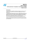
The block diagram of the evaluation kit is given in Figure 1.
Figure 1.
Evaluation board block diagram
Control Switches
(Left, Right and Reset)
MEMS
Sensor
SPI
USB
ST72F651
μC
USB
Connector
Power On LED
Data Ready LED
General Purpose LED
Besides the MEMS sensor, the evaluation board mounts an ST7-USB microcontroller which
acts like a bridge between the sensor and the personal computer on which it is possible to
run either a Graphical User Interface delivered with the kit itself or dedicated SW routines
that implements customized applications.
Few switches and LED indicators are also present to control and to monitor the functionality
of the board itself.
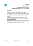
The top silk-screen of the board and the photo of the full board are shown respectively in
Figure 2 and in Figure 3.
6/32
UM0285
Evaluation kit description
Figure 2.
Top silk-screen for EK3LV02DL kit
Figure 3.
Board photograph
In order to operate the EK3LV02DL evaluation kit it is required the installation of a dedicated
driver which is delivered onto the CD accompanying the kit itself together with a GUI
interface which allows a simple interaction with the sensor itself. The steps that must be
followed to install the driver and the SW are described in the following section.
7/32
EK3LV02DL GUI installation
2
UM0285
EK3LV02DL GUI installation
The installation of Graphical User Interface (GUI) for the EK3LV02DL implies two steps:
2.1
–
the installation onto the PC of the Software delivered with the evaluation kit;
–
the installation of the Virtual COM driver needed to use the Evaluation Kit board.
PC system requirements
Both the hardware and software that compose the EK3LV02DL Evaluation Software Kit have
been designed to operate with:
2.2
–
Microsoft® Windows® XP®;
–
Microsoft.NET Framework 1.1 (or higher); this software can be downloaded for
free from the Microsoft web site (a). The installation of the “Microsoft.NET
Framework” is not required when running on windows XP SP2 or higher.
Software installation
To install the SW distributed along with the EK3LV02DL evaluation kit:
1.
Insert the MiniCD delivered with the Kit inside the CD-ROM drive
2.
If the Autorun screen does not appear, click on Start > Run, enter “D:\Autorun.exe”
and click OK. “D” represents the letter of your CD-ROM drive.
3.
Click onto “Evaluation Kit SW Installation” from the “EK3LV02DL Evaluation Kit” page
which appears;
4.
Follow the instructions given by the Installer (Figure 4).
Figure 4.
Software installation
a. http://www.microsoft.com/downloads and search for.Net framework Redistributable Package.
8/32
UM0285
2.3
EK3LV02DL GUI installation
Hardware installation
To install the virtual COM driver insert the Evaluation Kit board into a free USB port, look at
the “Notify” icon (Figure 5) and than wait for “Hardware Update Wizard”.
Figure 5.
Notify icon
If the “Hardware Update Wizard” appears as shown in Figure 7 then follow the instructions
given in Figure 7; otherwise follow the instructions indicated in Figure 6 and Figure 7.
Figure 6.
Driver installation through the device manager
Right click on My Computer
Right click on “ST MEMS UNIT” and choose for Update driver
1
2
9/32
EK3LV02DL GUI installation
Figure 7.
UM0285
USB driver installation with the Hardware Update Wizard
3
4
6
5
7
Once the installation has finished, a COM port number will be assigned to the ST Virtual
Com driver (Figure 8). The knowledge of this number is required to run the EK3LV02DL
Evaluation Software GUI. For additional details, check section 3.1.
10/32
UM0285
EK3LV02DL GUI installation
Figure 8.
Virtual COM driver port assignment
11/32
Graphical User Interface
3
UM0285
Graphical User Interface
To execute the EK3LV02DL Evaluation Software Graphical User Interface:
1.
Click on Start > All Programs
2.
Select the folder EK3LV02DL > Executables
3.
Launch the program “EK3LV02DL Ver.1.0”
With these operations the GUI main window will appear (Figure 9); the window is composed
of four main sections as detailed below:
1.
the graphical panel (ref1), where the data coming from the sensor are graphically
represented;
2.
the upper-right corner of the window (ref2), which allows to open and to close the
communication port of the PC connected to the Evaluation Kit;
3.
the right side, which contains the “Register Read/Write” and "Direction Detection
Demo" (ref3), “Single Acquisition” (ref4) and “About EK” (ref5) blocks;
4.
the bottom of the window, which handles the continuous acquisition of the acceleration
data and displays them inside the graphical panel (ref6).
Figure 9.
Graphical User Interface: main window
ref1
ref2
ref3
ref4
ref5
ref6
12/32
UM0285
3.1
Graphical User Interface
Connecting to Virtual the COM port
Before using the functions of the Evaluation Kit Software it is necessary to open the
connection with the EK3LV02DL board. This is achieved through the following procedure:
1.
Connect the EK3LV02DL to desired USB port;
2.
In the pop-menu “USB ---> Virtual COM” choose the Virtual COM number on which the
board has been mapped. For additional information on how to get this value check
section 2.3.
3.
Open the connection by clicking on “Connect” (Figure 9 ref2). Once this procedure is
completed, the General Purpose LED of the board will switch from red to green.
Once the procedure has been completed, the user can acquire, plot and save the
acceleration data measured by the sensor and he/she can access the content of the
registers embedded in the device. Further details about each single function are provided in
the sections hereafter.
Note:
Due to Virtual COM driver communication speed limits, the maximum Output Data Rate allowed for the
device is 640 Hz. Higher Output Data Rate could result in a possible data loss.
3.2
Registers Read/Write
Through the “Register Read/Write” panel (Figure 9, ref3), the user can either directly write
or read the registers value inside the LIS3LV02DL device.
In particular, by clicking on the “Read/Write” button a new window appears (Figure 10).
To perform a register read out, the user must select the desired register name into “Reg
Name” pop up menu (ref4) and then he/she must click on the “Read” button (ref2). The
result of the reading will appear in the text box “Reg Value” (ref3).
To write a data into a register, the user must select the desired register name (ref4), choose
the desired value in the text box “Reg Value” (ref3) and then click on the “Write” button
(ref1). In case of read-only registers, the write button is not enabled.
Figure 10. Registers Read/Write
3.3
ref4
ref1
ref3
ref2
Direction detection demo
The LIS3LV02DL allows the implementation of motion-controlled functions such as gaming
and terminal control while requiring reduced computational power to the application
13/32
Graphical User Interface
UM0285
controller. The device, in fact, may be programmed to generate an interrupt signal when a tilt
is detected and to return the information of the direction in which the sensor has been tilted.
With the same feature the LIS3LV02DL sensor is able to return the information about the
spatial orientation of the board without requiring the reading and the further post-processing
of the acceleration data.
This feature is demonstrated through the Direction Detection demo mode panel (Figure 11)
which is activated by clicking on the “Dir Detect” button present in the main GUI window.
Figure 11. EK Demo Mode window
ref2
ref1
ref4
ref3
ref5
In order to configure the event which will trigger the interrupt event, the user must select the
desired inner/internal and outer/external threshold (ref1), defining in this way an hysteresis
region that allows to avoid false detections and/or bouncing produced for example by either
spurious vibration or tremor. Whenever the inner thresholds is greater than the outer one,
the hysteresis region will be null and the threshold employed to detect the tilt direction will be
the outer one. A graphical representation of the internal and external thresholds is given in
Figure 12.
Whenever the absolute value of the acceleration signal measured by the sensor either
exceeds the outer threshold or returns below the inner threshold an interrupt signal will be
generated and the General Purpose green LED will blink.
If the user wants to detect the orientation changes removing the DC level of the acceleration
signal applied to the device (i.e. removing the gravity vector), it is possible to enable the High
Pass Filter embedded inside the device by acting on the “High Pass Filter” pop-up menu
(Figure 11, ref2). The cut-off frequency of the filter, which is shown inside the Cutoff
Frequency text box (ref5), is user selectable acting on the High Pass coefficients (ref3)
and on the Output Data Rate (ODR). For further details, please refer to AN2381.
To start the Direction Detection demo mode click on “Start Direction Detection” (ref4).
14/32
UM0285
Graphical User Interface
Figure 12. Threshold definition
3.4
Data Acquisition
The Data Acquisition panel is split in two sections:
3.4.1
1.
“Single Acquisition” mode (Figure 9, ref4)
2.
“Continuos Acquisition” mode (Figure 9, ref6).
Single Acquisition mode
The “Single Acquisition” mode panel allows the user to perform the measurement of the
acceleration acting on all the three axes. A single read of the acceleration data measured by
the device is done by clicking on the “Acquisition” button (Figure 13, ref1).
This panel allows also to activate and to disable the Self-Test function of the device using
the two radio buttons “Self Test ON” and “Self Test OFF” (Figure 13, ref2). Whenever the
self-test is activated, the proof mass of the sensor is electrostatically deflected and the
acceleration data measured by the sensor will exhibit a change in their DC level as specified
on the datasheet of the part. This function allows to check whether the sensor is working
properly without requiring any mechanical movement of the board mounting the sensor
itself.
Figure 13. Single Data Acquisition
ref2
ref1
3.4.2
Continuos Acquisition mode
The section related to “Continuos Acquisition” allows the user to perform a sequence of
acquisitions, to plot and to save the acquired acceleration data under different formats.
In order to start and to stop the data acquisition (and to activate the plotting of data in the
afore said panels) it is necessary to push onto the “START/STOP” button (Figure 14, ref2).
15/32
Graphical User Interface
UM0285
Figure 14. Continuos Data “Acquisition Control”
ref3
ref4
ref2
ref5
ref1
ref6
ref7
ref8
During a Continuous Acquisition Mode, the user can watch the data coming from the
EK3LV02DL in different graphical windows(b). The windows corresponding to “Plot Data”
and “Show Data” are shown in Figure 15.
Figure 15. Plot Data and Show Data windows
The sign of the acceleration measured by the sensor is related to the axis definition given in
Figure 16.
b. The computational power of the PC on which the GUI is running may affect the maximum number of windows
that can be opened at the same time.
16/32
UM0285
Graphical User Interface
Figure 16. Board Axis Definition
Z
USB CONNECTOR
Y
X
Clicking on the “Setup” button (Figure 14, ref1) the “Acquisition Setup” window will open.
This window allows to program the output datarate of the LIS3LV02DL device. By default it is
set to 40Hz (corresponding to a signal bandwidth @ -3dB of 10Hz); to modify this parameter
the user has to select the desired value from the related pop up menu (Figure 14, ref3).
The “Acquisition Setup” window allows to change also the device Full Scale (Figure 14, ref4)
and to put in tri-state mode the lines of the microcontroller SPI serial interface (Figure 14,
ref5). The latter feature has been implemented to guarantee to advanced users the fullcontrol of the MEMS lines through a different source (i.e. from a separate controller).
The section related to “Graphics Amplification” (Figure 14, ref5) allows to zoom the data
plotted on the screen. Please notice that the horizontal and vertical gains do not change the
resolution of the device; they only impact on the way in which data are shown on the screen.
Last but not least, the “Acquisition Setup” window allows the user to select the file where the
acquired data values have to be stored (Figure 14, ref7). In particular the file in which the
data are saved reports the informations about each acquisition session and contains the
acquired samples in three different fields.
In order to apply the settings defined with the “Acquisition Setup” window it is necessary to
push on the “OK” button (Figure 14, ref8). These settings will be used for any subsequent
acquisition (until their next modification) and can not be changed while the acquisition is
running.
The main panel of the GUI allows also to plot the acceleration data in three ways (Figure 9,
ref6):
17/32
Graphical User Interface
1.
UM0285
as a Bar Chart (Figure 17);
Figure 17. Bar Chart
2.
as Inclinometers (Figure 18), where the inclination is related to the axes definition given
in Figure 19;
Figure 18. Inclinometer
Figure 19. Axis Inclination
+90°
0°
x,y,z
-90°
18/32
horizontal plane
UM0285
Graphical User Interface
3.
to navigate through a map (Map Browsing) (Figure 20). The image to be shown is
selected through the “Load Image” button. A map stored inside the file “mapamundi.jpg” is provided as an example.
Figure 20. Map Browsing
3.5
About_EK
Clicking on the “About_EK” button located into the “About EK” section (Figure 9, ref5) it is
possible to obtain informations about the version of the GUI, about the firmware running on
the Evaluation Kit and about the version MEMS accelerometer mounted onto the board.
These information are retrieved by using the buttons “Mounted Device” and “Software
Version” which are shown in “Evaluation Kit Info” window (Figure 21). Once the information
about the device are displayed on the screen it is possible to get an explanation of their
meaning by moving the mouse over the different parts of the device name (LIS 3LV 02 DL).
Please notice that if the connection is not working properly an error message will be shown.
This feature allows to test the connection between the board and the host computer.
19/32
Graphical User Interface
UM0285
Figure 21. Evaluation Kit Info and About window
The second button (“About”) present into the “About EK” section (Figure 9, ref5) opens the
“MBU_info” window which shows general informations about the software and provides the
user with a direct link to the ST MEMS page.
20/32
UM0285
4
Data acquisition quick start
Data acquisition quick start
This section describes the basic steps that have to be performed to acquire the acceleration
data from the EK3LV02DL.
1.
Connect the EK3L02DL to the USB port
2.
Start the EK3LV02DL GUI;
3.
Select the Virtual COM port and then click on the “Connect” button (Figure 9, ref2)
4.
Select the destination file in which the acceleration data must be saved by clicking onto
“Setup” (Figure 14, ref1) and “Destination File” (Figure 14, ref6) buttons;
5.
Optionally select the desired decimation factor, Horizontal and Vertical gain and then
click on the “OK” button (Figure 14, ref7).
6.
Click on “Plot Data” or “Show Data” (Figure 9, ref6) to activate the corresponding Data
Display window (Figure 15).
7.
Click on “Browsing” button to activate the function of map browsing (Figure 9, ref6) and
then load the desired image by clicking on “Load Image” button.
8.
Click on “START” (”STOP”) button to activate (stop) the collection of data from the
sensor, their saving onto file and plotting on the screen.
9.
To close the application click on Disconnect and then click on Exit.
21/32
EK lite
5
UM0285
EK lite
The mini-CD delivered with the EK3LV02DL contains also a lite version of the previous GUI
together with its source code. The source code can be found in the directory:
($Home)\STM\EK3LV02DL\EK3LVDL_lite
where ($Home) represents the directory in which the SW delivered with the evaluation kit
has been installed (C:\Program Files by default).
The intention is to provide to the user a guidance to the development of his/her own
customized application.
The evaluation kit is started by launching the executable EK3LV02DL Lite which is contained
in the EK3LV02DQ > Executables folder.
The graphical aspect of the GUI associated to the application is shown in Figure 22.
Figure 22. EK3LV02DL Lite GUI
In order to operate the SW it is suggested to follow these instructions:
1.
Connect the EK3LV02DL to the USB port
2.
Start the GUI for EK3LV02DL Lite;
3.
Select the Virtual COM port and then click on the “Connect” button;
4.
Optionally select the destination file in which the acceleration data must be saved by
clicking onto “Setup” and “Destination File” buttons;
5.
Click on “Plot Data” to activate the corresponding Data Display window;
6.
Click on “START” (”STOP”) button to activate (stop) the collection of data from the
sensor, their saving onto file and plotting on the screen.
7.
To close the application click on Disconnect and then click on Exit.
The GUI allows also the Read/Write the registers embedded in the LIS3LV02DL device
mounted on the board and to perform a single read of the acceleration data measured by
sensor.
22/32
UM0285
6
MEMS pointer
MEMS pointer
This section describes the usage of a simple pointer application which employes the
acceleration data provided by the LIS3LV02DL MEMS 3-axis linear accelerometer to control
the position of a pointer on the screen of the PC. More in details, the SW provided with the
kit itself allows to employ the board provided with the EK3LV02DQ Evaluation Kit as an inertial
mouse where the tilt of the board is transformed into a movement of the pointer. The board
emulates also the left and right buttons of the mouse.
6.1
GUI description
The GUI window (see Figure 23) may be split up into two sections: the right side contains
the main controls to open the connection to the Evaluation Kit and to start/stop the data
acquisition whereas the left side is dedicated to the pointer application controls.
Figure 23. MEMS Pointer Demo
23/32
MEMS pointer
6.1.1
UM0285
Right Side: Main Controls
The buttons present on the right side of the GUI and their related function are described
hereafter:
6.1.2
–
Connection control: selects the COM port on which the EK board is connected to.
–
Acquisition control: starts and stops the acquisition.
–
Exit: exits from the MEMS Pointer Demo application.
Left Side: Pointer Application Controls
The controls present on the left side of the GUI and their related function are the followings:
–
Left Button/Right Buttons: inform on whether the left/right button present on the
Evaluation Kit is pressed.
–
X/Y-Position: shows the actual x/y coordinates of the mouse pointer on the PC
screen.
–
X/Y-Deg: shows the tilt of the Evaluation Kit along the X and Y directions which are
defined as depicted in Figure 24.
–
Tilt Control: allows to select the direction of the vertical displacement on the
screen Vs. the direction in which the board is tilted. In particular, by selecting UP
the pointer will move upward by forward tilting the Evaluation Kit. Vice versa, by
selecting DOWN the pointer will move downwards whenever the board is tilted
backward.
–
Pointer Speed: sets the sensitivity of the pointer to the inclination of the board
Figure 24. Axis Orientation
Y
X
24/32
UM0285
7
Supported commands
Supported commands
The EK3LV02DL board is equipped with a dedicated firmware which supports a set of
commands that allow to control the 3-axis digital output MEMS sensor mounted on the
board and to acquire the measured acceleration data.
The firmware handles also the communication between the EK board and the PC through
the USB bus. Through the usage of these commands it is possible to control the 3-axis
digital output MEMS sensor mounted on the board and to acquire the measured
acceleration data, thus allowing the user to easy write his/her own applications which exploit
the mounted accelerometer.
This section describes the commands that are supported by the firmware loaded onto the
microcontroller of the EK3LV02DL Evaluation Kit.
7.1
Getting Started
Before using the commands described in the next paragraphs, the following procedure must
be performed:
1.
Connect the EK3LV02DL to the USB port
2.
Start an appropriate software which allows to send the command through the Virtual
serial port. The remaining part of this document will suppose the usage of the “Hyper
Terminal”.
3.
Create a new connection; for example name it “EK3LV02DL” and click OK;
4.
In the “Connect Using” field select the right Virtual COM port onto which the USB port
has been mapped.
5.
Set the port to 115200 Bit per second, 8 Data bits, Parity None; 1 Stop bit, Flow control
None and then click OK.
6.
In the Hyper Terminal select “Files > Properties > Settings” and then click onto the
“ASCII Setup” button.
7.
Select “Send line ends with line feeds” and “Echo typed characters locally”.
8.
Click onto OK button to close the “ASCII Setup” window.
9.
Click onto OK button to close the “Properties” window.
Once this procedure has been completed the user can send to the EK3LV02DL the
commands described in the following sections by typing the commands themselves in the
“Hyper Terminal” window.
25/32
Supported commands
7.2
UM0285
Supported Commands
The table below enlists the commands that are supported by the EK3LV02DL FW:
Table 1.
Supported commands
Command
*start
*debug
Note:
Description
Start continuous data acquisition
Returns the acceleration data in readable
text format
*stop
Stop data acquisition
*rAA
Register’s read
*wAADD
Register’s write
*bwAA<0:7><0|1>
Single bit write
Returned value
STxxyyzzs
x=XX y=YY z=ZZ
RAAhDDh
*Zon
Force 3-state
*Zoff
Exit from 3-state
*dev
Device Name
3LV02DL
*ver
Firmware Version
LVDL1.0
AA: register address
DD: data
S: service field
XX, YY, ZZ: Acceleration data returned for the X, Y and Z axes
7.2.1
Start command
The *start command allows to start the continuous data acquisition. When this command is
sent to the board it returns the acceleration data measured by the LIS3LV02DL device. The
acceleration data are packed in a string composed of eight bytes: “s t Xh Xl Yh Yl Zh Zl SD”.
The first two bytes are always “s” and “t” which correspond to the hexadecimal values {73
74}, while “Xh” “Yh” “Zh” and “Xl” “Yl” “Zl” represent respectively the upper part and the
lower-part of the acceleration data for the X, Y, Z axes.
The last byte “s” returns the information about the switches mounted on the board: in detail
bit#1 and bit#0 of the "service data" correspond to the status of SW3 and SW2 on the
Evaluation Kit board and they are set to 1 when the corresponding switch is pressed.
7.2.2
Debug command
The *debug command starts the continuos data acquisition. When this command is sent to
the board it returns the acceleration data measured by the LIS3LV02DL device in readable
text format. The values shown on the screen correspond to the content of the output data
registers and are shown as hexadecimal number. A TAB is employed as separator among
the different fields.
26/32
UM0285
7.2.3
Supported commands
Stop command
The *stop command interrupts any acquisition session that has been started either with the
*start or *debug command.
7.2.4
Registers read
The *rAA command allows to read the content of the registers embedded inside the
LIS3LV02DL device mounted on the evaluation kit board. In details AA, expressed as
hexadecimal value and written lower-case, represents the address of the register to be read.
Once the read command is issued, the board will return RAAhDDh, where AA is the address
sent by the user and DD is the data present in that register.
As an example, to read the CTRL_REG1 the user shall issue the command *r20 which
returns, for example, R20hC7h.
7.2.5
Registers write
The *wAADD command allows to write the content of the registers embedded inside the
LIS3LV02DL device mounted on the evaluation kit board. In details AA and DD, expressed
as hexadecimal values and written lower-case, represent respectively the address of the
register and the data to be written. As an example, to write 0xC7 inside the CTRL_REG1 the
user shall issue the command *w20c7.
7.2.6
Single bit write
With this command it is possible to set/reset a single bit inside a given register. In details the
command *bwAA<0:7><0|1> requires to the user to specify the address AA of register in
which he/she wants to change the bit, with AA expressed as hexadecimal value and written
lower-case, followed by the position of the bit to be changed, integer between 0 and 7, and
the value, either 0 or 1, to be associated to the specified bit.
For example, to set to 1 the FS bit present inside the CTRL_REG2 the user shall issue the
command *bw2171.
7.2.7
Zon and Zoff
The Zon and Zoff commands are employed respectively to put into 3-state (i.e. highimpedance) and to exit (i.e. normal mode) the SPI lines of the ST7-USB microcontroller
mounted on the evaluation kit. These commands allows to isolate the sensor mounted on
the board from the microprocessor in case any external control (from a different micro
mounted on a separate user board) is needed.
By default, when the kit is first turned on, the SPI lines are in 3-state mode and the user is
required to send the command *Zoff to allow the communication between the sensor and
the micro itself.
7.2.8
Device name
The *dev command retrieves the name of the device mounted on the evaluation kit
connected to the PC. For the EK3LV02DL the returned value is 3LV02DL.
27/32
Supported commands
7.2.9
UM0285
Firmware version
The *ver command inquiries the evaluation kit and returns the version of the FW loaded on
the microprocessor mounted on it.
7.3
Quick Start
This section shows the basic sequence of commands to start a data communication session
and to retrieve the acceleration data from Evaluation kit.
28/32
1.
Connect the EK3LV02DL to the USB port
2.
Start the “Hyper Terminal” and configure it as described in section 7.1
3.
Inside the “Hyper Terminal” window enter the command *Zoff to enable the control of
the SPI line from the ST7-USB microcontroller
4.
Send the *debug command to get the acceleration data measured from the senor
5.
Send *stop to stop the continuos acquisition and visualization.
USB_B
1
V+
2
DM
3
DP
4
GND
J1
C8
47n
R6
1k5
R1
180R
+ C10
10u
220n
Rled
Gled
Vddf
+
C9
C1
10u
VCC
R7
10K
1
2
3
4
5
6
7
8
9
10
11
12
13
14
15
16
+
UV ss
UDM
UDP
UV cc
UV dd
Vddf
Vssf
PE5
PE6
PE7
PB0
PB1
PB2
PB3
PB4
PB5
C4
C2
100n 4u7
oscout
osci n
D1
C5
100n
nRESET
iccsel
iccdata
icccl k
64
63
62
61
60
59
58
57
56
55
54
53
52
51
50
49
SW2
SW3
R8
10K
C3
4u7
PWM0
AIN6
AIN5
AIN4
AIN3
AIN2
OCMP2
OCMP1
PD3
PD2
PD1
PD0
PC7
PC6
PC5
PC4
OSCOUT
OSCIN
V ss2
V ssa
V dda
V dd2
ICCDATA
ICCCL K
USBEN
A IN1
A IN0
SDA
SCL
RESET
V pp/ICCSEL
PWM1
PB6
PB7
PA 0
PA 1
PA 2
PA 3
PA 4
PA 5
PA 6
PA 7
SS
MISO
MOSI
SCK
V dd1
V ss1
17
18
19
20
21
22
23
data_ready 24
25
26
27
28
29
30
31
32
48
47
46
45
44
43
42
41
40
39
38
37
36
35
34
33
+
VCC
cs_pad
CS1
CS2
C6
100n
U2
ST7265X_TQFP64
Cosc1
33p
osci n
Gled
D4
Vddf
Rled
R2
100R
G
V ddf
miso
mosi
sck
R3
100R
12MHz
Yoscm1
R
J3
SPI
Cosc2
33p
oscout
CS2
CS1
sck
mi so
mosi
data_ready
cs_pad
TP1
VCC
ICP
1
3
5
7
9
J2
2
4
6
8
10
iccdata
icccl k
nRESET
iccsel
CK
nc
Riccsel1
10k
8
7
cs_pad
6
CS
GND
9
sck
5
SCL/SPC
res
10
V ddf
4
V dd_IO
V dd
SW1
NReset
11
mosi
12
mi so
2
data_ready
1
RDY/INT
3
SDA/SDI/SDO
res
SDO
V dd
13
GND
C7
100n
14
res
GND
15
16
U1
LIS3LV02DL
R5
100R
D3
8
7
6
5
4
3
2
1
UM0285
Schematic diagram
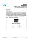
Schematic diagram
The schematic diagram of the EK3LV02DL evaluation kit is shown in Figure 25.
Figure 25. Schematic diagram for EK3LV02DL board
29/32
Bill Of Material
9
UM0285
Bill Of Material
The Bill of Material for the EK3LV02DL evaluation kit is given in Table 2.
Table 2.
Bill Of Material
Designator
Description
Comment
Footprint
C1
10u
C1206_POL
C2
4u7
C1206_POL
C3
4u7
C1206_POL
C4
Capacitor
100n
0805
C5
Capacitor
100n
0805
C6
Capacitor
100n
0805
C7
Capacitor
100n
0805
C8
Capacitor
47n
0805
C9
Capacitor
220n
0805
10u
C1206_POL
C10
Cosc1
Capacitor
33p
0805
Cosc2
Capacitor
33p
0805
D1
SMD_LED red
SMD_LED
D3
SMD_LED green
SMD_LED
D4
J1
USB_B
USB_B
J2
ICP
HEADER_5X2_A
SPI
HDR1X7
R1
180R
0805
R2
100R
0805
R3
100R
0805
R5
100R
0805
R6
1k5
0805
R7
10K
0805
R8
10K
0805
Riccsel1
10k
0805
SW1
NReset
SMT_Button
SW2
SMT_Button
SMT_Button
SW3
SMT_Button
SMT_Button
U1
LIS3LV02DL
TLGA_4.4x7.5x1_16L
U2
ST72F651AR6T1E
TQFP64_10x10
12MHz
OSC_SMD
J3
Yoscm1
30/32
SMD_LED_3C
Header, 7-Pin
Crystal
UM0285
10
Revision history
Revision history
Table 3.
Document revision history
Date
Revision
13-Sep-2006
1
Changes
Initial release.
31/32
UM0285
Please Read Carefully:
Information in this document is provided solely in connection with ST products. STMicroelectronics NV and its subsidiaries (“ST”) reserve the
right to make changes, corrections, modifications or improvements, to this document, and the products and services described herein at any
time, without notice.
All ST products are sold pursuant to ST’s terms and conditions of sale.
Purchasers are solely responsible for the choice, selection and use of the ST products and services described herein, and ST assumes no
liability whatsoever relating to the choice, selection or use of the ST products and services described herein.
No license, express or implied, by estoppel or otherwise, to any intellectual property rights is granted under this document. If any part of this
document refers to any third party products or services it shall not be deemed a license grant by ST for the use of such third party products
or services, or any intellectual property contained therein or considered as a warranty covering the use in any manner whatsoever of such
third party products or services or any intellectual property contained therein.
UNLESS OTHERWISE SET FORTH IN ST’S TERMS AND CONDITIONS OF SALE ST DISCLAIMS ANY EXPRESS OR IMPLIED
WARRANTY WITH RESPECT TO THE USE AND/OR SALE OF ST PRODUCTS INCLUDING WITHOUT LIMITATION IMPLIED
WARRANTIES OF MERCHANTABILITY, FITNESS FOR A PARTICULAR PURPOSE (AND THEIR EQUIVALENTS UNDER THE LAWS
OF ANY JURISDICTION), OR INFRINGEMENT OF ANY PATENT, COPYRIGHT OR OTHER INTELLECTUAL PROPERTY RIGHT.
UNLESS EXPRESSLY APPROVED IN WRITING BY AN AUTHORIZED ST REPRESENTATIVE, ST PRODUCTS ARE NOT
RECOMMENDED, AUTHORIZED OR WARRANTED FOR USE IN MILITARY, AIR CRAFT, SPACE, LIFE SAVING, OR LIFE SUSTAINING
APPLICATIONS, NOR IN PRODUCTS OR SYSTEMS WHERE FAILURE OR MALFUNCTION MAY RESULT IN PERSONAL INJURY,
DEATH, OR SEVERE PROPERTY OR ENVIRONMENTAL DAMAGE. ST PRODUCTS WHICH ARE NOT SPECIFIED AS "AUTOMOTIVE
GRADE" MAY ONLY BE USED IN AUTOMOTIVE APPLICATIONS AT USER’S OWN RISK.
Resale of ST products with provisions different from the statements and/or technical features set forth in this document shall immediately void
any warranty granted by ST for the ST product or service described herein and shall not create or extend in any manner whatsoever, any
liability of ST.
ST and the ST logo are trademarks or registered trademarks of ST in various countries.
Information in this document supersedes and replaces all information previously supplied.
The ST logo is a registered trademark of STMicroelectronics. All other names are the property of their respective owners.
© 2006 STMicroelectronics - All rights reserved
STMicroelectronics group of companies
Australia - Belgium - Brazil - Canada - China - Czech Republic - Finland - France - Germany - Hong Kong - India - Israel - Italy - Japan Malaysia - Malta - Morocco - Singapore - Spain - Sweden - Switzerland - United Kingdom - United States of America
www.st.com
32/32