1
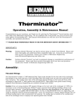
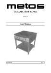
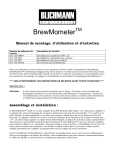
TopTier tm Modular Brewing Stand Operation, Assembly & Maintenance Manual Congratulations on your purchase, and thank you for selecting the TopTiertm brewing stand from Blichmann Engineering. We are confident that it will provide you years of service and many gallons of outstanding beer. This manual will familiarize you with the assembly, installation procedures, and use of the TopTiertm brew stand and accessories. **** PLEASE READ THOROUGHLY PRIOR TO USE FOR IMPORTANT SAFETY INFORMATION **** IMPORTANT !! Danger: Sections labeled “Danger” are critical to follow and understand to reduce risk of serious injury or death. Please read these thoroughly and understand them completely before use. If you do not understand them or have any questions, contact your retailer or Blichmann Engineering (www.BlichmannEngineering.com) before use. Do NOT at ANY time operate the product until you have thoroughly read and understood these instructions! Warning: Sections labeled “Warning” can lead to serious injury or death if not followed. Please read these thoroughly and understand them completely before use. If you do not understand them or have any questions, contact your retailer or Blichmann Engineering (www.BlichmannEngineering.com) before use. Caution: Sections labeled “Caution” can lead to equipment damage or unsatisfactory performance of the equipment. Please read these sections thoroughly. If you have any questions, contact your retailer or Blichmann Engineering (www.BlichmannEngineering.com) before use. Assembly: The TopTiertm Modular Brewing stand ships disassembled to allow it to be shipped more economically and conveniently via ground carriers. A list of components follows, and also a list of basic tools you’ll need to complete the assembly. NOTE: since the stand is modular, the burner and shelf tiers can be placed in a multitude of configurations and infinite locations on the stand. Therefore, the gas manifold piping is NOT included and must be installed and purchased locally by the user. However, we do include most of the fittings you’ll need. Parts List: The following items are shipped with each stand. Box 1 6ft aluminum mast Box 2 4 - black legs 6 - stainless steel arms (3 LH, 3 RH) 1 - Gas regulator Bag 1: 2 2 2 2 4 - wheels wheel brackets axle bolts 3/8” nuts and lock washers 5/16 X ½” long bolt and nuts Bag 2: 14 - T-slot plates (bars with 3 threaded holes) Bag 3: 42 - 5/16 X 1/2” long bolts and washers 2 - P-clips (used to affix your gas piping to the mast) 2 - 5/16 X 1-3/4” bolt with 2 hex nuts, 3 washers, 1 square nut installed 4 - Leveling feet 1 – ½” NPT pipe plug 1 – 3/8 flare X 1/2 NPT brass adapter Burner Tier (per burner ordered) 1 2 1 1 1 1 1 4 8 7 1 1 1 - Burner - Burner torsion brackets (1 LH, 1 RH) - Brass needle valve - Stainless gas flex hose (bellow type) – P-clip assembly with bolts/nuts/washers – ½” NPT pipe T – 3/8 flare X 1/2 NPT brass adapter -Stainless pot retaining bars - 6mm bolts & nuts – 1/4” X 1/2 bolts/nuts/washers - Stainless air damper - Spring - Brass gas orifice fitting Shelf Tier (per shelf ordered) 1 - Stainless shelf 2 - Stainless angle brackets 8 - Stainless #10 screws and nuts 2 Tool List: The following basic tools are required to assemble the stand and are not included with the product: 7/16”, 1/2” and 9/16” wrenches (for the legs, tier arms, wheels, and burner brackets) 10mm and 17mm (or 11/16”) wrenches (for the pot retaining bars, and installing burners on tier arms) Adjustable wrench Torque wrench for tightening the arms and legs #2 Phillips head screwdriver and 3/8” open end wrench (for optional shelf tier) Optionally, socket wrenches of the above size will speed assembly. Assembling the Stand Begin assembly by locating a flat, level hard surface to work on such as a concrete surface or hard floor. Install the t-slot plates on the legs using the 5/16” hardware. Note that the washers are installed between the head of the bolt and the inside surface of the leg. You will need to install 2 plates on each leg. Next, thread a leveling foot in each leg as shown in Fig 2. Caution: ALWAYS use the washer between the head of the bolt and the leg. Failure to use the washer will cause the bolt to penetrate too deeply into the t-slot and possibly damage the extrusion. Tip: Thread the bolt into the t-slot plate only about 1 turn – this will make it easier to install the leg on the aluminum mast where it will be positioned and tightened fully. Install each leg onto the extrusion by sliding the plates into the mating slot on the mast as shown on Fig 3. Be sure to install it 1.5” above the bottom of the mast as shown in Fig 4. Tightening the nut snugly (20 ft-lb or 27 N-m) using a torque wrench. Caution: Excessive tightening may permanently deform the mast. Fig. 1 Fig. 2 Washer This Side v 3 Fig. 3 Fig. 4 When you have finished installing a leg on all 4 sides of the mast, place it upright on the floor. Using a carpenter’s level as shown in Fig 5, level the product on all sides using the adjustable leveling feet. Ensure that each leveling foot is touching the hard floor so it does not rock. The assembly of the base stand is now complete! Fig. 5 Fig. 6 Must rest on floor! Danger!: ALWAYS ensure that the mast rests firmly on the hard surface as shown in Fig 6! This allows the weight from the pots to be borne by the mast instead of the legs. Failure to have the mast resting on the floor will add excessive load to the legs possible leading to failure and severe personal injury from burns and falling objects!! Assembling the Burner Tiers Each burner is shipped with all legs assembled. To mount it onto the mast, the arms (1LH, 1RH) and the torsion brackets (1RH, 1LH) must be assembled prior to installing them on the mast of the stand. Begin by installing the torsion brackets to one of the legs on the burner frame as shown in Fig 7. Tip: Leave all fasteners finger tight at first which will ease assembly onto the mating parts. You can tighten all the fasteners once you have the burner tier fully assembled. 4 Tip: Plan out the position of the tiers ahead of assembly and make sure to install the torsion brackets on the leg that will face the mast. It is helpful to have the inlet to the burner (the venturi) facing the side of the operator. Fig 8 shows a top view of an installed burner tier to help visualize how the parts fit together. Orient so inlet faces operator when installed Fig. 7 Fig. 8 Note – burner is inverted to show fasteners After installing the burner torsion brackets, remove the 2 legs where the arms will go – ref Fig 9. The arms (1 LH, 1 RH) will be “sandwiched” between the legs and the wind screen (ring) on the burner. Pay close attention to the orientation of the arms on the burners. Fig 10 shows how the arm is placed between the leg and the burner wind ring. Fig 11 shows a side view of the burner assembly to show the orientation of the arm on the burner assembly. Referring to Fig 12, install a t-slot plate on the inside of each arm as was done for installing the legs. Again, only thread the bolts in about 1 turn to make installing the tier onto the mast easier. Caution: ALWAYS use the washer between the head of the bolt and the tier arm. Failure to use the washer will cause the bolt to penetrate too deeply into the t-slot and possibly damage the mast extrusion. Tip: We have applied a nickel based antiseize to the threads to aid in disassembly after extended periods of high temperature use. If you are installing new burners that have never been used, you will not need to reapply more antiseize. If you are installing a burner that you purchased previously that has been used, we recommend that you apply a nickel based antiseize compound (made for stainless steel) to aid any future disassembly. This compound can be purchased through McMaster.com ref item number 10295K29. Fig. 10 Fig. 9 Remove these 2 legs 5 Fig. 11 Fig. 12 Lastly, install the 4 pot retaining bars as shown in Fig 13 using the 6mm nuts and bolts provided with the bars. Note that the bars can be moved in/out to accommodate pots up to 20” in diameter. Fig 13a shows the hole positions to use for different diameter pots. At this time tighten all of the hardware on the burner tier. This concludes the assembly of the burner tiers. Fig. 13 Fig. 13a Assembling the Shelf Tiers Using the hardware provided with the shelf tier install the angle brackets onto the bottom side of the shelf as shown in fig 14. Note that the heads of the screws should be on the top of the shelf so they do not interfere with coolers placed on the shelf. Next, install the arms on the INSIDE of the angle brackets as shown in Fig 15. Also shown in Fig 15, install 2 t-slot plates on the inside of each arm as was done for installing the legs previously. It is recommended to leave the fasteners only finger tight until the tier is installed on the stand to aid leveling of the shelf tier. 6 Fig. 14 Fig. 15 Caution: ALWAYS use the washer between the head of the bolt and the tier arm. Failure to use the washer will cause the bolt to penetrate too deeply into the t-slot and possibly damage the mast extrusion. Installing the Tiers Installation of the tiers is done by inserting the t-slot plates into the t-slots of the mast as shown in Fig 16. It is helpful to have someone assist you in installing them. Position the tier in the desired location and tighten the t-slot plate bolts slightly so they can be adjusted as needed in the leveling step that follows. Tip: The tiers can be installed on all 4 sides of the mast! As shown in Fig 17, use a carpenter’s level and level the burner front to back and side to side. Tightening the nuts snugly (20 ft-lb or 27 N-m) using a torque wrench. Caution: Excessive tightening may permanently deform the mast. Fig. 16 Fig. 17 Shelf tiers are installed identically to the burner tiers. AT THIS TIME FULLY TIGHTEN ALL FASTENERS. 7 Installing the Fuel Manifold Since the TopTier brewing stand is so modular, the fuel manifold piping is NOT included with the product because we cannot determine in advance which positions you’ll locate your tiers and how many tiers will be fired. However, we include most of the fittings you will need to complete the manifold. All the necessary pipe and any additional fittings can be readily purchased locally at any hardware store or home improvement store. All the hardware we provide is ½” NPT which is very common. In most installations, all you’ll need to provide is straight lengths of pipe (pipe nipples). If you can’t find the exact length you need you can piece shorter nipples together wuth pipe couplings. Or most hardware stores can cut the pipe to the exact length you need. Install the orifice, spring, damper and needle valve onto the burner venturi as shown in Fig 18 and 19. The spring goes on the brass fitting between the damper and the fitting. Fig. 18 Fig. 19 Connect the stainless steel flexible metal bellows tube to the needle valve and secure to the burner with the pclip as shown in Fig 20. IMPORTANT: when installing the stainless bellow gas hose take care to ensure that the hose is square to the fitting (on both ends) while tightening the nut. Failure to do this may result in a gas leak. ALWAYS CHECK HOSES FOR LEAKS PRIOR TO EACH USE! Fig. 20 8 The purpose of the fuel manifold is to distribute propane fuel from the supplied single regulator to the individual burners. To accomplish this, a series of elbows and “T’s” are needed to split the flow into 2 or 3 paths depending on the quantity of burners purchased. A T and brass flare X NPT adapter are provided with each burner. If you are only using one burner, simply connect the regulator hose directly onto the needle valve; a manifold is not necessary in that case. In addition, an additional brass adapter is provided with the stand to connect the regulator to the manifold. A pipe plug is provided with the stand to cap off the top of the manifold on the branch of the T that isn’t used at the top of the manifold. You will need to use Teflon pipe tape or pipe dope (not included) at each joint to get a gas tight seal. Do NOT use pipe tape/dope on the flare connections. Just the NPT thread connections. Caution: Since local gas piping codes vary from State to State, we recommend that you contact your local authorities for advice, or hire a professional plumber for assembling and installing the fuel manifold. A typical manifold assembly is shown close-up in Fig 21 and shown installed on the stand in Fig 22. Use this as a reference for designing your manifold based on your specific configuration. TIP: Orient the burner venturi’s (the end with the damper) to face you when you operate the stand, and locate the manifold on the side facing you. This makes it easier to adjust the burner output and ignite the burners. If you have located a tier 90 deg from another tier, there are a few additional pipe fittings you will need to purchase so that the flex hose reaches to the manifold. That is shown at the end of this section. TIP: Depending on how you configure your stand, the hardware for mounting the p-clips (used to mount the manifold pipe) may share the same t-slot as the burner t-slot plates. So be sure to install the mounting hardware in the proper sequence. Included with the stand are 2 p-clip assemblies that may be used to secure 1/2” black iron pipe to the mast via the t-slots. Fig 23 shows a close-up of the p-clips used to mount the manifold to the mast. Note that the square nuts slide into the t-slots of the mast. For easier assembly, the manifold may be installed on the mast after assembly, but you’ll want to make sure that the p-clips are in place on the mast first. Fig 24 illustrates the installation of the fuel manifold onto the mast. Fig. 21 Fig. 22 Pipes NOT included Center manifold on center post P-clip assembly 9 Orient venturi to front Figs 25, 26, and 27 show close-up views of a middle tier gas connection, upper tier connection with plug, and the regulator connection to the manifold respectively. Fig 28 shows how to route piping to reach the flex hose if your manifold is on the opposite side of your burner tier. You will need to purchase (2) 2” nipples, (1) 90 deg elbow, and a pipe coupling to complete this piping. These parts are not included with the product, but are readily available at any hardware store or home improvement center. Thread square nut flush with bottom of bolt Fig. 23 Fig. 24 P-clip assembly Tighten this nut after installing on mast Fig. 25 Fig. 26 Close-up of typical tier connection. Use plug to cap off the upper tier Fig. 27 Fig. 28 10 This concludes assembly of the TopTier brew stand. Note that you can easily reconfigure your stand at any time, or partially disassemble for transport or storage!! Operation: This section of the manual discusses proper operational techniques for safety and successful operation. Danger! It is vital for the safety of yourself, others, and personal property that you thoroughly read and understand and follow the important safety instructions in this manual. If at any time you do not understand how to assemble, operate, locate, or install this equipment or have any questions about this manual do not operate the equipment. Contact your Retailer or Blichmann Engineering for assistance. ***** By purchasing and operating this equipment you agree and understand that brewing beer has inherent dangers and risks that include, but are not limited to burns, scalds, fire, falling objects and property damage and you agree that Blichmann Engineering, LLC is not liable in any way for consequences arising from you personally accepting these risks. If at any time you are not completely willing to accept personal responsibility for these risks DO NOT USE THE EQUIPMENT. In no situation should this equipment EVER be used indoors! Do not use this equipment while drinking alcohol or while under the influence of alcohol or other drugs. This product, like any gas appliance, can be extremely dangerous and can cause burns, scalds or start a fire. Misuse of outdoor cooking equipment can result in personal injury and property damage. This product generates carbon monoxide gas. NEVER operate this product indoors or in any confined area where there is not adequate ventilation. All surfaces of this product may become extremely hot during use. Never Do These Things! NEVER LEAVE THIS EQUIPMENT UNATTENDED NEVER EXCEED 250LB (115KG) PER BURNER, OR 125 LB (57KG) PER SHELF NEVER HEAT COOKING OIL WITH THIS EQUIPMENT NEVER ALLOW CHILDREN NEAR THIS EQUIPMENT DURING USE NEVER operate on soft, combustible or uneven surfaces like dirt, gravel, wood or asphalt NEVER operate indoors, in a garage, under an overhang, porch, deck, carport or similar structure NEVER use near and combustible chemicals, gasoline or other flammable vapors or liquids NEVER allow the flame to roll past the bottom of the pot NEVER install casters (wheels) to this product. NEVER operate without pot retaining bars in place NEVER lift or move a full pot of water onto or off of the stand NEVER use the regulator or needle valves as the shutoff. Use the propane tank valve! NEVER store propane tanks indoors. 11 Always Do These Things! ALWAYS OPERATE OUTSIDE ONLY, AT LEAST 30FT FROM OTHER STRUCTURES ALWAYS USE ONLY ON LEVEL AND STABLE CONCRETE, BRICK OR SIMILAR HARD NON-FLAMMABLE SURFACES. ALWAYS Keep the gas supply hose away from heated surfaces AT ALL TIMES ALWAYS Check that all fasteners are properly tightened prior to each use ALWAYS Ensure that the base of the mast (aluminum post) is resting on the hard surface ALWAYS Level the stand using the leveling feet and a bubble level prior to each use ALWAYS Check for gas leaks before each use using soapy water ALWAYS Wear protective gloves, clothing, and boots to prevent burns and scalds ALWAYS Have a fire extinguisher nearby at all times ALWAYS Use a pump or gravity to move hot liquids from or into a pot or cooler ALWAYS Use only Blichmann Engineering burners, shelves, and accessories on this stand ALWAYS Let equipment cool completely after use before moving Tier Location While the burner and shelf tiers can physically be located on any of the 4 faces of the mast and at any height it is imperative to keep the center of gravity as low as possible for safe stable operation. It is also imperative to have the weight of the pots as evenly balanced on all sides of the stand as possible. DO NOT place all tiers on one side or quadrant of the stand! Yes! Yes! Yes! NO! NO! Burner Operation Always use a long match or igniter to light the burners. Never light the burner at the venturi. Two ignition/flame inspection holes (Fig 29) have been provided for this purpose. Prior to igniting the burners, turn the needle valve fully clockwise to the OFF position and turn the air damper so that it is open about half way as shown in Fig 30. A variable pressure regulator (0-10 PSI) has been provided with the stand – ref Fig 31. Danger: Never use a different regulator with this product as serious damage can occur to the structure from excessive heat! Structural failure can cause serious personal injury or death. 12 Turn the regulator fully counterclockwise to the off position. Only then turn the valve on at the tank to the on position. Turn the regulator fully clockwise and then turn the brass needle valve counterclockwise slightly until you hear gas flowing. Immediately ignite the gas through the burner ignition hole. Fine tuning the flame: once the flame has ignited, you will adjust the needle valve and air damper (Fig 30) to reach the desired heat setting and air/fuel mixture. Looking through the flame inspection hole at the flame and turn the air damper until the flame is slightly yellow. Then slowly turn it back until the flame turns pale blue and is still touching the nozzles in the burner casting. If the flame lifts off of the nozzles, or you hear a low grumbling from the flame it is getting too much air through the damper and you will need to close it slightly. If it is yellow, there is not adequate air and you will need to increase the air flow. As you increase the gas flow via the needle valve, it may be necessary to readjust the air damper. Note that optimum heating speed and efficiency can only be achieved with a properly adjusted flame. Ignition / inspection holes Fig. 29 Fig. 30 Fig. 31 Tip: In cold weather, or in cases where more than one burner is running simultaneously, the propane tank may begin to freeze up and not flow enough gas to the burners. If this occurs, place the propane tank in a tank of luke warm water about half way up the tank. This will keep the propane warm and keep it flowing properly. 13 Maintenance The TopTiertm brew stand requires little maintenance. Inspect fasteners and hoses regularly and replace as needed. After brewing and allowing the equipment to cool, wipe any drips off with ordinary soap and a soft sponge and allow to dry. Warranty The TopTiertm burner is warranted to be free of defects in materials and workmanship for a period of 1yr from the date of purchase (proof of purchase required). Specifically EXCLUDED from this warranty are normal wear and tear, damage from abuse, misuse, failure to follow cleaning and maintenance procedures, and damage from over tightening fasteners. Blichmann Engineering is not responsible for incidental or consequential damages arising from use or misuse of this product. This product is intended for OUTDOOR home use only. No warranty or guarantee of suitability (express or implied) is given for commercial use or indoor use of this product. Blichmann Engineering must be notified within 7 days of the delivery date of any hidden shipping damage. Customer is responsible for shipping damage outside of this time period. Customer is responsible to keep all original packing material for warranty returns – Blichmann Engineering, LLC is not responsible for damage from improperly packaged warrantee returns and these repair costs will be the responsibility of the customer. Resolution of warranty claims will be by repair or replacement and will be the decision solely of Blichmann Engineering. Shipping costs for warrantee returns are covered only for the contiguous United States. User is responsible for packaging costs and shipping damage if not returned in original packing. Approval for return must be provided by Blichmann Engineering prior to any return. 14 TopTiertm Brewing Stand Owner’s Manual – V5 Blichmann Engineering, LLC 2012 15