1
RK P01M
CLIMATE REGULATOR
FOR HEATING SYSTEMS
USER MANUAL
Read carefully before use
───────────────────────────
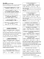
CONTENTS OF THE PACKAGE
────────────────────────────
───────────────────────────
OPTIONAL COMPONENTS
────────────────────────────
CLIMATE CONTROL UNIT (1 piece)
Code RK P01M
ROOM TEMPERATURE PROBE
Code ST AD01
EXTERNAL TEMPERATURE PROBE (1 piece)
Code ST ED01
REMOTE CONTROL
Code ACC RK3 COM
SUPPLY/RETURN TEMPERATURE PROBE (2 pcs)
Code ST CD02
RELAY MODULE TO CONVERT LIVE CONTACTS TO
VOLTAGE FREE CONTACTS
Code ACC REL 02
3/36
RKP01M0001SE 024351 111214
───────────────────────────
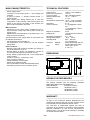
MAIN CHARACTERISTICS
────────────────────────────
──────────────────────────
TECHNICAL FEATURES
───────────────────────────
- Power supply 230V~
- 4 outputs (3 on/off under power + 1 with voltage free
contacts)
- 6 inputs (4 probes + 1 ambient remote control + 1
remote switch)
- Wide backlit LCD display allows you to view the
configuration of the hydraulic chart of the system, the
status of the outputs, the status of the sensors and
other various information and data.
Power supply:
Maximum consumption:
Type of sensors:
Sensor operation limit:
Accuracy:
Temperature reading field:
Resolution:
Contact capacity:
Main functions:
- Adjustment of the supply water temperature with 3way motorized mixing valve with 3-point control and
supply pump
- Adjustment of the temperature of the boiler with 1 or 2
stage control of the burner
Degree of protection:
Backlight off:
Operating temperature:
Storage temperature:
Humidity limits:
The temperature of the supply water or of the boiler can
be adjusted according to:
- the temperature of the outside air
- the temperature of the outside air and the ambient
temperature
Container:
Size:
Other functions:
- Remote control with ambient controller (to change to
the set temperature by ±5°C)
- Remote switch (to which it is possible to connect an
on/off switch that replaces the internal chrono)
- Hourly weekly programming with 4 room temperature
control modes:
Comfort - Economy - Anti-freeze - OFF
- Up to 4 types of systems
- Freeze protection of the system
- Offset on the external probes
- Anti-condensation function with dedicated pump
- Anti-blocking function of the circulation pump
Material:
Colour:
±230V~ ±10% 50/60Hz
<1,5 VA
NTC 10K @25°C B3977
-20 °C .. +120 °C
± 1.0°C
-20°C .. +120°C (probes)
±5°C (remote controller)
0.1°C
3 x 2(1)A@250V~ SPST
live
1 x 2(1)A@250V~ SPDT
voltage free
IP 40
~20 seconds from last key
pressed
0°C .. 40°C
-10°C .. +50°C
20% .. 80% RH
(non condensing)
Self-extinguishing ABS V0
Signal white (RAL 9003)
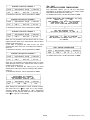
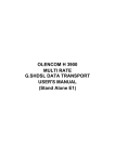
156 x 108 x 47 mm
(L x A x P)
108mm
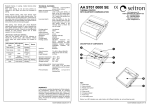
────────────────────────────
DIMENSIONS
────────────────────────────
156mm
46.5mm
A
────────────────────────────
NORMATIVE REFERENCES
────────────────────────────
The product complies with the following standards
(EMC 2004/108/c and LVD 2006/95/c):
EMC Standards:
EN 55014-2 (1997)
Product standard:
EN 60730-1 (2011)
EN 60730-2-7 (1991)
EN 60730-2-9 (1995)
────────────────────────────
WARRANTY
────────────────────────────
As part of our continuous product development, the
manufacturer reserves the right to make changes to the
technical data and specifications without notice.
The consumer is guaranteed against any lack of
conformity of the product in accordance with European
Directive 1999/44/c as well as the manufacturer’s
warranty policy. The full text of the warranty is available
on request from the seller.
4/36
RKP01M0001SE 024351 111214
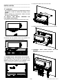
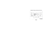
4. Secure the base of the unit to the wall.
───────────────────────────
INSTALLATION
───────────────────────────
a WARNING
- The installer must abide by all applicable technical
standards in order to ensure the safety of the
system.
- Before making any connections, make sure that
the mains is disconnected.
TO INSTALL THE DEVICE,
FOLLOWING OPERATIONS:
PERFORM
130m
m
THE
1. Remove the screw indicated and remove the cover.
5. Replace the cover with the electronics at the bottom.
2. Remove the two screws shown and separate the
cover with the electronics from the bottom.
6. ASSEMBLY WITH CABLE ENTRY ON
BOTTOM:
Insert the cable ties and/or dowels supplied.
THE
3. ASSEMBLY WITH CABLE ENTRY ON THE BACK:
If the installation does not require the use of cable ties
(supplied), remove, with the help of a screwdriver, the
dowels at the base needed for the passage of the
cables, and at step 6 insert the dowels supplied.
5/36
RKP01M0001SE 024351 111214
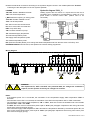
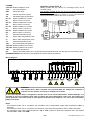
8. Make the electrical connections according to the hydraulic diagram chosen in the installer parameter "P1 SCH".
Following are the descriptions of the four systems possible.
LEGEND:
TAF OFF: Enable / Disable anti-freeze
TAF: Anti-freeze temperature
I_MAX: Maximum opening or closing pulse
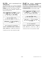
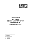
Hydraulic diagram 'SCH_1':
Heating system with the control of a 3-point servo motor and a
circulation pump. Possibility of compensation by means of a "Ta"
probe and/or a remote control "RC" (neither have to be
connected).
TCO OFF: Enable / Disable Cut-Off
TCO: Cut-Off temperature
ton: Servo motor ON command time
tof: Servo motor OFF command time
DEL: Pump OFF delay
TAL: Periodic activation of pump
TD: Calculated supply temperature
Te: External temperature probe
Td: Supply water temperature probe
Ta: Ambient temperature probe
RC: (Remote Controller) allows you to change the ambient temperature set from the user menu U4>TCR by ±5°C
EXTERNAL SWITCH: On/off switch, that replaces the internal weekly programmer
Wiring diagram
WARNING
The outputs OUT 1, OUT 2 and OUT 3 are powered 230V; if a voltage free command is
required, use the specific accessory for voltage free contacts.
Notes:
- If the ambient probe "TA" is connected, the calculation of the compensated supply water temperature "TDC" is
automatic.
- If the Remote Control "RC" is connected, the calculation of the Set-Point temperature "TC" or "TR" is automatic.
- The calculation of the supply water temperature, "TD" or "TDC", takes into account the limitations set in the installer
parameter P2 in "TDL" and "TDM".
- Unit OFF: the servo motor is closed with a pulse equal to "Imax" (see paragraph "Adjustment with mixing valve with
3-point servo motor and supply pump").
- If the measured supply water temperature "Td" is less than the temperature detected by the external probe "Te", the
servo motor will be closed with a pulse equal to "Imax" (see paragraph "Adjustment with mixing valve with 3-point
servo motor and supply pump").
6/36
RKP01M0001SE 024351 111214
LEGEND:
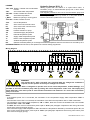
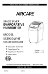
Hydraulic diagram 'SCH_2':
Heating system with the control of a 3-point servo motor, a
TAC OFF: Enable / Disable anti-condensation
circulation pump, an anticondensate pump and a return water
function
temperature probe.
TAC:
Anti-condensation temperature
This diagram provides for the use of the recirculation pump and
TAF OFF: Enable / Disable anti-freeze
the return probe -.Tr.
TAF:
Anti-freeze temperature
Possibility of compensation by means of a "Ta" probe and/or a
remote control "RC" (neither have to be connected).
I_MAX:
Maximum opening or closing pulse
TCO OFF: Enable / Disable Cut-Off
TCO:
Cut-Off temperature
ton:
Servo motor ON command time
tof:
Servo motor OFF command time
DEL:
Pump OFF delay
TAL:
Periodic activation of pump
TD:
Calculated supply temperature
Te:
External temperature probe
Td:
Supply water temperature probe
Tr:
Return water temperature probe
Ta:
Ambient temperature probe
RC:
(Remote Controller) allows you to change the ambient temperature set from the user menu U4>TCR by ±5°C
EXTERNAL SWITCH: On/off switch, that replaces the internal weekly programmer
Wiring diagram
WARNING
The outputs OUT 1, OUT 2 and OUT 3 are powered 230V; if a voltage free command is
required, use the specific accessory for voltage free contacts.
In the event that the boiler is designed to operate even at low return temperatures, without damage, it is
possible to turn the circulation pump OFF by setting the return temperature under 10°C. The display will
show "OFF-TAC". The return probe Tr must still be connected to the terminals "Tr" even if the recirculation
pump is not used.
Notes:
- If the ambient probe "TA" is connected, the calculation of the compensated supply water temperature "TDC" is
automatic.
- If the Remote Control "RC" is connected, the calculation of the Set-Point temperature "TC" or "TR" is automatic.
- The calculation of the supply water temperature, "TD" or "TDC", takes into account the limitations set in the installer
parameter P2 in "TDL" and "TDM".
- Unit OFF: the servo motor is closed with a pulse equal to "Imax" (see paragraph "Adjustment with mixing valve with
3-point servo motor and supply pump").
- If the measured supply water temperature "Td" is less than the temperature detected by the external probe "Te", the
servo motor will be closed with a pulse equal to "Imax" (see paragraph "Adjustment with mixing valve with 3-point
servo motor and supply pump").
7/36
RKP01M0001SE 024351 111214
LEGEND:
TAC OFF: Enable / Disable TAC function
TAC:
Anti-condensation temperature
TAF OFF: Enable / Disable TAF function
TAF:
Anti-freeze temperature
TCO OFF: Enable / Disable Cut-Off
TCO:
Cut-Off temperature
DEL:
Pump OFF delay
TAL:
Periodic activation of pump
TD:
Calculated supply temperature
tb1 off:
Enable / Disable tb1 function
tb1:
Burner 1 ON on minimum
to1 off:
Enable / Disable to1 function
to1:
Burner 1 OFF on minimum
Te:
External temperature probe
Td:
Supply water temperature probe
Tr:
Return water temperature probe
Ta:
Ambient temperature probe
Hydraulic diagram 'SCH_3':
Heating system with the 2-point control (ON/OFF) of a single
stage burner and a circulation pump.
This diagram provides for the use of the recirculation pump and
the return probe -.Tr.
Possibility of compensation by means of a "Ta" probe and/or a
remote control "RC" (neither have to be connected).
RC:
(Remote Controller) allows you to change the ambient temperature set from the user menu U4>TCR by ±5°C
EXTERNAL SWITCH: On/off switch, that replaces the internal weekly programmer
Wiring diagram
WARNING
The outputs OUT 1, OUT 2 and OUT 3 are powered 230V; if a voltage free command is
required, use the specific accessory for voltage free contacts.
In the event that the boiler is designed to operate even at low return temperatures, without damage, it is
possible to turn the circulation pump OFF by setting the return temperature under 10°C. The display will
show "OFF-TAC". The return probe Tr must still be connected to the terminals "Tr" even if the recirculation
pump is not used.
Notes:
- If the ambient probe "TA" is connected, the calculation of the compensated supply water temperature "TDC" is
automatic.
- If the Remote Control "RC" is connected, the calculation of the Set-Point temperature "TC" or "TR" is automatic.
- The calculation of the supply water temperature, "TD" or "TDC", takes into account the limitations set in the installer
parameter P2 in "TDL" and "TDM".
8/36
RKP01M0001SE 024351 111214
LEGEND:
TCO OFF: Enable / Disable Cut-Off
TCO:
Cut-Off temperature
DEL:
Pump OFF delay
TAL:
Periodic activation of pump
TD:
Calculated supply temperature
tb1 off: Enable / Disable tb1 function
tb1:
Burner 1 ON on minimum
tb2 off:
tb2:
to1 off:
to1:
to2 off:
to2:
Te:
Td:
Hydraulic system 'SCH_4':
Heating system with the control of a two-stage burner and a
circulation pump.
This diagram provides for the use of the recirculation pump and
the return probe -.Tr.
Possibility of compensation by means of a "Ta" probe and/or a
remote control "RC" (neither have to be connected).
Enable / Disable tb2 function
Burner 2 ON on minimum
Enable / Disable to1 function
Burner 1 OFF on minimum
Enable / Disable to2 function
Burner 2 OFF on minimum
External temperature probe
Supply water temperature probe
Tr:
Return water temperature probe
Ta:
Ambient temperature probe
TAC:
Anti-condensation temperature
TAC OFF: Enable / Disable TAC function
TAF OFF: Enable / Disable TAF function
TAF:
Anti-freeze temperature
RC:
(Remote Controller) allows you to change the ambient temperature set from the user menu U4>TCR by ±5°C
EXTERNAL SWITCH: On/off switch, that replaces the internal weekly programmer
Wiring diagram
WARNING
The outputs OUT 1, OUT 2 and OUT 3 are powered 230V; if a voltage free command is
required, use the specific accessory for voltage free contacts.
In the event that the boiler is designed to operate even at low return temperatures, without damage, it is
possible to turn the circulation pump OFF by setting the return temperature under 10°C. The display will
show "OFF-TAC". The return probe Tr must still be connected to the terminals "Tr" even if the recirculation
pump is not used.
Notes:
- If the ambient probe "TA" is connected, the calculation of the compensated supply water temperature "TDC" is
automatic.
- If the Remote Control "RC" is connected, the calculation of the Set-Point temperature "TC" or "TR" is automatic.
- The calculation of the supply water temperature, "TD" or "TDC", takes into account the limitations set in the installer
parameter P2 in "TDL" and "TDM".
9/36
RKP01M0001SE 024351 111214
OPERATING LOGIC
Operating logic in accordance with the hydraulic diagram 'SCH_1' (see page 6):
Unit ON
Unit OFF
Operating logic in accordance with the hydraulic diagram 'SCH_2' (see page 7):
Unit ON
Unit OFF
10/36
RKP01M0001SE 024351 111214
Operating logic in accordance with the hydraulic diagram 'SCH_3' (see page 8):
Unit ON
Unit OFF
Operating logic in accordance with the hydraulic diagram 'SCH_4' (see page 9):
Unit ON
Unit OFF
11/36
RKP01M0001SE 024351 111214
NOTES FOR THE ELECTRICAL CONNECTIONS
The following page shows the resistance values of
the probes.
a WARNING
- For the correct adjustment of the ambient and
external temperature, it is recommended to
install the probes away from sources of heat, air
currents or particularly cold walls (thermal
bridges).
- To connect the probes use cables with a
minimum cross-section of 1.5 mm² and a
maximum length of 25 m. Do not pass the probe
cables through the mains conduits.
- Connect the device to the mains supply by
means of a bipolar switch complying with the
regulations in force and with a contact opening
distance of at least 3 mm in each pole.
- Il the load driven by the relay of the chronothermostat works at the mains voltage, it is
necessary that the connection is made by means
of an omnipolar switch complying with the
regulations in force and with a contact opening
distance of at least 3 mm in each pole..
- The installation and electrical connection of the
device must be carried out by trained personnel
and in compliance with applicable laws.
- Before making any connections, make sure that
the mains power is disconnected.
EXTERNAL CONTROLS:
It is possible to connect two devices to the climate
regulator, which will affect the adjustment of the ambient
temperature:
RC (remote control): input for the connection of a
remote control which allows you to change the comfort
"TC" or economy "TR" temperature set by ±5°C
(accessory purchased separately).
REMOTE CONTACT: input for the connection of an
ON/OFF contact (for example a switch or a timer), which
will replace the function of the internal
chrono-thermostat (accessory purchased separately).
9. Close the unit by replacing the cover.
POWER SOURCE
It is advisable to add to a fuse to the power supply line,
of a capacity suitable for the loads connected, which
intervenes in the event of a short circuit.
The maximum capacity of the fuse cannot be greater
than 10A 250V~.
EARTH TERMINAL
On the base of the unit is a brass terminal board to
connect the protective earth conductors of the various
devices connected to the unit.
LOADS
PUMP (C-NO-NC): Circulation pump output with
voltage free changeover contacts
(SPDT).
OUT 1 (L1-N):
ON/OFF output (powered).
OUT 2 (L2-N):
ON/OFF output (powered).
OUT 3 (L3-N):
ON/OFF output (powered).
a
WARNING
When closing the unit make sure that the
extractable terminal boards have been inserted
correctly (the screws of the terminal board must be
facing upwards).
PROBES
The climate regulator accepts the following type of
temperature probes: NTC 10KΩ @ 25°C ±1%.
Te (External temperature probe): probe, fixed to the
wall, to be placed outside (probe supplied).
Td (Supply water temperature probe): probe, fixed to
a pipe, to be placed on the supply water piping (probe
supplied).
Tr (Return water temperature probe): probe, fixed to a
pipe or well, to be placed on the return water piping
(probe purchased separately).
Ta (Ambient temperature probe): probe, fixed to the
wall, to be placed inside the room where the
temperature is to be adjusted
(probe purchased
separately).
12/36
RKP01M0001SE 024351 111214
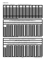
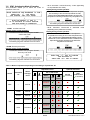
PROBE TABLE
Resistance @ 25℃ : 10,00㏀ ±1,0%
B Constant: 3977K (25℃/85℃) ±1,0%
Temp℃ Ravg ㏀ Temp℃ Ravg ㏀ Temp℃ Ravg ㏀ Temp℃ Ravg ㏀ Temp℃ Ravg ㏀ Temp℃ Ravg ㏀
-20
-18
-16
-14
-12
-10
-8
-6
-4
-2
0
96,26
85,88
76,72
68,64
61,48
55,15
49,53
44,54
40,10
36,15
32,63
2
4
6
8
10
12
14
16
18
20
22
29,49
26,68
24,17
21,92
19,91
18,10
16,47
15,00
13,69
12,50
11,42
24
26
28
30
32
34
36
38
40
42
44
10,45
9,572
8,776
8,054
7,339
6,804
6,263
5,770
5,3212
4,9117
4,5378
46
48
50
52
54
56
58
60
62
64
66
4,1961
3,8835
3,5973
3,3351
3,0946
2,8738
2,6710
2,4844
2,3128
2,1546
2,0089
68
70
72
74
76
78
80
82
84
86
88
1,8744
1,7502
1,6355
1,5294
1,4312
1,3402
1,2560
1,1778
1,1052
1,0378
0,9751
90
92
94
96
98
100
0,9169
0,8626
0,8121
0,7650
0,7211
0,6801
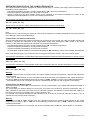
COMPENSATION COEFFICIENT KS TABLE
Tc = Comfort Temperature (set in the parameter) = 20°C,
KS = External Compensation Coefficient, Te = External Temperature
TD = Tc + [KS x (Tc - Te)]
Supply temperature calculated on the basis of the compensation with the External temperature Te
Te
-30
-20
-10
0
10
20
30
40
KS
0,5
TD
45
40
35
30
25
20
15
10
KS
1
TD
70
60
50
40
30
20
10
0
KS
1,5
TD
95
80
65
50
35
20
-5
-10
KS
2
TD
120
100
80
60
40
20
0
-20
KS
2,5
TD
145
120
95
70
45
20
-5
-30
KS
3
TD
170
140
110
80
50
20
-10
-40
KS
3,5
TD
195
160
125
90
55
20
-15
-50
KS
4
TD
220
180
140
100
60
20
-20
-60
KS
4,5
TD
245
200
155
110
65
20
-25
-70
KS
5
TD
270
220
170
120
70
20
-30
-80
COMPENSATION COEFFICIENT KA TABLE
Tc = Comfort Temperature = 20°C (set in the parameter),
KA = Ambient Compensation Coefficient, Ta = Ambient Temperature
TDC = TD + Dta = TD + [KA x (Tc-Ta)]
Supply temperature calculated on the basis of the compensation with the temperatures Te and Ta
dTDA = [KA x (Tc-Ta)]
Value that is added to TD which is compensated also via the ambient probe Ta
Te
-30
-20
-10
0
10
20
30
40
KA
0,5
dTDA
25
20
15
10
5
0
-5
-10
KA
1
dTDA
50
40
30
20
10
0
-10
-20
KA
1,5
dTDA
75
60
45
30
15
0
-15
-30
KA
2
dTDA
100
80
60
40
20
0
-20
-40
KA
2,5
dTDA
125
100
75
50
25
0
-25
-50
13/36
KA
3
dTDA
150
120
90
60
30
0
-30
-60
KA
3,5
dTDA
175
140
105
70
35
0
-35
-70
KA
4
dTDA
200
160
120
80
40
0
-40
-80
KA
4,5
dTDA
225
180
135
90
45
0
-45
-90
KA
5
dTDA
250
200
150
100
50
0
-50
-100
RKP01M0001SE 024351 111214
OPERATING PRINCIPLES OF THE CLIMATE REGULATOR
The climate regulator controls and adjusts the ambient temperature by controlling the supply water temperature, TD,
depending on three parameters:
- Theoretical temperature set (TC = Comfort Temperature or TR = Economy Temperature)
- External temperature (detected by the "Te" probe connected)
- Speed of response of the entire system based on the variations of the external temperature, by means of the
adjustment factor KS settable by means of the installer parameter P2.
The formula to calculate the supply water temperature in comfort mode is the following:
TD = TC + [KS x (TC - Te)]
The formula to calculate the supply water temperature in economy mode is the following:
TD = TR + [KS x (TR - Te)]
Note:
Climate control is influenced by the presence of the probe that detects the ambient temperature and/or the presence
of the Remote Control, as described below.
Compensation with ambient temperature
When a probe that detects the ambient temperature is connected to the unit ("Ta" icon ON), the climate regulator will
be able to calculate the adjustment of the compensated supply water temperature, TDC, based on the actual
tendency of the ambient temperature as a function of the following parameters:
- Theoretical temperature set (TC = Comfort Temperature or TR = Economy Temperature)
- External temperature, detected by the "Te" probe connected
- Ambient temperature, detected by the "Ta" probe connected
- Compensation coefficient relative to the ambient temperature "KA" settable by means of the installer parameter P2.
Note: If the ambient probe is not connected, when scrolling the parameters P2 DAT, "KA" will no longer appear.
The formula to calculate the compensated supply water temperature with the ambient temperature in comfort mode is
the following:
TDC = TD + [KA x (TC - Ta)]
The formula to calculate the compensated supply water temperature with the ambient temperature in economy mode
is the following:
TDC = TD + [KA x (TR - Ta)]
Warning:
- Place the ambient probe in the place where you want to adjust the ambient temperature, otherwise the adjustment
will be distorted.
- If the value of TDC resulting from the calculation exceeds the maximum value allowed for the supply temperature,
the value of TDC will be automatically limited to the value of "TDM", settable by means of the installer parameter P2.
- If the ambient probe is not connected, the function is disabled and the "Ta" icon will not appear on the display.
Compensation with Remote Control
When the Remote Controller "RC" is connected to the unit, the compensation of the supply water temperature "TD" or
"TDC" is enabled.
The compensation is obtained taking into account the new value of the Comfort or Economy temperature, "TC" or
"TR", calculated on the basis of the value set on the Remote controller. The Remote Controller allows the variation of
the Comfort or Economy temperature set in a range between ± 5°C.
For example, if the Comfort temperature "TC" has been set to 20°C and on the Remote Controller a value of +2°C is
selected, the new Comfort value will be 22°C.
Warning:
- If the value of "TD" or "TDC" resulting from the calculation exceeds the maximum value allowed for the supply
temperature, the value of "TD" or "TDC" will be automatically limited to the value of "TDM", settable by means of the
installer parameter P2.
- If the Remote Controller is not connected, the function is disabled and the "RC" icon will not appear on the display.
14/36
RKP01M0001SE 024351 111214
ADJUSTMENT OF A MIXING VALVE WITH 3-POINT SERVO MOTOR AND CIRCULATION PUMP
If the heating system features a mixing valve with a three-point servo motor, the mixing valve is driven for a
proportional time "ton" calculated considering the difference between the calculated supply water temperature "TD"
and the supply water temperature measured by the probe "Td".
This time will be a maximum of 10 seconds if a 3-5 minute servo motor is used, whereas it will be a maximum of 20
seconds if a 6-10 minute servo motor is used.
The activation time is followed by a fixed waiting time equal to approximately 10 seconds in order to thermally
stabilize the system.
The adjusting proportional band "Bp" has a range of ±10°C, compared to the calculated supply water temperature,
whereas the range of the resting proportional band "Br" is of ±2°C, yet again compared to the calculated supply water
temperature "TD" or compensated with the ambient temperature "TDC".
LEGEND:
TD:
Calculated supply water temperature
TDC: Compensated supply water temperature
Td:
Measured supply water temperature
I max: Maximum opening / closing pulse determined by the type of servo motor set
ton: Duration of the closing and opening pulse
tof:
Duration of the waiting pulse
Bp:
Adjusting proportional band
Br:
Resting proportional band
Maximum opening/closing pulse ("I max") of the servo motor
The maximum pulse has a fixed duration and it is determined by the type of servo motor set in the parameter "TYP".
This value is the time that the servo motor takes to perform a complete opening or closing:
3-5 minute servo motor (I max = 6 minutes)
6-10 minute servo motor (I max = 11 minutes)
Calculation of the duration of the Opening and Closing pulse ("ton") of the servo motor
Open command:
Close command:
if Td < TD
if Td ≥ TD
or
or
if Td < TDC.
if Td ≥ TDC.
The unit calculates the time depending on the type of servo motor used.
3-5 minute servo motor
maximum ton = 10 seconds
6-10 minute servo motor
maximum ton = 20 seconds
Calculation of the waiting pulse ("tof") of the servo motor
The waiting pulse, that has the aim to thermally stabilize the system, has a fixed duration, independent of the servo
motor used, equal to:
tof = 10 seconds
Circulation pump control
The circulation pump in the configuration with servo motor will always remain active, unless the unit is turned "OFF".
Adjustment of the Comfort/Economy temperature depending on the external temperature
If the set temperature, Comfort or Economy, even corrected by the value set on the Remote Control, is less than the
value of the external temperature, the unit will not adjust it and the servo motor will be closed with a pulse equal to
the maximum, "I max" (adjustment for heating systems where the supply water temperature "Td" cannot be less than
the external temperature "Te").
15/36
RKP01M0001SE 024351 111214
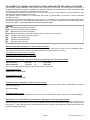
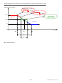
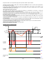
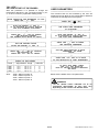
Sample diagram of the activation of a mixing valve with a 3-point, 6-10minute servo valve
% Mixing Valve Opening
maximum ton = 20 sec.
tof = 10 sec.
ton = 4 sec.
tof = 10 sec.
100%
Opening
50%
Closure
0%
Br40
TD
50
Br+
Td (°C)
60
Bp
Br
Note: chart not to scale.
16/36
RKP01M0001SE 024351 111214
ADJUSTMENT WITH SINGLE OR TWO STAGE BURNERS
The climate regulator manages burners with one or two stages. In the latter case, the burners operate for most of the
days during which heating is needed on the first stage (base load). In the case of low outside temperatures that
directly affect the supply water temperature, the burner switches to the second stage (greater heating). The system
adapts instantly to the new heat demand.
This two stage technology guarantees an optimal adjustment of the burner to external weather conditions.
LEGEND:
TD:
∆TD:
TDC:
Td:
tb1:
tb2:
to1:
to2:
calculated supply water temperature
hysteresis of the burner
compensated supply water temperature
measured supply water temperature
minimum ignition time of burner 1, set in the parameter "tb1"
minimum ignition time of burner 2, set in the parameter "tb2"
minimum extinction time of burner 1, set in the parameter "to1"
minimum extinction time of burner 2, set in the parameter "to2"
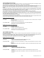
SINGLE-STAGE BURNER
Flame adjustment
Burner ON if Td ≤ (TD - ∆TD)
=>
Minimum ignition time of burner 1 = tb1.
Burner OFF if Td ≥ TD
=>
Minimum extinction time of burner 1 = to1.
BURNER ON
∆TD
Note:
If compensation is made by means
of the ambient temperature probe,
insert the value TDC instead of TD.
BURNER OFF
(TD - ∆TD)
TD
Td °C
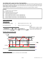
Activation chart as a function of time
Td (°C)
TDM
∆TD
TD
tb1
to1
tb1
to1
TIME
ON
BURNER
OFF
ON
CIRCULATION PUMP
OFF
Circulation pump control
The circulation pump will always be on, unless the unit is switched "OFF".
17/36
RKP01M0001SE 024351 111214
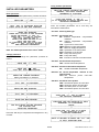
TWO-STAGE BURNER
By using a burner with two separate stages, the adjustment of the two flames is carried out separately.
Adjustment of first flame
The value of the activation differential of the first flame is equal to the value set in the parameter "∆TD" divided by 2,
Therefore we get:
First Flame ON
if
Td ≤ TD -
First Flame OFF
if
Td ≥ TD
First Flame ON
58,5
TD -
Example
∆TD
2
∆TD
2
=>
Minimum activation tb1 (in sec.)
=>
Minimum deactivation to1 (in sec.)
60°C
First Flame OFF
∆TD
2
TD
Td °C
∆TD = 3°C set in the installer parameter "burner hysteresis"
TD = Supply temperature calculated by the unit, for example 60°C.
∆TD (3°:2) = 1,5°C 60°C - 1,5 = 58,5°C
first flame ON
2
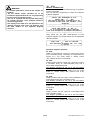
Adjustment of second flame
The second stage of the burner is activated only if the external temperature goes below a certain value, since the
external temperature directly affects the supply temperature, causing it to drop. The activation differential of the
second flame is equal to the value set in parameter "∆TD", whereas for deactivation the value ∆TD/2 is considered.
In particular we get:
Second Flame ON if
Td ≤ (TD - ∆TD)
=>
Minimum activation tb2 (in sec.)
Second Flame OFF if
∆TD
Td ≥ TD 2
=>
Minimum deactivation to2 (in sec.)
Second Flame ON
∆TD
2
57°C
1,5°C
(TD - ∆TD)
(60°C - 3°C = 57°C)
First Flame ON
∆TD
2
60°C
1,5°C
TD - ∆TD
2
(60°C - 1,5°C = 58,5°C)
First Flame OFF
TD
(calculated
supply T.)
Td °C
(temperature measured
by the supply probe)
Circulation pump control
The circulation pump will always be on, unless the unit is switched "OFF".
a WARNING
When managing the burners, both with one stage and with two stages, the following considerations must be
taken into account.
Minimum ignition and extinction time of the burners
To avoid that ignitions and extinctions of the burners are too short and cause them to get blocked, set the minimum
ignition and extinction time of the burners.
For the appropriate time, refer to the manual or the manufacturer of the boiler and set them using the dedicated
installer parameters P2: "tb1", "to1" and "tb2", "to2".
Adjustment of burners and pumps in the event that the unit is switched OFF
When the unit is switched off, the burner turns off and after the "pump OFF delay" time set in the installer parameter
P2 - "DEL", the circulation pump is deactivated.
Intervention of the minimum time, exceeded TD
As a result of the presence of a minimum ignition time for the burner "tb1" or "tb2", the calculated supply water
18/36
RKP01M0001SE 024351 111214
temperature "TD" or the compensated supply water temperature "TDC" maybe exceeded.
Therefore, the values of "tb1" or "tb2", "to1" or "to2", TD, and TDM must be set in a manner that is appropriate to
the characteristics of the system.
If you want to avoid exceeding the TD, you must set the value of tb1 to the minimum. This, however, is not
recommended because it may cause the burners to get blocked; the minimum settable value must be verified
considering the characteristics of the burner.
Anti-condensation function of burner
The easiest and least expensive way to prevent the formation of condensation in the boiler is t control the
temperature detected by the return water temperature "Tr".
This function will be activated if the probe "Tr" has been connected to the unit and if the value of the anticondensation temperature, set in the dedicated installer parameter in P2 - "TAC", will be different from OFF.
If the probe "Tr" has not been connected, the icon "Tr" and the circuit of the recirculation pump will not appear in
the hydraulic diagram on the display.
On the contrary, if the probe has been connected, but the value of "TAC" has been set to OFF, the icon "Tr" and the
circuit of the recirculation pump will flash.
To prevent the formation of condensation in the boiler, the temperature controlled by the probe "Tr", must always
remain above 55°C.
If a reasonable value is set for the minimum temperature of the supply water "TDL", the anti-condensation function is
carried out indirectly by the normal adjustment and conservation of that parameter.
In a climate control system, the activation of the anti-condensation function may occur in two different situations:
1) Upon start-up or after being off during the night.
2) During normal operation after changes in the thermal load.
In both cases, the behaviour is the same.
Activation chart as a function of time
Td (°C)
∆TD
2
TD
TD - ∆TD
2
∆TD
TD -∆TD
Time
ON
BURNER
STAGE 1
OFF
ON
BURNER
STAGE 2
OFF
ON
CIRCULATION
PUMP
OFF
19/36
RKP01M0001SE 024351 111214
ANTICONDENSATE FUNCTION
The anticondensate function, if enabled, allows to maintain, for the entire time that the system is managed, the return
water temperature in the boiler at the desired value, in order to avoid condensation.
With the use of the temperature probe, "Tr", the conservation of the return water temperature at the value set for the
anti-condensation temperature "TAC" (installer parameter P4) is guaranteed, with no significant deviations.
Maintaining the minimum temperature of the return water at a constant value does not affect the operating time of the
system.
Avoiding the condensation of the fumes inside the boilers is needed to prevent the rapid deterioration of the boilers
themselves due to the fact that the condensation of the fumes is very acidic la (the water binds with the sulphur and
forms sulphuric acid) and can easily attack the boiler body, until it is unusable.
The only boilers immune from these dangers are those that use condensation for energy optimization.
Normal boilers, not designed to exploit the latent heat of vaporization, need to be protected with devices that are able
to prevent the return water temperature from dropping below 55÷60°C. In fact, if the return water temperature is
below 55°C the fumes condense in the boiler.
The "Anticondensate Pump" has the aim to send part of the warm supply water directly to the return circuit, so as to
increase the return water temperature more quickly.
A good adjustment depends on the exact dimensioning of the anticondensate pump and of the system itself, as well
as the use of a boiler with suitable characteristics and with all its thermal data correctly set.
System with 3-point servo motor:
If Tr ≤ TAC:
- The servo motor will be closed with a pulse equal to Imax, so that the flow is conveyed
towards the return.
- Activation of the anticondensate pump.
If Tr ≥ (TAC + HYS):
- The servo motor can be opened/closed, as in climate adjustment
- Deactivation of the anticondensate pump.
System with a single or two-stage burner:
If Tr ≤ TAC:
- Activation of the burner.
- Activation of the anticondensate pump.
If Tr ≥ (TAC + HYS):
- The burner will be controlled as in climate control.
- Deactivation of the anticondensate pump.
ANTI-FREEZE FUNCTION
The anti-freeze function, if enables, allows to maintain the supply water temperature at the desired value, to prevent
the freezing of the piping.
With the use of the temperature probe, "Td", the conservation of the supply water temperature at the value set for the
anti-freeze temperature "TAF" (installer parameter P2) is guaranteed, with no significant deviations.
The activation of the function is signalled by the anti-freeze icon "n" appearing on the display.
System with 3-point servo motor:
If Td ≤ TAF:
- The servo motor will be opened with a pulse equal to Imax.
- If OFF, the circulation pump will be activated.
If Td ≥ (TAf + HYS):
- The servo motor will be controlled as in climate control associated to the logic of active
operation.
- The circulation pump will be controlled as in climate control associated to the logic of active
operation.
System with a single or two-stage burner:
If Td ≤ TAF:
- Activation of the first stage of the burner.
- If OFF, the circulation pump will be activated..
If Td ≥ (TAf + HYS):
- The burner will be controlled as in climate control associated to the logic of active
operation.
- The circulation pump will be controlled as in climate control associated to the logic of active
operation.
20/36
RKP01M0001SE 024351 111214
────────────────────────────
START-UP
────────────────────────────
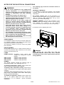
DISPLAY INFORMATION
The following image shows the display with all the
segments on:
DESCRIPTION OF CONTROLS
SELECTION KEYS
Display hydraulic diagram:
Probe icon.
Ta Te Icon on: probe present
Icon + symbol '
' flashing: probe faulty or
Td Tr not connected (if required as Te and Td)
Icon off: probe not present
RESET
KEY
Circulation pump:
Symbol on: pump off
Symbol flashing: pump on.
Symbol off: pump not needed for the current
setting.
ENTER KEY
(CONFIRM)
MENU
KEY
CANCEL
KEY
MANUAL
KEY
SEQUENCE OF OPERATIONS TO BE PERFORMED
FOR THE CORRECT START-UP OF THE RKP
CLIMATE CONTROL UNIT
Valve with 3-point servo motor:
The word 'OPEN' on: servo motor opening
The word 'CLOSE' on: servo motor closing
The word "OPEN"/"CLOSE" off: servo motor off
Functional features of the keys;
Esc
mano
▲
▼
Mj
•
Confirm
Exit
Comfort constant until 24:00
Scroll menu up
Scroll menu down
Menu
Perform the electrical connections
according to the chosen diagram.
Display additional information:
INT
Enable control via internal chronothermostat
EXT Enable control via External Contact
Temperature control in Comfort mode
l
correctly
Temperature control in Economy mode
Thermostat off, OFF mode
•
Turn on the unit by pressing and holding the "Esc"
button for at least 3 seconds.
Anti-freeze mode on, the thermostat controls the antifreeze temperature
•
Press the " " key once and insert password (default
password 0000)
1 / 2 stage burner ON/OFF:
Flame flashing: Burner on
Flame on: Burner off
•
Press the " " key 4 times to confirm the original
password "0000" (To change the password see the
paragraph "change password").
There is a fault in the system
The initials SCH will appear (diagrams)
"P1" (parameter 1). To select the chosen hydraulic
diagram, press the "
" key again, then use the
arrows "▲" and "▼" to scroll through the 4 hydraulic
diagrams suggested.
Icon on: the CUT-OFF function has been enabled
Icon off: the CUT-OFF function is not enabled
•
•
Pres the " " key to confirm, or press "Esc" to cancel
the selection.
The climate regulator is in Programming mode
SWITCHING ON AND OFF
To turn the unit on and off press and hold the ' esc ' key
for at least 3 seconds.
When turned on, the unit will make a diagnosis of the
internal circuit to check that it works correctly and the
red LED will flash 3 times.
If the unit does not detect any faults, the red LED will
remain lit; otherwise the red LED will flash rapidly and
the type of error will appear on the display.
When turned off, the word 'OFF' is displayed.
21/36
RKP01M0001SE 024351 111214
DISPLAY TEMPERATURE / CLOCK
The unit is able to show on the alphanumeric display
the current time and date and the temperatures detected
by the various probes connected.
By using the keys '▲' and '▼' you can scroll through the
data provided.
Example of clock displayed:
10:53 (hour:minutes)
Mon (day of the week)
Example of temperature displayed:
20.0°C (temperature expressed in degrees centigrade)
T_x (probe connected measuring temperature - Te, Td,
Tr, Ta)
STATUS OF OUTPUTS
The outputs OUT 1, OUT 2, OUT 3 and PUMP relative
to the loads connected to the unit in the status "FAULT",
will be N.O. (normally open).
When normal operation is restored, the unit may control
the output of the servo motor during closing for a pulse
equal to the maximum, that is 6 minutes or 11 minutes
depending on the type of servo motor used.
This function aims to restore the servo motor in safety
position (closing and consequently a lowering of the
supply temperature). With the servo motor back in
place, the unit will resume normal operation.
When the unit is off, the word "OFF" will be displayed. If
the anti-freeze function has been activated, the icon " "
will be displayed and the unit will adjust the ambient
temperature according to the anti-freeze temperature
set.
MANUAL 24h SETTINGS
With the " " key, the unit can be forced to adjust the
ambient temperature regardless of the time settings,
according to the comfort temperature set.
By pressing the "
" key repeatedly, the unit goes from
Automatic to Manual 24h mode and vice versa.
During operation in "Manual 24h" the symbol "
" will
be displayed and all the segments of the time setting will
be on (a flashing segment indicated the current time).
By pressing the "m" key once, Manual 24h mode is
activated and the climate control unit remains in manual
mode until 23:59, after which operation according to the
program previously set in the parameter "SFM U1" is
restored.
The function "MANUAL 24h" cannot be activated if the
unit is operating in "COMF" mode, settable in the
parameter "SFM U1".
Display Manual 24h mode
The unit adjusts the ambient temperature, in comfort mode,
until 23:59.
After which the program previously set in the parameter
"SFM U1" is restored.
The flashing segment indicates the current time
RESET
To reset the device press the " RESET " key located
under the removable; DO NOT USE NEEDLES.
22/36
RKP01M0001SE 024351 111214
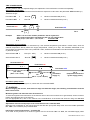
Using installer parameters
────────────────────────────
INSTALLER PARAMETERS
────────────────────────────
┌──────────────────────────────────────┐
│ ONCE THE CORRECT PASSWORD HAS BEEN │
│
ENTERED, THE FIRST INSTALLER
│
│
PARAMETER IS DISPLAYED
│
└──────────────────────────────────────┘
Enter password
To access the installer parameters, proceed as follows:
┌──────────────────────────────────────┐
│
USING THE ARROWS '▼' AND '▲'
│
│IT IS POSSIBLE TO SCROLL THROUGH THE │
│
INSTALLER PARAMETERS.
│
└──────────────────────────────────────┘
┌──────────────────────────────────────┐
│
PRESS THE ‘
’ KEY.
│
└──────────────────────────────────────┘
┌──────────────────────────────────────┐
│ ‘0000 PWD' IS DISPLAYED WITH THE
│
│ FIRST DIGIT ON THE LEFT FLASHING.
│
└──────────────────────────────────────┘
Note: the installer parameters are 6 and they are
described in detail below:
┌──────────────────────────────────────┐
│
ENTER THE PASSWORD.
│
│ ENTER THE 4 DIGITS OF THE PASSWORD │
│
USING THE ARROWS '▼' AND '▲'.
│
│
PRESS THE '
' KEY TO CONFIRM
│
│
THE DIGIT INSERTED AND TO
│
│
SELECT THE NEXT ONE AND SO ON
│
│
UNTIL THE LAST ONE.
│
│ BY CONFIRMING THE LAST DIGIT WITH
│
│
THE '
' KEY, YOU WILL ACCESS
│
│
THE INSTALLER PARAMETERS.
│
└──────────────────────────────────────┘
"P1 SCH" Select system type
Note: the default password of the unit is ’0000'.
Change password
Of you want to change the password, proceed as
follows:
"P2 DAT" Set system data
KS: External temperature compensation
coefficient
KA: Ambient temperature compensation
coefficient
TYP: Type of servo motor used
TDM: Maximum supply temperature
TDL: Minimum supply temperature
HYS: Hysteresis of the thermostats
∆TD: Hysteresis of the burners
TAL: Pump anti-locking time
DEL: Pump OFF delay
PRI: Internal or external chronothermostat
┌──────────────────────────────────────┐
│
PRESS THE ‘
’ KEY.
│
└──────────────────────────────────────┘
"P3 OAF" Set anti-freeze temperature
TAF: Set anti-freeze temperature
┌──────────────────────────────────────┐
│
PRESS THE ‘ Mj ’ KEY.
│
│
’0000 PW0’ WILL BE DISPLAYED.
│
└──────────────────────────────────────┘
"P4 OAC" Set anti-condensation temperature
KS: Set anti-condensation temperature
"P5 OCO" Se cut-off temperature referred to the
external probe
TCO: Set external probe CUT-OFF
temperature
┌──────────────────────────────────────┐
│
ENTER THE CURRENT PASSWORD.
│
│
Same procedure as before.
│
└──────────────────────────────────────┘
"P6 OFS": Set offset of the probes
OFE: Set external probe "Te" OFF-SET
OFD: Set supply probe "Td" OFF-SET
OFR: Set return probe "Tr" OFF-SET
OFA: Set ambient probe "Ta" OFF-SET
┌──────────────────────────────────────┐
│
'0000 PW0' IS DISPLAYED.
│
└──────────────────────────────────────┘
┌──────────────────────────────────────┐
│
ENTER THE NEW PASSWORD.
│
└──────────────────────────────────────┘
┌──────────────────────────────────────┐
│
'0000 PW0' IS DISPLAYED.
│
└──────────────────────────────────────┘
┌──────────────────────────────────────┐
│
PRESS THE '
' KEY TO CHANGE
│
│
THE SELECTED PARAMETER.
│
└──────────────────────────────────────┘
┌──────────────────────────────────────┐
│
ENTER THE NEW PASSWORD.
│
└──────────────────────────────────────┘
┌──────────────────────────────────────┐
│ CONFIGURE THE DATA RELATIVE TO EACH │
│
PARAMETER, AS ILLUSTRATED
│
│
BELOW.
│
└──────────────────────────────────────┘
┌──────────────────────────────────────┐
│
THE UNIT SAVES THE NEW PASSWORD
│
│
AND ACCESSES THE
│
│
INSTALLER PARAMETERS.
│
└──────────────────────────────────────┘
Press the 'esc' key to exit password management in any
moment.
┌──────────────────────────────────────┐
│
PRESS THE 'esc' KEY TO GO BACK
│
│
TO THE SELECTION OF THE
│
│
INSTALLER PARAMETERS.
│
└──────────────────────────────────────┘
┌──────────────────────────────────────┐
│WAIT 20 SECONDS OR PRESS THE ‘esc’ KEY│
│
TO EXIT INSTALLER MODE.
│
└──────────────────────────────────────┘
23/36
RKP01M0001SE 024351 111214
"P1
WARNING!
- In "installer parameters" mode all the outputs are
disabled.
- All the default values indicated are to be
considered approximate and can vary depending
on the version and without notice.
- The unit is supplied with the thermal data preset
for optimal operation. Only qualified personnel
should change these .
- The display of the data to be set depends on the
diagram selected, that is the unit displays only
the data relative to the hydraulic diagram
selected.
SCH"
SELECT SYSTEM TYPE
With this parameter you can select the type of hydraulic
system to be made.
The unit offers the opportunity to select four different
hydraulic diagrams.
┌──────────────────────────────────────┐
│
SELECT THE PARAMETER'P1 SCH'
│
│
PRESS THE ’
' KEY;
│
│ THE ACTIVE HYDRAULC DIAGRAM WILL BE │
│ DISLAYED ALONG WITH THE LETTERS 'SCH'│
│
FLASHING.
│
└──────────────────────────────────────┘
┌──────────────────────────────────────┐
│
USING THE ARROWS '▼' AND '▲'
│
│
IT IS POSSIBLE TO SCROLL THROUGH
│
│THE FOUR HYDRAULIC DIAGRAMS AVAILABLE.│
└──────────────────────────────────────┘
Note: below are the main characteristics of each
hydraulic diagram. For further details see the paragraph
'INSTALLATION'.
┌──────────────────────────────────────┐
│
PRESS THE '
' KEY TO CORFIRM
│
│
THE SETTINGS OR PRESS THE ’esc’ KEY│
│
TO CANCEL.
│
└──────────────────────────────────────┘
Hydraulic diagrams available:
01 SCH:
Heating system with the control of a 3-point servo motor
and a circulation pump. Possibility of compensation by
means of a "Ta" probe and/or a remote control
"RC" (neither have to be connected).
02 SCH:
Heating system with the control of a 3-point servo motor,
a circulation pump, an anticondensate pump and a
return water temperature probe.
This diagram provides for the use of the recirculation
pump and the return probe -.Tr.
Possibility of compensation by means of a "Ta" probe
and/or a remote control "RC" (neither have to be
connected).
03 SCH:
Heating system with the 2-point control (ON/OFF) of a
single stage burner and a circulation pump.
This diagram provides for the use of the recirculation
pump and the return probe -.Tr.
Possibility of compensation by means of a "Ta" probe
and/or a remote control "RC" (neither have to be
connected).
04 SCH:
Heating system with the control of a two-stage burner
and a circulation pump.
This diagram provides for the use of the recirculation
pump and the return probe -.Tr.
Possibility of compensation by means of a "Ta" probe
and/or a remote control "RC" (neither have to be
connected).
24/36
RKP01M0001SE 024351 111214
"P2 DAT"
SYSTEM DATA SETTINGS
With this parameter you can set all the data that
influence the management of the hydraulic system.
┌──────────────────────────────────────┐
│ ONCE YOU HAVE SELECTED THE ’P2 DAT’ │
│
PARAMETER, PRESS THE ’
’ KEY. │
└──────────────────────────────────────┘
┌──────────────────────────────────────┐
│
USING THE ARROWS '▼' AND '▲'
│
│
IT IS POSSIBLE TO SCROLL THROUGH
│
│
THE FOURTEEN ELEMENTS AVAILABLE. │
└──────────────────────────────────────┘
┌─────────────────────────────────────┐
│
MINIMUM TEMPERATURE OF
│
│
SUPPLY WATER
│
│—————————————————————————————————————│
│ Data │ Adjustment range │ Default │
│——————│————————————————————│—————————│
│ TDL │ OFF 5.0 .. 90.0 °C │
OFF
│
└─────────────────────────────────────┘
Note: this parameter defines the minimum temperature
of the supply water.
The value of TDL cannot be set at a value above that of
TDM - 5°C.
To disable this function, set the parameter to "OFF".
Note: below are the details of the data available.
┌──────────────────────────────────────┐
│
PRESS THE '
' KEY TO MODIFY
│
│
THE ELEMENT SELECTED.
│
│
THE ELEMENT BEGINS TO FLASH.
│
└──────────────────────────────────────┘
┌──────────────────────────────────────┐
│
SET THE DESIRED VALUE
│
│
USING THE ARROWS '▼' AND '▲'.
│
└──────────────────────────────────────┘
┌──────────────────────────────────────┐
│
PRESS THE ’
' KEY TO CONFIRM
│
│
THE SETTINGS OR
│
│
PRESS THE 'esc' KEY TO CANCEL.
│
│
│
└──────────────────────────────────────┘
┌─────────────────────────────────────┐
│
EXTERNAL TEMPERATURE
│
│
COMPENSATION COEFFICIENT
│
│—————————————————————————————————————│
│ Data │ Adjustment range │ Default │
│——————│————————————————————│—————————│
│ KS │
0.5 .. 5
│
2.0
│
└─────────────────────────────────────┘
Note: this parameter determines the speed of response
of the entire system on the basis of the changes in the
outside temperature detected by the probe "Te".
For more details, see the paragraph "Operating
principles of the climate regulator" on page 14.
┌─────────────────────────────────────┐
│
AMBIENT TEMPERATURE
│
│
COMPENSATION COEFFICIENT
│
│—————————————————————————————————————│
│ Data │ Adjustment range │ Default │
│——————│————————————————————│—————————│
│ KA │
0.5 .. 5
│
2.0
│
└─────────────────────────────────────┘
Note: this parameter determines the compensation
coefficient depending on the ambient temperature
detected by the probe "Ta".
For more details, see the paragraph "Operating
principles of the climate regulator - Compensation with
ambient temperature" on page 14.
┌─────────────────────────────────────┐
│
TYPE OF SERVO MOTOR USED
│
│—————————————————————————————————————│
│ Data │ Adjustment range │ Default │
│——————│————————————————————│—————————│
│ TYP │
3 .. 5 min.
│ 3 .. 5 │
│
│
6 .. 10 min.
│
min. │
└─────────────────────────────────────┘
┌─────────────────────────────────────┐
│
MAXIMUM TEMPERATURE OF
│
│
SUPPLY WATER
│
│—————————————————————————————————————│
│ Data │ Adjustment range │ Default │
│——————│————————————————————│—————————│
│ TDM │OFF 95.0 .. 10.0 °C │
OFF
│
└─────────────────────────────────────┘
Note: this parameter defines the maximum temperature
of the supply water.
The value of TDM cannot be set at a value below that of
TDL + 5°C.
To disable this function, set the parameter to "OFF".
┌─────────────────────────────────────┐
│
HYSTERESIS OF THE THERMOSTATS
│
│—————————————————————————————————————│
│ Data │ Adjustment range │ Default │
│——————│————————————————————│—————————│
│ HYS │
not adjustable
│ 1.0°C │
└─────────────────────────────────────┘
┌─────────────────────────────────────┐
│
HYSTERESIS OF THE BURNER
│
│—————————————————————————————————————│
│ Data │ Adjustment range │ Default │
│——————│————————————————————│—————————│
│ ∆TD │
0.5 .. 25.0 °C
│ 3.0°C │
└─────────────────────────────────────┘
┌─────────────────────────────────────┐
│ HYSTERESIS OF THE ANTI-CONDENSATION │
│
THERMOSTATAT
│
│—————————————————————————————————————│
│ Data │ Adjustment range │ Default │
│——————│————————————————————│—————————│
│ HYS │
0.5 .. 10.0 °C
│ 1.0°C │
└─────────────────────────────────────┘
┌─────────────────────────────────────┐
│
PERIODIC ACTIVATION OF THE
│
│
CIRCULATION PUMP
│
│—————————————————————————————————————│
│ Data │ Adjustment range │ Default │
│——————│————————————————————│—————————│
│ TAL │OFF 5 .. 240.0 sec. │
OFF
│
└─────────────────────────────────────┘
Note: With the parameter "TAL" it is possible to select
the interval, in seconds, to activate the circulation water
pump in order to prevent it from getting blocked.
The circulation pump, if the parameter "TAL" is enabled,
will be activated every 23 hours if there have not been
previous activations.
To disable this function, set the parameter to "OFF".
┌─────────────────────────────────────┐
│
CIRCULATION PUMP OFF DELAY
│
│
│
│—————————————————————————————————————│
│ Data │ Adjustment range │ Default │
│——————│————————————————————│—————————│
│ DEL │ OFF 1 .. 30 min. │
OFF
│
└─────────────────────────────────────┘
Note: With this parameter, if enabled, it is possible to set
the time, in minutes, of delay for the circulation pump to
turn off in order to avoid sudden start-ups.
To disable this function, set the parameter to "OFF".
25/36
RKP01M0001SE 024351 111214
┌─────────────────────────────────────┐
│
MINIMUM IGNITION BURNER 1
│
│—————————————————————————————————————│
│ Data │ Adjustment range │ Default │
│——————│————————————————————│—————————│
│ tb1 │ OFF 1 .. 250 sec. │ 60 sec. │
└─────────────────────────────────────┘
To disable this function, set the parameter to "OFF".
"P3 OAF"
SETTING ANTI-FREEZE TEMPERATURE
┌─────────────────────────────────────┐
│
MINIMUM EXTINCTION BURNER 1
│
│—————————————————————————————————————│
│ Data │ Adjustment range │ Default │
│——————│————————————————————│—————————│
│ tO1 │ OFF 1 .. 250 sec. │ 60 sec. │
└─────────────────────────────────────┘
To disable this function, set the parameter to "OFF".
┌──────────────────────────────────────┐
│AFTER SELECTING THE PARAMETER 'P3 OAF'│
│
PRESS THE '
' KEY.
│
│ THE ELEMENT ‘TAF' WILL BE DISPLAYED; │
│
THEN PRESS THE '
'KEY AGAIN;
│
│
'TAF' WILL FLASH ON THE DISPLAY.
│
│
│
└──────────────────────────────────────┘
This parameter allows you to set the anti-freeze
temperature to protect the system if the supply water
temperature drops below the value set.
To disable this function, set the parameter to "OFF".
┌─────────────────────────────────────┐
│
MINIMUM IGNITION BURNER 2
│
│—————————————————————————————————————│
│ Data │ Adjustment range │ Default │
│——————│————————————————————│—————————│
│ tb2 │ OFF 1 .. 250 sec. │ 60 sec. │
└─────────────────────────────────────┘
Note: It is not possible to set the value of tb2 to a value
higher than the value of tb1, because the value of tb2 is
limited to the value of tb1.
If you want to increase the value of tb2, you must
increase the value of tb1 first, according to the relation:
tb2 ≤ tb1.
To disable this function, set the parameter to "OFF".
┌─────────────────────────────────────┐
│
MINIMUM EXTINCTION BURNER 2
│
│—————————————————————————————————————│
│ Data │ Adjustment range │ Default │
│——————│————————————————————│—————————│
│ tO2 │ OFF 1 .. 250 sec. │ 60 sec. │
└─────────────────────────────────────┘
Note: It is not possible to set the value of to2 to a value
lower than the value of to1, because the value of tb2 is
limited to the value of to1.
If you want to decrease the value of to2, you must
decrease the value of to1 first, according to the relation:
to2 ≥ to1.
To disable this function, set the parameter to "OFF".
┌──────────────────────────────────────┐
│
SET THE DESIRED VALUE
│
│
BY USING THE ARROWS '▼' AND '▲'. │
└──────────────────────────────────────┘
┌──────────────────────────────────────┐
│
PRESS THE '
' KEY TO CONFIRM
│
│ THE SETTINGS OR PRESS THE ’esc’ KEY │
│
TO CANCEL.
│
│
│
└──────────────────────────────────────┘
┌─────────────────────────────────────┐
│
ANTI-FREEZE TEMPERATURE
│
│—————————————————————————————————————│
│ Data │ Adjustment range │ Default │
│——————│————————————————————│—————————│
│ TAF │
OFF 1 .. 40 °C
│
5 °C │
└─────────────────────────────────────┘
To disable this function, set the parameter to "OFF".
┌─────────────────────────────────────┐
│
ADJUSTMENT ON INTERNAL
│
│
CHRONOTHERMOSTAT (INt) OR
│
│
ON EXTERNAL CONTACT (EHt)
│
│—————————————————————————————————————│
│ Data │ Adjustment range │ Default │
│——————│————————————————————│—————————│
│ PRI │
INT .. EHt
│
INt
│
└─────────────────────────────────────┘
Note: Setting the parameter to "EXT", external contact,
will make the icon "hEXT" light up on the display,
whereas setting the parameter to "INT", adjustment
according to the program inside the unit, will make the
icon "hINT" light up on the display.
26/36
RKP01M0001SE 024351 111214
"P4 OAC"
SETTING
ANTI -CONDE NS ATI ON
TEMPERATURE
"P5 OCO"
SETTING THE CUT-OFF TEMPERATURE
REFERRED TO THE EXTERNAL PROBE
This parameter allows you to control the temperature
detected by the probe "Tr" (return water temperature
probe) so as to avoid the formation of condensation in
the boiler.
To disable this function, set the parameter to "OFF".
For more details see the paragraph "Adjustment with
single or two stage burners'.
This parameter, if enabled, allows for the system to be
turned off when the temperature detected by the probe
Te (external temperature probe) exceeds the value set
in the parameter "TCO".
To disable this function, set the parameter to "OFF".
┌──────────────────────────────────────┐
│AFTER SELECTING THE PARAMETER 'P4 OAC'│
│
PRESS THE '
' KEY.
│
│ THE ELEMENT 'TAC' WILL BE DISPLAYED; │
│
PRESS THE ’
’ KEY AGAIN;
│
│
TAC' WILL FLASH ON THE DISPLAY.
│
│
│
└──────────────────────────────────────┘
┌──────────────────────────────────────┐
│
SET THE DESIRED VALUE
│
│
BY USING THE ARROWS '▼' AND '▲'. │
└──────────────────────────────────────┘
┌──────────────────────────────────────┐
│
PRESS THE '
' KEY TO CONFIRM
│
│ THE SETTINGS OR PRESS THE ’esc’ KEY │
│
TO CANCEL.
│
│
│
└──────────────────────────────────────┘
┌─────────────────────────────────────┐
│
ANTI-CONDENSATION TEMPERATURE
│
│—————————————————————————————————————│
│ Data │ Adjustment range │ Default │
│——————│————————————————————│—————————│
│ TAC │OFF 10.0 .. 95.0 °C │ 60 °C │
└─────────────────────────────────────┘
┌──────────────────────────────────────┐
│AFTER SELECTING THE PARAMETER 'P5 OCO'│
│
PRESS THE '
' KEY.
│
│ THE ELEMENT 'TCO' WILL BE DISPLAYED; │
│
PRESS THE '
' KEY AGAIN
│
│ 'TCO' WILL FLASH ON THE DISPLAY.
│
│
│
└──────────────────────────────────────┘
┌──────────────────────────────────────┐
│
SET THE DESIRED VALUE
│
│
BY USING THE ARROWS '▼' AND '▲'. │
└──────────────────────────────────────┘
┌──────────────────────────────────────┐
│
PRESS THE '
' KEY TO CONFIRM
│
│ THE SETTINGS OR PRESS THE ’esc’ KEY │
│
TO CANCEL.
│
│
│
└──────────────────────────────────────┘
┌─────────────────────────────────────┐
│
CUT-OFF TEMPERATURE
│
│—————————————————————————————————————│
│ Data │ Adjustment range │ Default │
│——————│————————————————————│—————————│
│ TCO │OFF 10.0 .. 50.0 °C │
OFF
│
└─────────────────────────────────────┘
Ti disable this function, set the parameter to "OFF".
To disable this function, set the parameter to "OFF".
27/36
RKP01M0001SE 024351 111214
"P6 OFS"
SETTING OFFSET OF THE PROBES
With this parameter it is possible to change the
temperature detected by the connected probes, by ±5°
C, so as to correct any systematic reading errors.
┌──────────────────────────────────────┐
│AFTER SELECTING THE PARAMETER 'P6 OFS'│
│
PRESS THE '
' KEY;
│
└──────────────────────────────────────┘
┌──────────────────────────────────────┐
│
WITH THE ARROWS '▼' AND '▲'
│
│
IT IS POSSIBLE TO SCROLL THROUGH
│
│
THE FOUR ELEMENTS AVAILABLE.
│
└──────────────────────────────────────┘
┌──────────────────────────────────────┐
│
PRESS THE '
' KEY TO CHANGE
│
│
THE SELECTED ELEMENT.
│
│
THE ELEMENT WILL BEGIN TO FLASH.
│
└──────────────────────────────────────┘
┌──────────────────────────────────────┐
│
SET THE DESIRED VALUE
│
│
USING THE ARROWS '▼' AND '▲'.
│
└──────────────────────────────────────┘
┌──────────────────────────────────────┐
│
PRESS THE '
' KEY TO CONFIRM
│
│
THE SETTINGS OR
│
│
PRESS THE ’esc’ KEY TO CANCEL
│
│
│
└──────────────────────────────────────┘
┌─────────────────────────────────────┐
│
OFFSET OF THE PROBES
│
│—————————————————————————————————————│
│ Data │ Adjustment range │ Default │
│——————│————————————————————│—————————│
│ OFE │ -5.0 .. +5.0 °C
│
0
│
│ OFD │ -5.0 .. +5.0 °C
│
0
│
│ OFR │ -5.0 .. +5.0 °C
│
0
│
│ OFA │ -5.0 .. +5.0 °C
│
0
│
└─────────────────────────────────────┘
Note:
OFE = Offset on probe Te
OFD = Offset on probe Td
OFR = Offset on probe Tr
OFA = Offset on probe Ta
────────────────────────────
USER PARAMETERS
────────────────────────────
The functions that can be accessed by the user are
limited and do not allow for the configuration of data that
influences the management of the system.
┌──────────────────────────────────────┐
│
PRESS THE ‘
’ KEY.
│
└──────────────────────────────────────┘
┌──────────────────────────────────────┐
│
THE FIRST USER PARAMETER
│
│
IS DISPLAYED.
│
└──────────────────────────────────────┘
┌──────────────────────────────────────┐
│
WITH THE ARROWS '▼' AND '▲'
│
│
IT IS POSSIBLE TO SCROLL THROUGH
│
│
THE FIVE USER PARAMETERS.
│
└──────────────────────────────────────┘
┌──────────────────────────────────────┐
│
PRESS THE ' ' KEY TO ENTER
│
│
THE SELECTED PARAMETER.
│
└──────────────────────────────────────┘
┌──────────────────────────────────────┐
│
SET THE DATA RELATIVE TO EACH
│
│
PARAMETER, AS SHOWN
│
│
BELOW.
│
└──────────────────────────────────────┘
┌──────────────────────────────────────┐
│
PRESS THE 'esc' KEY TO GO BACK
│
│ TO THE SELECTION OF USER PARAMETERS. │
└──────────────────────────────────────┘
┌──────────────────────────────────────┐
│
TO EXIT THIS MENU, PRESS
│
│
THE 'esc' KEY AGAIN OR
│
│
WAIT 20 SECONDS WITHOUT PRESSING │
│
ANY KEYS.
│
└──────────────────────────────────────┘
Below are the details of the user parameters.
WARNING!
- All the default values indicated are to be
considered approximate as they may vary
depending on the version and without notice.
28/36
RKP01M0001SE 024351 111214
This parameter allows you to select the mode of
operation of the unit:
- 'Pr-1': Automatic Comfort-Economy mode (depending
on the parameter 'U3 PRG').
Display during normal operation
┌──────────────────────────────────────┐
│AFTER SELECTING THE PARAMETER 'U1 SFM'│
│
PRESS THE '
' KEY TWICE;
│
│
THE LETTERS 'SFM' WILL FLASH.
│
└──────────────────────────────────────┘
In the comfort time slots the unit will adjust the temperature according to the comfort temperature set "TC",
whereas during Economy time slots it will adjust the
temperature according to the Economy temperature set
"U1 SFM" - Selecting the Mode of Operation
┌──────────────────────────────────────┐
│
WITH THE ARROWS '▼' AND '▲'
│
│
IT IS POSSIBLE TO SCROLL THROUGH
│
│
THE FOUR MODES OF OPERATION.
│
└──────────────────────────────────────┘
- 'COMF': Comfort 24h mode.
Display during normal operation
Permanent exclusion of the program "COMF",
comfort 24h mode
The flashing segment indicates the current time
- 'Pr-2': Automatic Comfort-Off or Anti-freeze mode
(depending on the parameter 'U3 PRG').
Display during normal operation
In the comfort time slots the unit will adjust the
temperature according to the comfort temperature set
"TC", whereas during Economy time slots it will be
switched off or, if the anti-freeze function is enabled, it will
adjust the temperature according to the anti-freeze
temperature set "P3 OAF".
The flashing segment indicates the current time
- 'ECON': Economy 24h mode.
Display during normal operation
Permanent exclusion of the program "ECON",
Economy 24h mode
The flashing segment indicates the current time
The flashing segment indicates the current time
┌──────────────────────────────────────┐
│
PRESS THE '
' KEY TO CONFIRM
│
│
THE SETTINGS OR
│
│
PRESS THE 'esc' KEY TO CANCEL.
│
│
│
└──────────────────────────────────────┘
Table 1: Mode of operation depending on the settings of parameter U1
Adjustment level
Status
Parameter
U1
Status
management
l
Sun Moon
Optional functions
Off or Anti-freeze
Status
Anti-freeze
Off
Antifreeze
(
AntiCut-Off
condensation
if enabled)
( if enabled)
Anti-freeze
disabled
OFF
--
Manual
Anti-freeze
enabled
COMF
Manual
ECON
Manual
PR-1
Schedule
ON
Anti-freeze
disabled
PR-2
Schedule
Anti-freeze
enabled
29/36
RKP01M0001SE 024351 111214
"U2 MDY"
Date and time settings
This parameter allows you to adjust the date and time.
WARNING!
- The device manages the date for leap years
automatically.
- If the summer time/winter time adjustment is
active, but there is a power cut between 1:59:59
and 2:00:00, the transition from summer time to
winter time and vice versa may not be carried
out.
- The settings will be saved only after pressing the
'
' key in the last parameter available 'MEMO
CLK'.
- If you exit this parameter before managing the
last parameter 'MEMO CLK' or if the timeout
expires, the settings will not be saved.
┌──────────────────────────────────────┐
│AFTER SELECTING THE PARAMETER 'U2 MDY'│
│
PRESS THE '
' KEY;
│
│
THE LETTERS 'HH' WILL FLASH.
│
└──────────────────────────────────────┘
┌──────────────────────────────────────┐
│
USING THE ARROWS '▼' AND '▲'
│
│
YOU CAN SET THE CURRENT TIME.
│
└──────────────────────────────────────┘
┌──────────────────────────────────────┐
│
PRESS THE '
' KEY;
│
│
THE LETTERS 'MM' WILL FLASH.
│
└──────────────────────────────────────┘
┌──────────────────────────────────────┐
│
USING THE ARROWS '▼' AND '▲'
│
│
YOU CAN SET THE YEAR (1..99).
│
└──────────────────────────────────────┘
┌──────────────────────────────────────┐
│
PRESS THE '
' KEY;
│
│
THE LETTERS 'S-L' WILL FLASH.
│
└──────────────────────────────────────┘
┌──────────────────────────────────────┐
│
USING THE ARROWS '▼' AND '▲'
│
│YOU CAN SET THE TRANSITION FROM WINTER│
│ TIME TO SUMMER TIME AND VICE VERSA: │
│No:
THE TRANSITION WINTER/SUMMER
│
│
TIME IS NOT CARRIED OUT
│
│Aut: THE TRANSITION WINTER/SUMMER
│
│
TIME IS CARRIED OUT
│
│
AUTOMATICALLY.
|
└──────────────────────────────────────┘
┌──────────────────────────────────────┐
│
PRESS THE '
' KEY;
│
│ THE WORD ’MEMO’ WILL APPEAR ON THE │
│
DISPLAY WITH 'CLK' FLASHING.
│
└──────────────────────────────────────┘
┌──────────────────────────────────────┐
│
PRESS THE ' ' KEY AGAIN.
│
│
THE UNIT SAVES THE SETTINGS
│
│
AND THE SCREEN RELATIVE TO THE
│
│
TIME SETTINGS IS DISPLAYED
│
│
(TIME UPDATED)
│
│
WITH THE LETTERS ‘HH’
│
│
FLASHING.
|
└──────────────────────────────────────┘
┌──────────────────────────────────────┐
│
PRESS THE 'esc' KEY TO GO BACK
│
│ TO THE SELECTION OF USER PARAMETERS. │
└──────────────────────────────────────┘
┌──────────────────────────────────────┐
│
USING THE ARROWS '▼' AND '▲'
│
│
YOU CAN SET THE MINUTES.
│
└──────────────────────────────────────┘
┌──────────────────────────────────────┐
│
PRESS THE '
' KEY;
│
│
THE LETTERS ‘DWK’ WILL FLASH.
│
└──────────────────────────────────────┘
┌──────────────────────────────────────┐
│
USING THE ARROWS '▼' AND '▲'
│
│
YOU CAN SET THE DAY OF THE WEEK
│
│
(1 Monday .. 7 Sunday).
│
└──────────────────────────────────────┘
┌──────────────────────────────────────┐
│
PRESS THE '
' KEY;
│
│
THE LETTERS 'DAY' WILL FLASH.
│
└──────────────────────────────────────┘
┌──────────────────────────────────────┐
│
USING THE ARROWS '▼' AND '▲'
│
│
YOU CAN SET THE DAY (1..31)
│
└──────────────────────────────────────┘
┌──────────────────────────────────────┐
│
PRESS THE '
' KEY;
│
│
THE LETTERS 'MTH' WILL FLASH.
│
└──────────────────────────────────────┘
┌──────────────────────────────────────┐
│
USING THE ARROWS '▼' AND '▲'
│
│
YOU CAN SET THE DAY (1..12)
│
└──────────────────────────────────────┘
┌──────────────────────────────────────┐
│
PRESS THE '
' KEY;
│
│
THE LETTERS 'YEA' WILL FLASH.
│
└──────────────────────────────────────┘
30/36
RKP01M0001SE 024351 111214
"U3 PRG"
Setting the timer
This parameter, accessible only if the parameter 'U1' is
set to 'Pr-1' or to 'Pr-2', allows you to set the timer.
Usually the dashes at the bottom of the display show the
current mode of operation (Comfort, Economy, Off, Antifreeze) of the unit.
The flashing dash indicates you can set the current time.
To facilitate the programming operation, it is sufficient to
recall as follows:
Dash on:
- Comfort mode is enables ('
' icon on)
Dash off:
- Economy mode is enabled (' ' icon on), if U1 is set to
'Pr-1'.
- Off mode is enabled (' ' icon on) or Anti-freeze mode
('
' icon on), depending on the settings made in U4,
if U1 is set to 'Pr-2'.
l
To set the timer, proceed as described below.
┌──────────────────────────────────────┐
│AFTER SELECTING THE PARAMETER 'U3 PRG'│
│
PRESS THE '
' KEY;
│
│ THE LETTERS ‘GRP’ WILL BE DISPLAYED. │
└──────────────────────────────────────┘
┌──────────────────────────────────────┐
│ IF YOU WANT TO CHANGE THE GROUP OF │
│
DAYS SET, SELECT 'GRP'
│
│
AND PRESS THE '
' KEY.
│
└──────────────────────────────────────┘
┌──────────────────────────────────────┐
│USING THE ARROWS '▼' AND '▲' YOU CAN │
│
MOVE THE TIME CURSOR (EACH DASH
│
│ CORRISPONDS TO HALF AN HOUR) AND BY │
│
REPEATEDLY PRESSING THE ' m ' KEY
│
│
YOU CAN SET THE ADJUSTMENT MODE:
│
│COMFORT MODE:
'k' ICON ON
│
│ECONOMY MODE:
'l' ICON ON
│
│OFF MODE:
'o' ICON ON
│
│ANTI-FREEZE MODE: 'n' ICON ON
│
└──────────────────────────────────────┘
┌──────────────────────────────────────┐
│
THE LETTERS 'GRP' WILL FLASH
│
│
AND THE GROUP OF DAYS
│
│
SET.
│
└──────────────────────────────────────┘
┌──────────────────────────────────────┐
│
USING THE ARROWS '▼' AND '▲'
│
│
YOU CAN SELECT THE DESIRED GROUP
│
│
OF DAYS: G-1, G-2, ALL, SnG.
│
└──────────────────────────────────────┘
Note: Below are the four combinations of days available:
G-1: Monday .. Friday + Saturday .. Sunday
G-2: Monday .. Saturday + Sunday
ALL: Monday .. Sunday (the same every day)
SnG: Monday + Tuesday + Wednesday + Thursday +
Friday + Saturday + Sunday (different every day)
WARNING!
For each group of days, the program set will be the
same for each day of that group.
┌──────────────────────────────────────┐
│
USING THE ARROWS '▼' AND '▲'
│
│
YOU CAN SCROLL THROUGH THE PRESET │
│
PROGRAMS RELATIVE TO THE
│
│
COMBINATION OF DAYS SELECTED:
│
│
P_1 .. P_7.
│
└──────────────────────────────────────┘
┌──────────────────────────────────────┐
│ AFTER SELECTING THE PROGRAM TO EDIT │
│
PRESS THE '
' KEY.
│
│ THE DISPLAY WILL SHOW THE TIME OF THE│
│BEGINNING OF THE SETTING (00:30), THE │
│
LETTERS ‘P_X’ AND THE DASH
│
│
RELATIVE TO THE CURRENT TIME
│
│
WILL FLASH.
│
└──────────────────────────────────────┘
Note: P_X= number of program available being edited.
The setting is made with a resolution of half an hour (if
the time displayed is 00:30 this means the adjustment
mode for the period of time between 00:00 and 00:30 is
being set. If the time displayed is 01:00 this means that
the adjustment mode for the period of time between
00:30 and 01:00 is being set, and so on).
┌──────────────────────────────────────┐
│
USING THE ARROWS '▼' AND '▲'
│
│
YOU CAN SCROLL THROUGH THE DATA
│
│
AVAILABLE: GRP, P_1..P_7.
│
└──────────────────────────────────────┘
┌──────────────────────────────────────┐
│
AFTER SELECTING THE DESIRED GROUP │
│
OF DAYS, PRESS THE '
' KEY,
│
│ THE UNIT WILL CONFIRM THE SETTINGS. │
│
│
└──────────────────────────────────────┘
Note: Below are the possible programs to modify
associated to the four combinations of days available:
G-1 => 2 programs
P_1: Monday .. Friday
P_2: Saturday .. Sunday
G-2: => 2 programs
P_1: Monday .. Saturday
P_2: Sunday
ALL: => 1 programs
P_1: Monday .. Sunday
(same every day)
SnG: => 7 programs
P_1: Monday
(different each P_2: Tuesday
day)
P_3: Wednesday
P_4: Thursday
P_5: Friday
P_6: Saturday
P_7: Sunday
Note: the settings of the Economy, Off and Anti-freeze
modes depend on the settings of the parameters U1 and
U4.
┌──────────────────────────────────────┐
│ HAVING SET THE PROGRAM FOR THE DAY │
│
OR GROUP OF DAYS SELECTED,
│
│
PRESS THE '
' KEY.
│
│
THE UNIT STORES THE DATA SET.
│
│
ON THE CONTRARY, TO EXIT
│
│
THE TIMER SETTINGS
│
│
WITHOUT SAVING THE SETTINGS,
│
│
PRESS THE 'esc' KEY.
│
└──────────────────────────────────────┘
┌──────────────────────────────────────┐
│ USE THE ARROWS '▼' AND '▲' TO SELECT │
│
THE PROGRAM FOR THE DAY OR
│
│
FOR THE GROUPS OF DAYS UNTIL
│
│
THE ENTIRE WEEK HAS BEEN COVERED. │
└──────────────────────────────────────┘
┌──────────────────────────────────────┐
│HAVING SET THE PROGRAM FOR THE ENTIRE │
│
WEEK, PRESS THE ‘esc' KEY.
│
│
THE LIST OF USER PARAMETERS
│
│
IS DISPLAYED AGAIN.
│
└──────────────────────────────────────┘
31/36
RKP01M0001SE 024351 111214
RAPID INSTRUCTIONS TO SET THE TIMER
Default timer
To facilitate the programming operations, the unit is
preset as follows:
Combination of days:
(G-1)
Note:
In order to proceed with the timer settings, it is
necessary that the user parameter " U1 SFM " is set to
" Pr-1 " or to " Pr-2 "; otherwise the timer cannot be set.
• Press the "
" key.
• " U1 SFM " is displayed and the icon " PROG " is on.
• Using the arrows " ▼ " and " ▲ " select the
parameter " U3 PRG "
• Press the "
" key; " G - 1 GRP " is displayed, the
icon " PROG " is on and the dashes corresponding to
the days flash.
Example of display:
Gr 1 = 5 days + 2 days
Monday .. Friday +
Saturday .. Sunday
Setting the mode of operation:
┌─────────────────────────────────────┐
│
P_1
│
│
Monday .. Friday
│
│—————————————————————————————————————│
│
Mode of
│ Starting │ Ending │
│
operation │
time
│
time │
│———————————————│———————————│—————————│
│Off/Anti-freeze│
00:00
│
06:00 │
│
Comfort
│
06:00
│
08:30 │
│Off/Anti-freeze│
08:30
│
12:00 │
│
Comfort
│
12:00
│
14:00 │
│Off/Anti-freeze│
14:00
│
17:00 │
│
Comfort
│
17:00
│
22:30 │
│Off/Anti-freeze│
22:30
│
00:00 │
└─────────────────────────────────────┘
│Three Comfort time slots
│
│Total hours of probable start-up=10 │
└─────────────────────────────────────┘
Gr 2 = 6 days + 1 day
ALL = 7 days the same
SnG = Each day is different
┌─────────────────────────────────────┐
│
P_2
│
│
Saturday .. Sunday
│
│—————————————————————————————————————│
│
Mode of
│ Starting │ Ending │
│
operation │
time
│
time │
│———————————————│———————————│—————————│
│Off/Anti-freeze│
00:00
│
07:30 │
│
Comfort
│
07:30
│
22:30 │
│Off/Anti-freeze│
22:30
│
00:00 │
└─────────────────────────────────────┘
│One Comfort time slot
│
│Total hours of probable start-up=15 │
└─────────────────────────────────────┘
• Press the "
" key again; the letters " GRP " will
flash. Use the arrows " ▼ " and " ▲ " to choose one
of the four preset combinations of days.
• Press the "
" key to confirm the selection.
• Using the arrows " ▼ " and " ▲ " select the
parameter " P_1 "; the time 00:30 will appear and the
relative dash, the first on the left, will flash.
• Press the "
" key; " P_1 " will flash on the display.
• With the arrows " ▼ " and " ▲ " the hour cursor
moves (each dash corresponds to half an hour); by
pressing the " m " key repeatedly, you can set the
adjustment mode:
If U1 SFM is set to Pr-1
Comfort mode:
"k " icon on
Economy mode:
" l " icon on
If U1 SFM is set to Pr-2
Comfort mode:
"k " icon on
Off mode:
" o " icon on
Anti-freeze mode:
" n " icon on
• Once you have set the timer for the day or the group
of days selected, press the "
" key, otherwise
press the "esc" key.
• Using the arrows " ▼ " and " ▲ " select the next day
or group of days (e.g. " P_2 "); and proceed, as
described above, to set the timer for the whole week.
Note:
It should be noted that the start-up period and start-up
times are regulated by law according to the place
where the system is installed.
These times and the length of the total start-up time
are decided by the installer, the administrator or by the
individual owner of the system.
For more details refer to the approvals or to the person
in charge in the Municipality where the system is
installed.
32/36
RKP01M0001SE 024351 111214
"U4 TCR"
Comfort and Economy temperature settings
"U5 LNG" - Language settings
This parameter allows you to set the desired Comfort
and Economy temperature.
The Comfort temperature is identified with the initials
TC, whereas the Economy temperature is identified with
the initials TR.
Setting the Comfort temperature
┌──────────────────────────────────────┐
│AFTER SELECTING THE PARAMETER 'U5 TCR'│
│
PRESS THE '
' KEY AND SELECT,
│
│
USING THE ARROWS '▼' AND '▲',
│
│
'TC'; THEN PRESS THE '
' KEY
│
│
ONCE AGAIN.
│
└──────────────────────────────────────┘
┌──────────────────────────────────────┐
│ THE LETTERS ‘TC' WILL FLASH ON THE │
│ DISPLAY AND THE COMFORT TEMPERATURE │
│
WILL APPEAR;
│
│ USING THE ARROWS '▼' AND '▲', SET
│
│
THE DESIRED COMFORT TEMPERATURE.
│
└──────────────────────────────────────┘
This parameter allows you to set the desired language,
Italian or English, for the days of the calendar.
┌──────────────────────────────────────┐
│AFTER SELECTING THE PARAMETER 'U5 LNG'│
│
PRESS THE '
' KEY;
│
│ THE LETTERS 'LNG' WILL BE DISPLAYED │
│ALONG WITH THE LANGUAGE PREVIOUSLY SET│
│
THEN PRESS THE '
' KEY
│
│
AGAIN.
│
└──────────────────────────────────────┘
┌──────────────────────────────────────┐
│
THE LETTERS 'LNG' WILL FLASH.
│
│ USING THE ARROWS '▼' AND '▲', SET
│
│
THE DESIRED LANGUAGE, ITA or ENG. │
└──────────────────────────────────────┘
┌──────────────────────────────────────┐
│
PRESS THE '
' KEY TO CONFIRM
│
│
THE SETTINGS OR
│
│
PRESS THE 'esc' KEY TO CANCEL.
│
└──────────────────────────────────────┘
┌──────────────────────────────────────┐
│
PRESS THE '
' KEY TO CONFIRM
│
│
THE SETTINGS OR
│
│
PRESS THE 'esc' KEY TO CANCEL
│
│
THE SELECTION.
│
└──────────────────────────────────────┘
Setting the Economy temperature
┌──────────────────────────────────────┐
│AFTER SELECTING THE PARAMETER 'U5 TCR'│
│
PRESS THE '
' KEY AND SELECT,
│
│
USING THE ARROWS '▼' AND '▲',
│
│
'TR'; THEN PRESS THE '
' KEY
│
│
ONCE AGAIN.
│
└──────────────────────────────────────┘
┌──────────────────────────────────────┐
│ THE LETTERS ‘TR' WILL FLASH ON THE │
│ DISPLAY AND THE ECONOMY TEMPERATURE │
│
WILL APPEAR;
│
│ USING THE ARROWS '▼' AND '▲', SET
│
│
THE DESIRED ECONOMY TEMPERATURE.
│
└──────────────────────────────────────┘
┌──────────────────────────────────────┐
│
PRESS THE '
' KEY TO CONFIRM
│
│
THE SETTINGS OR
│
│
PRESS THE 'esc' KEY TO CANCEL
│
│
THE SELECTION.
│
└──────────────────────────────────────┘
33/36
RKP01M0001SE 024351 111214
────────────────────────────
TROUBLESHOOTING
────────────────────────────
The unit is able to display and, if necessary, manage
any faults or alarms that are detected during operation.
────────────────────────────
────────────────────────────
Problem
The password has been forgotten.
Problem
The heating does not start at the set time.
Solution
Ask the manufacturer.
Solution
Check if the setting is displayed (" " symbol on).
In this case, it depends on the settings and not on a
fault.
────────────────────────────
Problem
During normal operation or during the configuration of
the system, the unit displays the hydraulic diagram with
one or more probes flashing.
Possible cause
The flashing probe has not been connected or it is
faulty.
Solution
Connect or replace the probe.
────────────────────────────
Problem
During normal operation, the unit displays the '
'
symbol and the red LED on the front flashes. The probe
that generated the problem flashes.
Possible cause
The unit has detected an anomaly on the probes. The
name of the damaged probe will be displayed and the
type of anomaly will be indicated:
"- - - -": The probe has detected a temperature
between -30°C and -20°C.
"EEEE": The probe has detected a temperature
between +120°C and +150°C.
"OPEn": The probe has detected a temperature below 30°C or it is an open circuit.
This anomaly is detected only on the probes
Te and Td.
"SHrt": The probe has detected a temperature above
+150°C or there is a short circuit.
Solution
These reports will be present until, on the relative probe,
the fault will be removed or the temperature will be
risen/lowered.
Only if the unit displays "- - - -" or "EEEE", it will
continue to make adjustments according to the logic set.
────────────────────────────
Problem
With the unit OFF, there is continuity on the output
PUMP, between the contacts C - NC.
l
────────────────────────────
Problem
The heating is always on at the same temperature.
Solution
Check the operating mode, only if the user parameter
U1 is set to Pr-1 or to Pr-2 there is an automatic
alternation between comfort and Economy of the
temperature.
────────────────────────────
Problem
The system is equipped with a remote controller but it
does not work.
Solution
Check that the Remote Controller (RC) is connected.
If the Remote Controller is disconnected, the function is
disabled automatically and the icon of the "RC" will not
appear on the display.
────────────────────────────
Problem
The desired ambient temperature is obtained too early
or too late.
Solution
Change the times of the heating program.
────────────────────────────
Problem
The desired ambient temperature is not reached or it is
exceeded.
Solution
If the ambient probe is present and the icon is shown on
the display "Ta" the temperature detected may be
distorted by air currents, other sources of heat, solar
radiation, etc. These systemic errors must be corrected
by changing the offset of the ambient probe from the
installer parameter P6 > OFA (with password).
────────────────────────────
Possible cause
Normal operation.
────────────────────────────
34/36
RKP01M0001SE 024351 111214
SEITRON S.p.A.
Address:
Tel:
Fax:
E-mail:
Website:
Via Prosdocimo, 30
36061 - Bassano del Grappa (VI)
ITALIA
+39.(0)424.567842
+39.(0)424.567849
[email protected]
www.seitron.it