1
EM11 User’s Manual
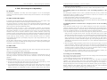
Code
5. Description of Function Codes
Parameter Name
Setting Range
Default
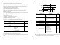
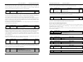
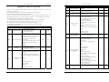
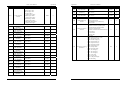
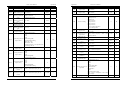
0: 0 decimal display
Number of decimal
1: 1 decimal display
b9-06
places for load
1
2: 2 decimal display
speed display
3: 3 decimal display
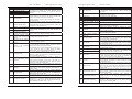
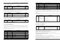
b9-06 is used to set the number of decimal places for load speed display. The following gives an example to
explain how to calculate the load speed:
Assume that b9-05 (Load speed display coefficient) is 2.000 and b9-06 is 2 (2 decimal places). When the
running frequency of the frequency inverter is 40.00 Hz, the load speed is 40.00 x 2.000 = 80.00 (display of
2 decimal places).
If the frequency inverter is in the stop state, the load speed is the speed corresponding to the set frequency,
namely, "setting load speed". If the set frequency is 50.00 Hz, the load speed in the stop state is 50.00 x
2.000 = 100.00 (display of 2 decimal places).
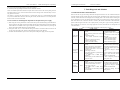
Code
Parameter Name
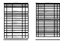
Heatsink
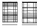
b9-07
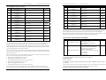
0.0°C ~100.0°C
temperature
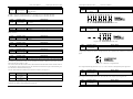
It is used to display the temperature of heatsink.
Setting Range
Default
0°C
Different inverter model has different temperature value for over-temperature protection.
Code
Parameter Name
Setting Range
Default
Accumulative
b9-08
0~65535 h
0h
power-on time
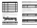
It is used to display the accumulative power-on time of the frequency inverter since the delivery. If the time
reaches the set power-on time (b2-21), the terminal with the digital output function 24 becomes ON.
Code
Parameter Name
Setting Range
Default
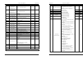
Accumulative
b9-09
0~65535 h
0h
running time
It is used to display the accumulative running time of the frequency inverter. After the accumulative running
time reaches the value set in b2-21, the terminal with the digital output function 12 becomes ON.
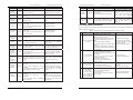
Code
Parameter Name
Setting Range
Accumulative power
b9-10
0~65535 kWh
consumption
It is used to display the accumulative power consumption of the frequency inverter until now.
Default
0 kWh
5.11 Group bA: Communication parameters
Code
Parameter Name
Setting Range
Default
Communication
bA-00
0: Modbus protocol
0
type selection
The EM11 now supports Modbus, later will add the communication protocol such as PROFIBUS-DP and
CANopen. For details, see the description of “EM11 communication protocol”.
5. Description of Function Codes
Code
Parameter Name
Code
Parameter Name
EM11 User’s Manual
Setting Range
Default
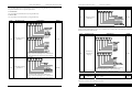
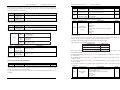
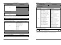
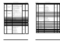
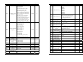
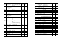
Unit's digit: Modbus baud ratio.
0: 300 BPS
1: 600 BPS
2: 1200 BPS
bA-01
Baud ratio setting
3: 2400 BPS
5
4: 4800 BPS
5: 9600 BPS
6: 19200 BPS
7: 38400 BPS
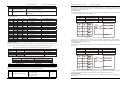
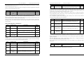
This parameter is used to set the data transfer baud rate from host computer to frequency inverter. Please
note that baud rate of the host computer and the inverter should be consistent. Otherwise, the communication
is impossible. The higher the baud rate is, the faster the communication is.
Setting Range
Default
0: No check, data format <8,N,2>
1: Even parity check, data format<8,E,1>
bA-02 Modbus Data format 2: Odd Parity check, data format<8,O,1>
0
3: No check, data format <8,N,1>
Valid for Modbus
The host computer and inverter setup data format must be consistent, otherwise, communication is
impossible.
Code
bA-03
Parameter Name
Setting Range
Default
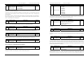
1~249 (0: Broadcast address) Valid for Modbus
Broadcast address
0
When the local address is set to 0, that is, broadcast address, it can realize the broadcast function of host
computer.
The address is unique; it is base of point to point communication between host computer and frequency
inverter.
Code
Parameter Name
Setting Range
Default
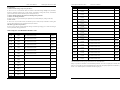
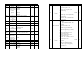
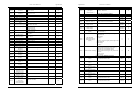
Modbus response
bA-04
0~20 ms (Only valid for Modbus)
2 ms
delay
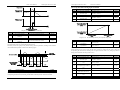
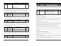
Response delay: it refers to the interval time from the inverter finishes receiving data to response data back
to the host machine. If the response delay is less than the system processing time, then the response time is
based on the time of the system processing. If the response delaying time is more than the system processing
time, after the system processes the data, it should be delayed to wait until the response delay time is reached,
and then sending back data to host machine.
Code
Parameter Name
Setting Range
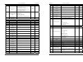
0.0s:invalid
Communication
bA-05
0.1s~60.0s
timeout
Valid for Modbus
When this parameter is set to 0.0s, the communication interface timeout function is invalid.
Default
0.0s
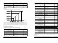
When the function code is set to a value, if the interval time between this communication and the next
communication is beyond the communication timeout, the system will report communication failure error
79
80