1
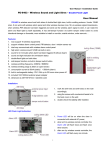
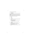
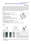
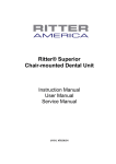
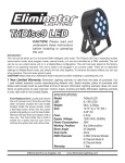
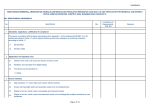
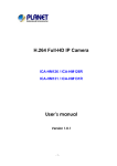
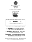
User Manual / Installation Guide
AW-7204P – Wireless PIR Ceiling Mounting Detector / Pet Immunity
User Manual
AW-7204P is wireless PIR ceiling type intrusion detector with pet immunity, it adopts PIR technology intruder
detector designed to detect human body temperature in a protected area, digital processing ensure a high
immunity to false alarms and outstanding stability, it uses a sophisticated radio communication protocol with a high
level of data safety, the detector make auto testing and report its status to the system for full supervision regularly,
built-in tamper switch trigger alarm if there is any attempt to tamper with the detector, auto testing mode make
testing in ease, send out low battery signal indication to alarm panel, hiding ceiling installation.
Features:
1. adopts self-designed MASK chip with DMT technology
2. anti-white light with spherical lens and sealed optical design
3. reliable detection performance with passive PIR technology
4. wireless detect distance: 6 x 6m@0℃ / detection angle: 360°
5. wireless emitting distance is 120 ~ 150 meter (in open area)
6. pet immunity under 25kgs
7. wireless emitting frequency is 433MHz / 868MHz
8. working voltage is 3.0V DC (2pcs 1.5V LR6 Alkaline Battery)
9. Anti-EMI >30V/m(30MHz~1GHz) / Anti-White Light >8000LUX
10. installation height 2.4 ~ 4.8 meter (8 ~ 16 feet) / ceiling installation
11. consumption current is 9uA(static) / 20mA(alarm)
12. alarm indication is LED light flash for 2 seconds
13. operation temperature is -10℃ to +50℃ (14°F to 122°F)
14. storage temperature is -20℃ to +60℃ (-4°F to 140°F)
15. dimension is Φ110*40mm / ivory white color
top view
Installation:
Don’t face cold or
Don’t face the
Don’t install near
Don’t install on a
Don’t face the
hear source
sunshine directly
electric cables
unstable base
metal wall
1. press the bottom of detector, and then clockwise rotation (arrowhead
direction), so that open and take off the ceiling bracket;
2. install 2.4 ~ 4.8m height from the ground;
3. mark the drill hole and drill holes on the ceiling accordingly;
drill hole
install bracket on the ceiling
4. using the screws with countersink heads, so that fix the bracket on the
ceiling;
5. fix the detector back to ceiling bracket (counter-clockwise direction)
after installed the battery;
6. double check the stability after installed.
1
User Manual / Installation Guide
DIP Switch Function:
DIP Switch 1 & 2 setting
1. choose 3 different pulse counting as below:
corresponding working modes:
1-Pulse: detector make the alarm when detected 1 pulse
2-Pulse: detector make the alarm when detected 2 pulse
3-Pulse: detector make the alarm when detected 3 pulse
more pulse counting, the lower performance for sensitivity of capture, but
more pulse counts can reduce fales alarms.
2. setting 3 different working modes as below:
Testing Mode: sending the wireless alarm signal when detector had
DIP Switch 3 & 4 setting
been triggered, no time interval between two signal sending.
Normal/Saving Mode: every 2.5mins detect one time, every 65mins
corresponding working modes:
sending one wireless monitoring signal to report the status of detector and
battery.
Coding Mode: when detector is on working status, inverse it to send an
address code to alarm control panel
side view
top view
Inside Diagram:
DIP switching
tamper
Note:
switch button
turn on tamper function, only cover one
PIN;
turn off tamper function, cover 2 PINs
together.
tamper function
battery tray
switch - PIN
Coding Method:
(between detector and wireless alarm panel)
1. detector on normal mode, place the alkaline battery and LED light will flash few seconds; alarm control panel
on wireless coding mode (please refer alarm control panel user manual), press tamper switch to sending the
wireless signal to alarm control panel, if alarm control panel make the corresponding indicate sound, it means
match code successfully.
2. alarm control panel on manual coding mode, enter the 9 digit address code to match,
this will be a higher probability of coding success.
mounting holes
9 digit address code
2
User Manual / Installation Guide
Change Battery:
when detector sending the wireless signal, LED light flash, it means the low battery
situation, and detector also can sending the low battery alarm indication to alarm
control panel.
(2pcs 1.5V LR6 Alkaline Battery / pay attention to the anode and cathode)
battery tray
Walk Testing on Cover Area:
1. detector on testing mode, pulse counting set as 1, 2 or 3-Pulse;
2. horizontal movement which triggers detector alarming at the remote of the detection coverage at the speed of
0.75m/s, the LED light indicator will flash few seconds;
3. testing in different direction to confirm the two boundaries of the coverage, ensure the detector is appointed to
the central desired area;
4. the centre of detection area should not be towards vertical incline, if can not obtain an ideal detection area,
please adjust the vertical angle to ensure direction for detector neither high or low;
5. once detection angle is adjusted, walk testing must
be performed again;
6. please set detector to normal mode after finished
walk testing.
Warning: we are not responsible for the problem caused by improper operation or change the product
configuration, it may lose the authority of product warranty!
3