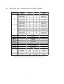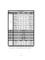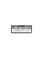
1
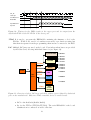
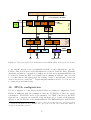
LHCb 2003-007
IPHE 2003-02
February 17, 2003
Common L1 read out board for LHCb
specification
Aurelio Bay a 1 , Jorgen Christiansen b 2 , Guido Haefeli a 3 ,
Federica Legger a, Laurent Locatelli a, Ulrich Uwer c 4 ,Dirk
Wiedner c 5 .
a Institut de Physique des Hautes Energies, Université de Lausanne
b Cern, Geneva
c Kirchhoff-Institut für Physik, University Heidelberg
Abstract
This document specifies the the L1 readout board used by several sub detectors of
LHCb. It specifies the interface to the sub-detector specific receiver cards and all the
common interfaces for the LHCb environment.
1
E-mail:
E-mail:
3
E-mail:
4
E-mail:
5
E-mail:
2
[email protected]
[email protected]
[email protected]
[email protected]
[email protected]
Contents
1 Introduction
1
2 Shortcuts
2
3 Requirements
2
4 L1 data flow architecture
4.1 L1 buffer . . . . . . . . . . . . . . . . . . . . . . . . . . . . . . . . . . .
4.2 DAQ readout . . . . . . . . . . . . . . . . . . . . . . . . . . . . . . . .
3
4
5
5 A-RxCard and O-RxCard
5.1 ECS access . . . . . . . . . . . . . . . . . . . . . . . . . . . . . . . . .
8
8
6 PP-FPGA
6.1 I/O count . . . . . . . . . . . . . . . . . . . . . . . . . . . . . . . . . .
8
9
7 Data synchronization and event synchronization
7.1 Data synchronization for the Velo . . . . . . . . .
7.2 Data synchronization for the O-RxCards . . . . .
7.3 Event synchronization for the Velo . . . . . . . .
7.4 Event synchronization for OT . . . . . . . . . . .
.
.
.
.
.
.
.
.
.
.
.
.
.
.
.
.
.
.
.
.
.
.
.
.
.
.
.
.
11
11
11
11
11
8 SyncLink-FPGA
8.1 32-bit L1T fragment link . . . . . . . . . . . . . . . . . . . .
8.2 16-bit DAQ fragment link . . . . . . . . . . . . . . . . . . .
8.3 VeLo cluster formats for fragment links . . . . . . . . . . . .
8.4 Conversion of Strip number to physical position for the Velo
8.5 Outer Tracker cluster format for fragment links . . . . . . .
.
.
.
.
.
.
.
.
.
.
.
.
.
.
.
.
.
.
.
.
.
.
.
.
.
.
.
.
.
.
12
13
15
15
16
16
.
.
.
.
.
.
.
.
.
.
.
.
.
.
.
.
.
.
.
.
9 TTCrx interface
17
10 FEM for Beetle based read out
18
11 ECS interface
11.1 PLX parallel local bus . . . . . . . . . . . . . . . . . . . . . . . . . . .
18
20
12 FPGA technology
12.1 Altera . . . . . . . . . . . . . . . . . . . . . . . . . . . . . . . . . . . .
12.2 Xilinx VirtexII . . . . . . . . . . . . . . . . . . . . . . . . . . . . . . .
12.3 Device choice . . . . . . . . . . . . . . . . . . . . . . . . . . . . . . . .
21
21
22
22
13 L1 trigger and DAQ interface - RO-Tx
13.1 Gigabit Ethernet . . . . . . . . . . . . . . . . . . . . . . . . . . . . . .
13.2 Implementation of a dual Gigabit Ethernet on the board . . . . . . . .
13.3 Upgrade interface . . . . . . . . . . . . . . . . . . . . . . . . . . . . . .
23
23
23
24
14 Resets
24
i
15 Clock distribution and signal termination on the board
24
16 FPGA configuration
25
17 JTAG boundary scan
26
18 Power requirements
26
19 Physical aspects of the ROB
27
20 FPGA implementation guidelines
27
21 Open questions
28
A I/O Tables
31
B Register and local parallel bus address space definition
33
C I2C address definition
36
D Signal tables
37
E Pin out for connectors on the board
41
ii
1
Introduction
Several sub-detectors of LHCb as Velo,ST,TT,Veto and OT have decided to use a very
similar read out schemes for their detectors. In order to minimize the amount of (L1)
electronics in the radiation area, the LO accepted data is transmitted directly over
long analog copper (in case of the Velo) or digital optical links (for all the other subdetectors) to the counting room. With the use of the same read out chip for Velo, ST
and TT, the development of a common L1 electronics read out board has been started
already in the early design phase. Due to the circumstance of having two different link
implementations, the L1 electronics read out board (L1-ROB) has been designed to be
adaptable for the two link system. In case of the Velo, the receiver side digitizes the
analog signals and for the optical links, the data serialized with the GOL chip close to
the detector is de-serialized with the TLK2501 SERDES from Texas Instruments. Lack
of choice, several other sub-detectors do also foresee the GOL-TLK2501 transmission
leading to an identical hardware interface to the L1-ROB. For synchronization, L1
buffering, L1T zero suppression and DAQ zero suppression several large FPGAs are
placed on the motherboard. This allows the adaption of the board to the special needs
of processing the data. Also some parts of the FPGA firmware has to be developed
specific to the sub-detectors, a common framework including all interfaces can be used
by all user of the board.
1
2
Shortcuts
A-RxCard
Analog Receiver Card
O-RxCard
Optical Receiver Card
RxCard
Receiver Card (stands for A-RxCard and O-RxCard)
PP-FPGA
Pre Processor FPGA
SyncLink-FPGA
Synchronization and Link FPGA
ROB
Read Out Board
FEM
Front End Emulator
L1B
L1 Buffer
L1T
L1 Trigger
L1A
L1 Accept
DAQ
Data Acquisition
TTCrx
TTC receiver chip
ECS
Experimental Control System
TLK2501
Texas Instruments SERDES chip
GOL
Cern implementation of a radiation hard 1.6-Gbit/s serializer
RO-TxCard
Read Out Transmitter Card
DDR SDRAM
Double Data Rate Synchronous Dynamic RAM
SERDES
Serializer and de-serializer circuit
L1T ZSupp
L1 trigger zero suppression
OSI
Open Systems Interconnect Model
MAC
Medium Access Controller, Gigabit Ethernet terminology
PHY
Physical layer device, Gigabit Ethernet terminology
POS PHY Level 3 Saturn compatible Packet Over Sonet interface level 3 used
for 1 Gigabit Ethernet
POS PHY Level 4 Saturn compatible Packet Over Sonet interface level 4 used
for 10 Gigabit Ethernet
GMII
Gigabit Medium Independent Interface, 8-bit parallel PHY
interface
3
Requirements
The L1 ROB is used by several sub-detectors in LHCb. Special requirements are
given by different sub-detectors concerning interconnection and synchronization. In
most aspects the Velo imposes the strongest requirements and is therefore taken to
guide the implementation. In the following list, important aspects for the various subdetectors are summarized to give a general overview of the most demanding aspects of
each sub-detector:
• Velo
– The L1 electronics interface is analog and digitization must be done on the
receiver part (A-RxCard).
2
– The number of input data and clocks signals is higher than for other subdetectors since the receiver card is working as digitizer and the data is sent
out to the motherboard at 40M Hz on 32-bit wide buses.
– The Velo must provide the information to the L1 trigger.
– An advanced common mode suppression algorithm is foreseen to be implemented for the L1 trigger pre processor and the DAQ interface.
– The synchronization of the sampled data needs a local front end emulator
to generate a data valid signal.
• ST,TT
– The data is sent multiplexed on 16+2-bit wide buses at 80M Hz from the
optical receiver card (O-RxCard) to the motherboard. The higher frequency
and fast signal edges of these signals need to be taken into account.
– With 24 optical links on the ROB, the L1B needs to be designed for this
data stream which is higher than for the Velo.
– TT must provide information to the L1 trigger.
• OT
– The high occupancy on this detector imposes a high bandwidth for the whole
readout path.
4
L1 data flow architecture
In figure 1 a block diagram of the ROB is given to show its partitioning in different
daughter cards and FPGAs. Four or two independent receiver mezzanine cards (ARxCard or O-RxCard)6 can be plugged onto the motherboard. The receiver card is
directly connected to the PP-FPGA which is the main processing unit on the board.
Each PP-FPGA uses several independent L1B and L1B controller to store the data
during the L1 latency. After zero suppression for the L1T and the DAQ, the data
is linked and encapsulated on the SyncLink-FPGA. The same FPGA is also used to
process the TTCrx, ECS and FE emulator information to issue resets, synchronize the
PP-FPGA processing, and distribute clocks and L1T decisions. The data is sent to
the event building network via the read out transmitter (RO-Tx). A more detailed
representation of the whole ROB is given in figure 2 for the Velo and in figure 3 for
the optical read out. To reduce the number of I/O pins used on the PP-FPGA, the
data from two synchronization channels are sent to one L1B controller using the full
bandwidth of a 16-bit double data rate SDRAM running at 120M Hz. The event rate
of 40kHz at the DAQ zero suppression allows to use a single common mode and zero
suppression for all data on one chip. The slow control of the FPGAs is done with a
8-bit wide address and data multiplexed parallel interface. This interface is generated
from the PCI bridge on the Glue Card and is called the ”Local Bus” of the PLX9030.
The ECS interface allows to access the local 32-bit memory space containing registers,
6
Two receiver card types are foreseen, one for the Velo analog electrical readout and the other for
the optical readout.
3
FE
FE
FE
FE
A-RxCard
(O-RxCard)
A-RxCard
(O-RxCard)
A-RxCard
(O-RxCard)
A-RxCard
(O-RxCard)
PP-FPGA
PP-FPGA
PP-FPGA
PP-FPGA
L1B
L1B
L1B
L1B
SyncLink-FPGA
ECS
ECS
FEM
RO-Tx
TTCrx
TTC
L1T
DAQ
L1 throttle
Figure 1: An overview of the building blocks on the L1 ROB.
constant tables and the L1 buffers. The TTCrx, A-RxCard and the FEM are connected
to individual I 2 C buses for direct ECS access.
4.1
L1 buffer
A block diagram of the principle of the L1 buffer controller is shown in figure 4. The
data coming from two synchronization channels are written to the L1B by one L1B
controller. Its Arbiter allows to schedule the required transaction. It checks on the
state of the InFifo (indicated with the UsedWords signal) and performs the read out
of the L1 accepted events only if the InFifo does not risk to overflow. A possible
sequence can be seen in figure 5. With a clock frequency of 120M Hz 7 enough cycles
are available for arbitration and refreshing. In table 1 the necessary cycle count for
each task on the SDRAM is given. The chosen SDRAM frequency leads to a sufficient
high bandwidth of the memory and allows to keep the InFifos small (about 4 events)[2]
8
.
7
8
With a clock frequency 120M Hz the data transfer rate is at 240M Hz.
The simulation for the L1B access with this scheme has to be verified by simulation.
4
16 Analog
Electrical link
from
FE
X4
A-RxCard (Mezzanine card)
DDR
@120MHz
16-bit data
13-bit addr
32
32
Sync
32
Sync
Sync
X4
@40MHz
32
Sync
16
L1B
L1B Ctrl
16
L1B
Clk
Gen
L1B Ctrl
16
L1B Ctrl
32
32
Analyzer
IF
32
32
32
32
L1T
ZSupp
L1T
ZSupp
L1T
ZSupp
L1T
ZSupp
8
8
8
8
@80MHz
@80MHz
DAQ PPLink
8
L1T PPLink
DAQ
ZSupp
8
1
6
To and from all 4 PP-FPGA
From all 4 PP-FPGA
Data
@80MHz
16
Analyzer
IF
PP- FPGA
@120MHz
To PP-FPGA
left and right
L1A
GEN
Broad
Cast
Throttle
32
FEM
Sync
DAQ and L1T Link
32
TTCrx
TTC
Data
@80MHz
DataValid
RO-Tx
Throttle
SyncLink-FPGA
L1B
Sync
PP
L0Accept
FEM
To event building network
Figure 2: Data flow of the ROB for the Velo read out. Only one A-RxC and PP-FPGA
is shown. The FIFO data buffers on the in and output of the logic blocks are indicated
as small dark rectangles.
4.2
DAQ readout
The readout starts with the L1T decision distributed over the TTC broadcast command
which is interpreted on the SyncLink-FPGA. Over a serial link, the EvCnt and trigger
5
6 single
or
1/2 12 way
optical fibers from
FE
DDR
@120MHz
16-bit data
13-bit addr
X2 or X4
O-RxCard (Mezzanine card)
@80MHz 16
16
Sync
16
Sync
16
Sync
16
Sync
X4
16
Sync
Sync
16
L1B
@40MHz
L1B Ctrl
16
L1B
L1B Ctrl
16
L1B
L1B Ctrl
32
32
32
32
32
32
L1T
ZSupp
L1T
ZSupp
L1T
ZSupp
L1T
ZSupp
L1T
ZSupp
L1T
ZSupp
8
8
8
8
8
8
32
32
32
Analyzer
IF
@80MHz
DAQ PPLink
8
L1T PPLink
DAQ
ZSupp
8
1
6
To and from all 4 PP-FPGA
From all 4 PP-FPGA
Data
@80MHz
16
Analyzer
IF
L1A
GEN
Broad
Cast
Throttle
Data
@80MHz
32
DAQ and L1T Link
SyncLink-FPGA
@80MHz
PP- FPGA
@120MHz
To PP-FPGA
left and right
32
TTCrx
TTC
RO-Tx
Throttle
To event building network
Figure 3: Data flow of the ROB for the optical read out. The diagram shows the data
flow for 6 optical links and the linking on the board.
type is transmitted to the PP-FPGA. The Arbiter reads the requested events stored at
the start address given by the EvCnt. With the EvCnt also stored in the event header
the correct operation can be checked for each event. The events are collected in the
DAQ-PPLink and zero suppressed in DAQ-ZSupp. The data from all PP-FPGAs on
6
From RxCard
Data
DDR
SDRAM
CTRL
@120MHz
(IP CORE)
RdData
2x16-bit@ 120MHz
Addr
WrData
16
InFifo
InFifo
RdReq
Select
WrEvCnt
WrEvCnt
RdReq
WrReq
32
32-bit @ 40MHz
L1T
ZSupp
RdAddr
Sync
InFifo
16
WrAddr
32
UsedWords
13
Sync
InFifo
MUX
16
256-Mbit
DDR
SDRAM
2x16-bit@ 120MHz
L1B controller
L1T
ZSupp
To L1T PPLINK
Arbiter
32
RdEvCnt
Data to DAQ_PPLink
From SyncLink_FPGA Rd/Wr access
for ECS
Figure 4: Detailed L1B controller block diagram.
Rate
Task
Cycle count
Each event
Write CH0
2.5+34
Each event
Every 2 events
Every 2 events
Every 25 events
Every 25 events
Every 8 events
Write CH1
Active
Precharge
Read CH0
Read CH1
Refresh
34
3
3
6+2.5+34
34
10
Cyles available
Average Cycle
108 per event
78 per event
Remark
Data transfer is 2 word per cycle
Performed after CH0 writing
Activate the row (open)
Deactivate the row (close)
Performed after CH0 reading
Refresh once per 7.8µs
900ns/8.3ns
72%
Table 1: SDRAM cycle access statistic.
Write
CH0 CH1
CH0 CH1
Read
CH0 CH1 CH0 CH1 CH0 CH1
CH0 CH1
Refresh
R
0
1
2
3
4
5 time [900ns]
Figure 5: Example how the Arbiter schedules the required transactions.
7
the board are linked and encapsulated on the SyncLink-FPGA to be finally sent to
the RO-Tx. To unload the task of the PP-FPGA and its need of resources, the DAQ
zero suppression can optionally also be performed on the SyncLink-FPGA. Doing so,
all raw data from the whole ROB can be linked before being zero suppressed.
5
A-RxCard and O-RxCard
At present, two different receiver daughter card implementations are foreseen to be
plugged on the motherboard. This is necessary due to the different data transmission
system from the cavern to the counting room. For the Velo, the receiver card is used
to digitize the data transferred over analog copper links [6] and therefore is a mainly
analog circuit with pre-amplifier, line-equalizer and ADC. This card is called A-RxCard.
The optical receiver card is used by all other sub-detectors as IT, TT and OT. It uses
optical receiver and de-serializer which results in a mainly digital design except for the
optical receiver part. This card is called O-RxCard. The signal connection from the
receiver cards to the motherboard is split up into 4 separate connectors. The physical
placement is chosen such that 2 or 4 mezzanine cards can be inserted, giving flexibility
for the receiver card design. Table 18 shows the number of digital signals on the signal
connector for different implementations. The connector chosen provide massive copper
plate for GND and Vcc connection and ensures very good signal integrity properties 9 .
The motherboard is designed to allow 64 analog links digitized with 8 or 10-bit 10 for
the A-RxCard. The number of pins needed for the RxCard is driven by the A-RxCard.
In addition to the signal connectors, analog power connectors are used to supply the
RxCard with all necessary analog power (see table 19). All control signals for the
O-RxCard are assigned to pins of the not used data signals ( 160 data signals are used
for the Velo and only 108 for the O-RxCard) which minimizes the number of required
pins on the connecter.
5.1
ECS access
I 2 C is used for the slow control the RxCard. The four cards share the address space
of one dedicated I 2 C bus where the two highest address bits (bit 6 and 7) are defined
on the motherboard (see table in appendix 17). All other bits have to be set on the
receiver cards.
6
PP-FPGA
With a long list of tasks this FPGA demands for a high amount of resources. Detailed
studies for the implementation of the zero suppression for the the L1T called L1PPI
have been done in [1] to estimate the amount of logic gates and memory needed on
the PP-FPGA. In table 2 an overview of the estimated resources is given for the
9
For the digital signal connectors a 200 pin, 0.643mm pitch connector has been chosen (see.
http://www.samtec.com/ftppub/pdf/QTS.PDF and
http://www.samtec.com/ftppub/pdf/QSS.PDF
10
Using a 10-bit ADC is optional for the A-RxCard and therefore it needs to be supported by the
ROB. The further processing will be done on 8-bit resolution.
8
implementation of the LCMS algorithm also described in [1]. The implementation
has been optimized for the Altera APEX20K FPGA architecture but also allows to
estimate the resources used in an other FPGA. Using the Altera Stratix FPGA devices
allows to implement the MAC (multiply accumulation) operations with the embedded
DSP blocks. This reduces significantly the LEs (logic elements) used for the design.
Functional block
Logic
Elements
(LE)
Block
memory
512 bit
Block
memory
4k
Block
memory
4k x 144
DSP
blocks
PLL
L1 trigger ZSupp
⊕DAQ ZSupp
L1B
Synchronization
ADC clock gen.
Total
6000
3000
3000
1000
200
13200
60
20
0
0
0
80
8
12
12
12
0
44
0
0
0
0
0
0
60
20
0
0
0
80
1
0
1
0
2
4
Available in 1S20
18460
194
82
2
80
6
Available in 1S25
25660
224
138
2
80
6
This is the estimated number with the assumption that the processing is done
with 160M Hz.
⊕ The zero suppression can also be done on the SyncLink-FPGA, which reduces the
resources needed on the PP-FPGA.
Table 2: Estimation of needed resources on the PP-FPGA. For sub-detectors not contributing to the L1 trigger, the logic resources on the chip are available for other tasks.
6.1
I/O count
To determine the package size of the FPGA a detailed count of the I/O is listed in
table 10. The number of data signals plus the I/O pins used for reference voltage of
the SSTL-2 and the reference impedance for the source termination are also included
in this calculation. The calculated number of I/O is supported by several packages and
devices of the Altera Stratix FPGAs. To allow the migration between different devices
the necessary number of I/O has to be available by all desired devices.
9
Altera
Stratix
(Cyclone)
Device
400-Pin
FineLine
BGA
EP1S10
EP1S20
EP1S25
EP1S30
EP1C20
672-Pin
FineLine
BGA
780-Pin
FineLine
BGA
Comment
341
422
469
422
582
593
593
not enough I/O
301
biggest Cyclone device
Table 3: The 780-pin FBGA package allows to migrate between several devices.
10
7
Data synchronization and event synchronization
For a better understanding of the synchronization mechanism on the board it is useful to distinguished between data and event synchronization. In this context data
synchronization comprises the generation of the sampling clock of the ADC for the
A-RxCard, selecting the valid data out of the continuous sampled analog signals and
changing the clock domain on the input stage of the FPGA to the on chip common
clock domain. For the optical receiver card the data synchronization is given by the
interface of the deserializer. The event synchronization is a second step and performs
consistency checks between the transmitted event identification in the header and the
local reference. This separation can be understood as a two layer transmission model
where the data synchronization is on the Physical layer and the event synchronization
is the DataLink layer of the OSI model.
7.1
Data synchronization for the Velo
The analog signal transmission over 40m twisted pair copper links suffer from a skew
among channels on the same cable of order 5ns which has to be compensated by using
channel individual phase adjustable clocks for sampling the signals. These clocks are
generated using the PLL circuits on the PP-FPGAs. The details of its implementation
are given in [3]. The data valid signal available on the Velo FE-chip (Beetle) is not
transmitted to the read out electronics over the analog links. The principle to select
the valid data from the continuous sampled signals is based on the data valid signal
regenerated by the local FEM. The data has further to be synchronized to the common
40M Hz clock domain which is done by the use of FIFOs on the input stage. The
synchronization is illustrated in figure 6.
7.2
Data synchronization for the O-RxCards
The TLK2501 SERDES chip used on the O-RxCards is generating the clock, data
enable and an error signal which are used to synchronize the data on the input of the
PP-FPGA. The multiplexed data is de-multiplexed and written to an input FIFO to
allow the change of clock domain for the following processing stages. The independent
synchronization of each optical input link makes the skew between the optical channels
not an issue.
7.3
Event synchronization for the Velo
After the valid data is masked, the header words representing the pipeline column
number (8-bit PCN) can be verified. This is done among the neighboring channels and
the reference from the FEM.
7.4
Event synchronization for OT
The data headers from the OTIS TDCs (??) include a 8-bit BCnt that will be compared
to the BCnt generated on the board. On error the BCntError bit will be set. The
BCnt will be used together with the TDC ID to do the de-serialization from 80M Hz
11
FIFO
DC
ADC_clk
Clk_40
Data
WR
Wr_req
Data
Check: PCN
ADD:BCnt,EvCnt
Rd_req
I2C
SyncEvCntStr
SyncBCntStr
SyncPCNStr
Clk_40
SyncData<5:0>
Valid
Delay
SyncDataValid
Sync
Data
RD
ZSupp
Analog input data
ADC
8(10)-bit
PP-FPGA
Clk_40
Clk Generator
Reset
I2C
L0Accept
FEM
(Beetle)
Clk_40
EvSync
Data<3:0>
TTCrx
interface
TTCrx
DataValid
SyncLink-FPGA
Figure 6: ADC input data synchronization for the Velo.
to 40M Hz. After error checking and verification of the correct data header for each
Otis, the EvCnt and BCnt will be added to the data and stored in the L1B.
8
SyncLink-FPGA
Cluster A cluster is formed when one or multiple neighboring detector channel carry
a signal. The proposed cluster size for the L1T is one 16-bit word. The cluster
size for the DAQ is variable depending on the number of hits in the cluster but
is transmitted in 16-bit words.
Event fragment All clusters for one event on one PP-FPGA is called an event fragment.
This FPGA is used to distribute control signals, interfacing the TTCrx and the FEM,
linking the cluster fragments from the whole board and sending the data to the RO-Tx.
The cluster collection uses FIFO based interfaces from the PP-FPGAs to the SyncLinkFPGA. The FIFOs are either located on the input stage of the SyncLink-FPGA as a
baseline or optional for sub-detectors using the SyncLink-FPGA for the DAQ zero
suppression, on the PP-FPGA. The links to collect the clusters on the L1T interface
12
Clk
RO-TxClk
ECSClk
Clk_40
Status
LED
Clk_80
Clock
Generator
BrdRst
Broad
Cast
CMD
TTCrxRst
BCnt
L1A
Generator
Clk_40
L0Reset
SyncData
Generator
PCN
Throttle
SyncDataStr
36
Location
Conv RAM
From PP-FPGA’s @80MHz
16
DAQ Link &
Encapsulation
F
I
F
O
64
64
32
L1T Link &
Encapsulation
F
I
F
O
Analyzer
IF
EvCntReset,BCntReset
SyncData
6
Throttle
OR
RO-Interface
To RO-Tx
1
L1AStr
@80MHz
FEM
SyncRst
L1EvIDReset
L1Accept
L1A
FIFO
12
Reset
Generator
FIFO
TTCrx
To PP-FPGA’s
Brcst
32
10
SyncLink-FPGA
Figure 7: Data flow overview of the SyncLink-FPGA
are chosen 32-bit wide for the L1T and 16-bit for the DAQ. The functionality foreseen
at the present to be implemented for the Velo,ST/TT and OT does not demand a high
amount of logic resources on this FPGA. An estimation is given in table 4.
8.1
32-bit L1T fragment link
With a transfer rate of 80M Hz and a cluster size of 16-bit, the data transfer is restricted
to 128 clusters plus the header each event, leaving a margin of 10 cycles for start and
13
Functional block
Logic Elements
(LE)
Block
memory
512 bit
Block
memory
4k
Block
memory
4k x 144
DSP
blocks
PLL
L1T fragment link
L1T location conversion
DAQ fragment link
Control generators
RO-Tx interface
Total
1000
0
1000
2000
1000
5000
0
0
0
0
0
0
8
8
8
8
8
40
0
0
0
0
0
0
0
0
0
0
0
0
1
0
0
2
1
4
Available in 1S20
18460
194
82
2
80
6
Table 4: Estimation of needed resources on the SyncLink-FPGA.
stop the transfer 11 . Additional hits or clusters need to be discarded to allow the linking
to be performed with a fixed latency of 900ns. Fixing the event linking latency prevents
from possible buffer overflows at the FIFO buffers. The fragments with discarded
clusters are flagged as such in the ErrorFlag word. If a higher bandwidth on these links
is needed, the clock frequency can be increased up to 160M Hz without any changes
on the link hardware 12 . The increase of the bandwidth on the board is general less
critical then the link bandwidth to the L1T event building network. To transmit 128
16-bit clusters / event needs a minimal bandwidth of 4-Gbit/s.
Velo To find the most appropriate cluster encoding schema the distribution for 1, 2 or
multiple hit clusters has been simulated and the most appropriate data model has
been discussed [4]. With an expected occupancy of order 0.6% or an average of
15 clusters/board/event [8]the most reasonable cluster encoding is the following:
• One hit clusters are marked as of size 1 and its strip number is transmitted.
• Two hit clusters are marked as size 2 and the strip number of only the first
strip is transmitted.
• Clusters with three and more hits are split up into clusters of size one and
two.
To allow a flexible limitation of the readout data, the maximal number of clusters
sent to the L1T can be limited at the two linking stages. The limits can be set
per PP-FPGA and for the whole ROB on the SyncLink-FPGA.
ST/TT As for the Velo.
OT With 6 optical links per PP-FPGA, a total of 1536 channels are processed on
the ROB. The restriction to 128 hits/event per PP-FPGA allows to read out a
maximal local occupancy of 33%. With a zero suppression that allows to encode
11
Available cycles: 900ns/12.5ns=76, Cycles not used: 76-2-128/2=10
The point to point links are terminated with serial resisters on the source side which is implemented
in the FPGA I/O structure. The perfect termination allows to run at high frequencies.
12
14
multiple hits in one cluster a significant data reduction can be obtained. With
the assumption that only binary information per hit needs to be sent to the L1T,
the non zero suppressed information on the fragment link is 384-bit or 24 16-bit
words, which is equal to an occupancy with single hit encoding of 6.25%. This
value is an upper limit to the necessary bandwidth .
8.2
16-bit DAQ fragment link
To link and transfer the DAQ fragments an average time of 25µs is allowed 13 . The
16-bit wide links permit to transfer the event fragments without the need of deep FIFO
buffers. Also the bandwidth allows to transfer very long fragments, a restriction on the
length of the fragments can help to avoid overflows and is foreseen to be implemented
as a value to be set on the FPGA. In figure 8 the event fragment format is given for
both links.
DAQFragmentFormat,16
L1TFragmentFormat,32
R,4
R,4
BCnt, 12
Cluster(2), 16
Cluster(4), 16
Cluster(6), 16
ErrorFlag, 8
N, 8
EvCnt, 16
Cluster(1), 16
Cluster(3), 16
Cluster(5), 16
Unused or Cluster(N), 16
TriggType, 4
EvCnt(3:0),4
DataLength DL, 12
BCnt, 12
EvCnt(23:4), 16
ErrorFlag, 8
PCN, 8
ClusterHeader(1,1),16
ClusterData(1,2), 16
ClusterData(1,3), 16
N
Cluster(N), 16
ClusterData(1,L1), 16
DL
ClusterHeader(N,1), 16
ClusterData(N,LN), 16
Figure 8: Link format for L1T and DAQ between PP-FPGA and SyncLink-FPGA.
8.3
VeLo cluster formats for fragment links
The L1T cluster in case of the Velo has the following format: The DAQ event fragment
Bit
0
< 12 : 1 >
13
< 15 : 14 >
Description
Cluster size Is 0 for clusters of one hit and 1 for two
hits
Strip number Unique strip number on the ROB
Second threshold If one of the hits in the cluster exceeded the second threshold level this bit is set.
Unused
Table 5: Velo cluster format for the L1 trigger.
13
With a L1 accept rate of 40kHz.
15
Comment
do have a more complicated structure. In case for the Velo the following information
is sent to the DAQ wrapped in 16-bit wide words:
Size
4-bit
8-bit
12-bit
Nh x 8-bit
4 x 8-bit
Description
Cluster size Number of data words in the cluster.
L1T information The result of the L1T pre-processor
algorithm for each strip value (hit and second threshold)
NStrip Strip number of the first hit in the cluster.
Strip values Nh is the number of hits in a cluster.
Neighbor strip values The two right and left neighboring strip values to the cluster.
Table 6: Velo cluster format for the DAQ.
8.4
Conversion of Strip number to physical position for the
Velo
Each strip number on the board (11-bit for 2048) has to be converted in a physical
location according to the alignment tables calculated off line and downloaded to the
SyncLink-FPGA. The size of the alignment table of (2k x 12 bit or 32kbit ) which
corresponds to a physical resolution of about 5µm. This table can be implemented
either in 8 x 4kbit memory blocks or in one 512 kbit also available on the SyncLinkFPGA.
8.5
Outer Tracker cluster format for fragment links
In preparation
16
9
TTCrx interface
The TTC receiver chip synchronization signals are connected to the SyncLink-FPGA
(table 21). The distribution of clock, trigger and event synchronization signals is done
with point to point links to each PP-FPGA. The clocks can be individually phase
adjusted to ensure the correct clock phase between the FPGAs on the board. The
configuration registers can be loaded over an ECS driven I 2 C bus. For production
testing the JTAG boundary scan interface is connected to the overall JTAG chain.
The used of a configuration EEPROM is not foreseen and the configuration registers
have to be loaded at each power up. The TTCrx is directly mounted on the board
to reduce cost and board space 14 . For further documentation refer to the TTCrx
user manual [9]. The The following synchronization tasks are implemented on the
SyncLink-FPGA using the TTTrx signals 15 :
TTCrx reset All resets on the board are distributed from the SyncLink-FPGA (see
section Resets).
TTCrx status DbErrStr and SinErrStr are counted with saturated 16 16-bit counters
and are accessible on the ECS registers TTCErrCntReg. TTCReady is accessible
on BoardStatReg.
Clock The Clock40Des1 is used for the board wide 40M Hz clock called clk 40. The
PLL based clock management circuit on the SyncLink-FPGA allows to distribution the system clock to all necessary locations without external clock buffers.
The Clock40 and Clock40Des2 are also connected to the SyncLink-FPGA but
are not used yet.
BCnt The bunch counter is available on the BCnt bus during the BCntStr high,
synchronized to the Clock40Des1 and reset by BCntRes. The bunch counter is
transmitted to the PP-FPGAs via 6-bit wide SyncData bus and therefore has to
be multiplexed during two clock cycles. The timing diagram for the SyncData
and its strobe signal SyncStr is given in 10.
EvCnt The low part (12-bit) of the event counter is available on the BCnt bus during
the EvCntLStr high and the high part during EvCntHStr high. The BCnt signals
are synchronized to the Clock40Des1 and reset by EvCntRes. The event counter
is also transmitted on the SyncData bus over four clock cycles.
Brcst The setting of the TTCrx is made such that the broadcast command data
signals are all synchronous to Clock40Des1, the appropriate settings are made on
the control registers of the TTCrx. The broadcast command is used to decode
the LHCb L1 accepted events (see the broadcast command figure 9).
L1 accept The TTCrx signal called L1accept is named L0acceptLHCb to avoid any
problems with the LHCb naming convention. It is used for the Velo FEM and is
also used to generate the EvCnt independent of the TTC BCnt which allows to
verify the correct synchronization.
14
The chip is packaged in an 144-pin FBGA package (13mm x 13mm)
Signals named Str at the end are strobe signals and are used to latch the corresponding data bus.
16
At overflow the value of the counter remains at 0xffff.
15
17
For the optical receiver the Agilent HFBR-2316T is used, which is recommended for
the use for the TTC system in the counting room 17 .
Trigger type:
0: Reject
1: Physics
2-7: Resvd
LSB of
event ID
L1 trigger
1
Reset
0
1
Resvd
CMD1
(calibration)
0
0
0
1
CMD2 (Resvd)
CMD3 (Resvd)
0
0
0
0
1
1
0
1
L1 event
ID reset
L1 front- L0 frontEvCnt
end
end
reset
reset
reset
Calibration pulse
type:
0: Default
1-3: Resvd
x
x
x
x
BCnt
reset
Figure 9: Broadcast command interpreted by the SyncLink-FPGA defined for LHCb.
10
FEM for Beetle based read out
The FEM used by the sub-detectors with the Beetle FE-chip [10] is controlled with
I 2 C and interfaced to the SyncLink-FPGA. Its task is to generate the DataValid signal
which is not transmitted with the detector data. In addition the the PCN is extracted
to check the synchronization between the FEM and the data from the FE. In addition
the available status signals from the Beetle are also connected to the SyncLink-FPGA
and made available in a register for status monitoring. In table 22 in the appendix,
the signals on the FEM interface are given. The PCN is available on the FEMData
bus and has to be sampled with respect to the FEMDataValid signal as shown in the
timing diagram figure 10. The FEMData bits have to be re-ordered as indicated, the
upper 4 bits are not used. The distribution of the 8-bit PCN to PP-FPGA is done on
the SyncData bus. The strobe signal SyncPCNStr generated is used by the PP-FPGA
to latch the data on the SyncData bus. The PCN is transmitted over the SyncData bus
to the PP-FPGAs and has to be multiplexed on the SyncLink-FPGA. The definition of
the header data bits sent by the Beetle FE chip is given in the specification of that chip.
The PCN is sent over two clock cycles via 6-bit wide bus from the SyncLink-FPGA to
the PP-FPGAs.
11
ECS interface
With the use of the LHCb specific CC-PC and the adaption Glue Card, all necessary
interfaces are provided.
17
http://literature.agilent.com/litweb/pdf/5988-2576EN.pdf
18
Clk_40
L0Accept
PCNa
FemData<3:0>
PCNb
D0
D1
PCN0
PCN1
D2
D3
D4
D5
D6
D7
EvC0
EvC1
EvC2
EvC3
D30
D31
DataValid
SyncData<5:0>
BCnt0 BCnt1
SyncStr
Figure 10: Timing for the FEM signals in the upper part and its output from the
SyncLink-FPGA to the PP-FPGA in the lower part.
JTAG It is used to program the EEPROM containing the firmware code for the
FPGAs. JTAG is also used for boundary scan used for production testing but
this chain is separate from the programming chain and not connected to the ECS.
I2C Multiple I2C buses are used on the board. Four independent buses are provided
by the Glue Card, allowing individual buses for (see figure 11):
SyncLink-FPGA
PP-FPGA
FPGAI2C
RxI2C
CC-PC
PCI
FEMI2C
Glue
Card
RxCard
b”00xxxxx”
b”001xxxx”
b”011xxxx”
b”101xxxx”
b”111xxxx”
b”00xxxxx”
b”01xxxxx”
b”10xxxxx”
b”11xxxxx”
FEM
b”0000000”
TTCrx
b”000000x”
BRD ID
EEPROM
b”1010000”
TTCI2C
JTAG
FPGA
Firmware
EEPROM
Figure 11: Overview of the 4 I2C buses and their address spaces defined by hardwired
pins on the motherboard. Only one JTAG controlled device is on the boards.
• I2C for the RxCards (RxSda,RxScl)
• I2c for the TTCrx (TTCSda,TTCScl). The serial EPROM for the board
identification is connected as well to this bus.
19
• I2C for the front end emulator Beetle chip (FEMSda,FEMScl)
• I2C FPGA, all FPGAs are connected on I2C for debugging purpose (FPGASda,FPGAScl)
Parallel local bus The local bus generated by the PLX9030 18 PCI bridge provides
a simple parallel bus. Three chip select signals have to be made available. The
chip selects are used in the following way (see figure 12):
8
nCS1
SyncLink-FPGA
h” 00” - h” 7F”
nCS1
CC-PC
PCI
8
Glue
Card
PP-FPGA
– h” 9F”
– h” BF”
– h” DF”
– h” FF”
nCSaux0
16
16
h” 80”
h” A0”
h” C0”
h” E0”
RO-Tx
h” 0000” - h” FFFF”
Ctrl IF
Connector
h” 0000” - h” FFFF”
nCSaux1
Local parallel bus
Multiplexed mode
@ 10 MHz
Figure 12: Overview of the 3 local parallel nCS and their address spaces.
• nCS1 for the SyncLink-FPGA and the PP-FPGA’s, to access the the registers described in table 16. L1B, on chip RAM and many other registers
are accessed indirect through the defined address, data and transfer control
registers.
• nCSaux019 is used for the local bus to the RO-Tx.
• nCSaux1 is reserved for a local bus going to the control interface connector.
11.1
PLX parallel local bus
The parallel local bus is used to access all user registers, on chip memories and the
L1Bs. It is used in the 8-bit multiplexed mode running at 10M Hz. The 8-bit address
space is used to access the address, data and transfer control registers, in order to
access the local address spaces on the FPGAs. Each FPGA has an individual local
address space with an address width of 32-bits. To simplify the access of different size
of registers, the read and write operation on the chip can be done with a data width of
8-bit, 16-bit or 32-bit. The transfer type is marked in the transfer control register for
each transaction. To do a 32-bit wide access to the local memory space the following
operations have to be issued:
18
See the documentation of the PLX9030 for the functionality of the local bus http://www.plxtech.
com
19
The two auxiliary chip selects have to be generated from the the GPIO pins.
20
(7:0)
TCtrl
(31:24)
Addr3
Local address space access registers
(23:16) (15:7) (7:0) (31:24) (23:16)
Addr2 Addr1 Addr0 Data3 Data2
(15:7)
Data1
(7:0)
Data0
Table 7: Data, address and transfer control registers to access the local 32-bit address
space.
• If it is a data write operation, write the data to the data registers. According to
the width of the data transferred only one, two or all four data registers have to
be set.
• Write the whole 32-bit wide address to the 4 address registers.
• Write to the transfer control register the required command according to definition in reftctrlreg to issue the read or write transfer.
• If it is a data read operation, read the data from the data registers that are set
after the transfer command has been issued.
12
12.1
FPGA technology
Altera
The evolution of FPGA technology has driven the devices to higher density, faster
on chip processing, and faster I/O capability. The development is mostly driven by
the telecommunication industry which is also doing multichannel processing on the
FPGAs. There is nevertheless a major difference on the demand of I/O performance.
For the ROB only single ended 40M Hz,80M Hz and 120M Hz interconnect signals
are used. The standard currently supported by FPGA families are e.g. 840M bps or
3.125Gbps. This circumstance should not mislead to the conclusion that these chips
are overkilled to use. Price investigation for high density FPGA device for the present
and the near future show that the most recent devices family will cost less than e.g.
Altera Apex devices. This can be explained with the miniaturization of the silicon
process to 0.13µm which allows to reduce production cost. In an uncomplete list of
features, the advantages of the Stratix devices over the Apex is shown. For details see
the specification and application notes on the Altera web site 20 .
On chip memeory Fast and flexible embedded memory block structure with block
sizes of 512bit, 4kbit and 512kbit.
Power and I/O Low power consumption due to low core voltage.
I/O Support of a wide range of current signaling standard at its I/Os.
Fast The device allows to process the L1T zero suppression at 160M Hz. Therefore 4
data channels can be processed multiplexed on one algorithm processing block.
20
http://www.altera.com
21
Termination Termination of the interconnects of the traces on the PCB is possible
on the chip. This increases significantly the allowed density of fast signals.
PLL Allows a flexible clock management and replaces clock buffers on the board.
DSP blocks Embedded multiply accumulate blocks help the to be less critical for
speed and reduces significantly the number of needed LEs.
12.2
Xilinx VirtexII
The Xilinx VirtexII 21 family is also suitable for the needs of the ROB. Devices with
the necessary resources are available. The architectural differences between Stratix and
VirtexII are given by the size of the embedded RAM blocks, the width and modularity
of the DSP multiplier blocks, DDLs instead of PLLs... . To compare the two device
families a table of performance in maximal frequencies is given:
Function
16-bit adder (reg to reg)
32:1 MUX (reg to reg)
Frequency in MHz
for Xilinx VirtexII
239
323
Frequency in MHz
for Altera Stratix
239
216
64 x 8 Distributed RAM
32 x 18 M512-Block RAM
294
-
242
1k x 9 Block RAM
128x18 M4k-Block RAM
16k x 36 512kbit RAM
250
-
222
212
18x18 Multiplier
105
206
Table 8: Xilinx VirtexII Speed grade -5, second fastest out of 3 compared to Altera
Stratix Speed grade -7, slowest out of 3.
12.3
Device choice
Several reason have driven the decision to use Altera Stratix devices on the board.
Migration The migration between devices in the low density device region of the
Stratix family allows to have relatively low cost migration to higher density devices. The VirtesII family devices with equivalent size are in the high density
region of the family and tend to get very expensive.
Memory With the three different memory block sizes, the memory bits can more
efficiently be used in our application.
DDR SDRAM interface Dedicated read data clock (DQS) delay circuits for DDR
SDRAM.
21
http://www.xilinx.com
22
PLL vs DLL PLL are more suitable for clock distribution since they do not suffer
from additional jitter after each frequency translation step.
Cost and speed The slowest speed grade Stratix device is sufficient fast.
13
L1 trigger and DAQ interface - RO-Tx
The interface to the DAQ and the L1T 22 is implemented using Gigabit Ethernet running on copper. To reduce the overhead of the protocol a compact transport header has
been defined for the L1T [?]. The physical implementation of the MAC and the PHY
is chosen to be implemented directly on the motherboard. This reduces significantly
the cost and the occupied space on the board. To overcome the disadvantage of a not
upgradeable implementation, a second interface for future use is implemented.
13.1
Gigabit Ethernet
With a direct implementation of the link on the motherboard several possibilities are
feasible which can not be done on a mezzanine card due to the electrical constraints
of interface signals. A large number of devices exist with a PCI interface used on
basically all Gigabit Ethernet NICs. The disadvantage is the high number of pins
on the FPGA used for the PCI-X interface (97) and the need of an additional PCI
bridge to implement a control interface from the CC-PC to the MAC PCI bus. For the
switch market, dedicated interfaces for Link and PHY layer devices (POS-PHY-Level
3 (PL3)23 ,POS-PHY-Level 4 (PL4), Utopia Level 2,SPI Level 3,...) are currently used.
The POS-PHY Level 3 is a unidirectional, FIFO like, point to point interface running
at up to 104M Hz using a 8,16 or 32-bit wide bus. The maximal transfer rate is up
to 2.4 Gbit/s and is sufficient to transfer data of two Gigabit Ethernet channel. All
recent FPGAs also support the PL4 interface which is the corresponding interface for
10 Gigabit Ethernet. The Level 4 interface is based on a 16-bit data bus signalling
with differential LVDS at up to 622M Hz.
13.2
Implementation of a dual Gigabit Ethernet on the board
The implementation is using the dual channel Ethernet MAC PHY chip from PMCSierra. The chip is equipped with the PL3 interface on the Link layer side and is
driving independent GMII interfaces to each PHY. For the PHY chip the Marvell 24
”Alaska II 88E1020 (Dual-Port) Transceiver” can be chosen. To control the PM3386
the local parallel bus from the ECS Glue Card is used in 16-bit multiplexed mode.
Parameter settings and statistics of the MAC transactions can be directly accessed by
the ECS. On the Link layer side, only the transmission interface from the SyncLinkFPGA to the MAC-PHY is implemented. The receiving data path is not used on the
FPGA. The PL3 compliant interface is used in 32 − bit@104M Hz. The firmware on
22
The final choice for the physical implementation of the L1T event building network has not been
made yet. Gigabit ethernet is nevertheless assumed for this design.
23
POS-PHY is a standard developed by PMC-Sierra http://www.pmc-sierra.com
24
http://www.marvell.com
23
the SyncLink-FPGA can be either developed specific for our application or using the
PL3 to Atlantic interface FPGA core from Altera.
13.3
Upgrade interface
A PL4 interface is provided on a connector using the high speed I/Os available on the
SyncLink-FPGA to allow future upgrades of the DAQ and L1T link. The bandwidth
of this interface is depending on the clock frequency of the LVDS signals up to 16 x
622-Mbit/s = 10-Gbit/s. In addition a second connector with the local parallel bus
control interface is placed such that a PMC sized mezzanine card can be connected.
The connector for the PL4 interface can not comply to the PMC standard for signal
integrity reasons.
14
Resets
• All resets are distributed from the SyncLink-FPGA
• Each FPGA has a local reset accessible by ECS
• One board push button
15
Clock distribution and signal termination on the
board
Special care has to be taken for the clock and fast signal distribution on the board.
The typical rise/fall time for fast signals from and to the FPGAs and ASICS as the
TLK2501 is 1ns. This leads to a maximal trace length of 2.4cm that can be considered
as electrical ”short” with the l/6 rule [11]. All ”long” signals have to be terminated
in an appropriate fashion. The preferred termination scheme for LVTTL signals is
to use point to point interconnects with source termination. The value of the serial
resistor is depending on the driver’s impedance and the trace impedance. In most the
cases on this PCB, a serial resistor of 33 Ohms is appropriate. Parallel termination
can not be applied due to the lack of driving strength and too high power dissipation
that results by choosing an other electrical standard. All signals driven by the FPGAs
can be terminated by programming the I/O cell to use the on chip termination option.
For the DDR SDRAM the SSTL-2 I/O standard developed for memory bus systems
is making use of parallel termination and is fully integrated in the memory and the
I/O cells of the FPGA. With the use of the SSTL-2 I/O standard and the TLK2501
uses 50 Ohm transmission between the optical receiver and the serializer, all signal
layers on the board are chosen to be 50 Ohm. The clock distribution on the board
is accomplished with PLL circuits on the FPGAs for de-skewing and multiplying the
clock signals (see figure 13). The Clock40Des1 40M Hz clock from the TTCrx is taken
as the reference for all circuits using the LHC system clock and is connected to the
SyncLink-FPGA. The distribution to the various circuits on the board, the PLL circuits
on the SyncLink-FPGA are used. This allows to adjust the clock phase individual for
each external circuit and ensures the proper timing between the them. In addition
24
RxCard (Mezzanine card)
ADC CLK ADC CLK
PLL x1
PLL x1
To L1B Ctrl
ZSupp
PLL x4
DAQ
Link
40MHz
Devider
10MHz
ECS
TTC
L1T
Link
Clock 80
PLL x2
40MHz
TTCrx
To ZSupp
80MHz
Clock 40
2 PLL x1
CC-PC
160MHz
PP- FPGA
L1B
L1B
PLL x3
SyncLink
FPGA
120MHz
Only for A-RxCard, for O-RxCard
clocks are inputs to PP-FPGA
8
8
Clock 100
PLL x2.5
60-100MHz
FEM
RO-Tx
125MHz
OSC
Gigabit Ethernet
Figure 13: Overview of the clock distribution on the ROB. Only clock signals are drawn.
to the 40M Hz system clock a x2 multiplied 80M Hz clock is distributed to the PPFPGAs. This clock is used for the link interfaces for the L1T and the DAQ. With this
distribution scheme no external clock buffers are needed and a maximal flexibility can
be achieved. Event the ECS local parallel bus is running at 10M Hz only, care has
to be taken that no fast signal edges are causing overshoot and undershoot that can
destroy the devices on the bus 25 . Signal integrity simulation need to be done in order
to ensure its proper functioning.
16
FPGA configuration
For the configuration of the Altera Stratix FPGA one enhanced configuration device
EPC16 is sufficient with the assumption, that the PP-FPGAs do have the identical firmware. The EPC16 device is programmed over JTAG controlled by the ECS.
Optional two connecters are available on the motherboard to download the firmware
directly to the PP-FPGAs or the SyncLink-FPGA. The EEPROM used on the EPC16
25
Remark that the PLX9030 is one of the driver of the local bus. Because the local bus is specified
to operate at a frequency of up to 60M Hz, the edges of the local bus can be much faster than it is
needed for the 10M Hz operation.
25
is a 16-Mbit flash memory manufactured by Sharp. The minimal number of erase cycle
is 100’000 26 .
17
JTAG boundary scan
All devices supporting JTAG boundary scan are chained together. For production
testing the external boundary scan cable device is connected to this chain with a 10pin connecter.
18
Power requirements
A list of all power supplies and its estimated current is given in table 9. For the
FPGAs a power calculation spread sheet has been used for the estimation. The +5V
Description
2 x O6-RxCard
2 x O12-RxCard
4 x A-RxCard
4 x PP-FPGA
12 x DDR SDRAM
1 x SyncLink-FPGA
1 x EEPROM for
FPGA
1 x TTCrx
1 x Optical Rcv
1 x FEM (Beetle)
1 x MAC PHY
2 x PHY
1 x OSC 125MHz
2 x Magnetics
1 x Upgrade module
1 x CC-PC
1 x Glue Card
1 x EEPROM BrdID
1.5V
Total
10A
1.8V
8A
2.5V
1.4A
2.8A
6A
1.4A
2A
2A
3.3V
1.2A
2.4A
3.9A
2A
5V
-5V
2.4A
1A
0.5A
0A
Comment
option
option
option
power calc.
power calc.
Used for
config only
50mA
9 mA
1mA
0.37A
? A
0.4A
12.2A
estimation
0.2 A
? A
35mA
6mA
0.2 A
0.2A
0.2A
0.4mA
9.7A
3W
1A
0.5A
3.9A
estimate
estimate
1A
Table 9: Table of estimated currents for all components on the board.
and -5V analog power supply are distributed on the backplane and are separated from
the digital. The low voltage power supplies as 1.5V(10A),1.8V(0.4A),2.5V(12.2A) and
26
The number of erase cycle for the smaller EPC devices is significantly lower (100).
26
3.3V(5.8A) have to be generated on the motherboard 27 . In order keep the power
dissipation low, these need to be implemented with PWM switched power supplies
which have a typical efficiency of 85 to 90%. The 1.8V is used only for the RO-Tx and
uses linear regulators.
Option 1 The low voltage power supplies 1.5V (20A), 2.5V (20A) and 3.3V (10A) are
located on the motherboard. These supplies do run on 48V input voltage which
leads to an estimated current on this supply of 1.5A per board.
Option 2 Distribute 5V and 3.3V on the backplane and use non-isolated DC/DC
converter on the 5V for generating the 1.5V and 2.5V (requires 11A@5V )
Option 3 Distributing only 5V digital on the backplane and generate all other voltages
with non-isolated switched power supplies (requires 15A@5V ).
The total power consumption estimated is 75 Watts per board.
19
Physical aspects of the ROB
The layout of the board is driven by two major constraints.
• The A-RxCard needs to have a maximum width to allow a reasonable analog
circuit layout. No other connectors can be allowed on the same panel.
• All other interfaces and the power supply has to be squeezed on the other side
of the board.
The approach taken is the following: The data signals are connected to the front panel.
For the optical receiver cards the optical fibres take a small space. The analog signals
are connected with 37-pin DSUB connectors (4 per ROB). On the back side, the top
region is reserved for the power back plane. The optical and electrical connectors for
the TTC, ECS, L1T, DAQ and Throttle are plugged manually from the back which is
accessible since there is no transition module in place.
20
FPGA implementation guidelines
To allow several groups to work on the software and firmware development for the
ROB, it is necessary to define the interfaces of the board, chips and functional blocks
on the chip. The timing specification an protocol are kept simple by the use of on
chip real dual port FIFOs. The development of the FPGA code (firmware) can be
divided in one part to be common to all sub-detectors and an other part with specific
firmware. In figure 20 the blocks in the data flow diagram are shown with a box with
color gradient (red).
27
The 3.3V can be distributed on the backplane since the current is not particularly high.
27
A-RxCard for 16 ADC Channel
200 Pin
37 Pin
RAM
DDR
RAM
Power
Glue Card
RAM
DDR
CC-PC
RAM
Ethernet
PP
FPGA
200 Pin
37 Pin
PWR
2.5V
PP
FPGA
12
A-RxCard for 16 ADC Channel
PWR
1.5V
L
E
D
12
RAM
DDR
RAM
FEM
Throttle
TTC
A-RxCard for 16 ADC Channel
PP
FPGA
200 Pin
37 Pin
TTCrx
SyncLink
FPGA
DAQ Upgrade card
PMC form factor
12
A-RxCard for 16 ADC Channel
200 Pin
37 Pin
RAM
DDR
PP
FPGA
RAM
PHY
MAC
PHY
PHY
Gbit
Ethernet
M
Gbit
Ethernet
PWR 1.8V
12
21
M
Open questions
Question to sub-detectors Is the cluster size of 16-bit suitable for all sub-detectors?
Question to ECS Can we easily create two or three more chip selects for the local
bus?
Remark ECS Address for board identification is ”1010000” given by serial EEPROM
!
References
[1] Aurelio.Bay, Guido.Haefeli, Patrick.Koppenburg “LHCb VeLo Off Detector Electronics Preprocessor and Interface to the Level 1 Trigger”, LHCb Note 2001-043.
[2] P.Vazquez, J.Christiansen “Simulation of the LHCb L1 front-end”, LHCb Note
2001-126.
[3] Guido.Haefeli “FPGA based clock delay generator for multichannel processing on
LHCb VeLo L1-ROB”, Note in preparation.
[4] Mike.Koratzinos “The Vertex Detector Trigger Data Model”, LHCb Note 89-070.
28
Low Voltage
Figure 14: Sideview of the O-RxCard.
[5] Jorgen.Christiansen, “Requirements to the L1 front-end electronics”, LHCb Note
2001-127.
[6] Raymond.Frei,Guido.Gagliardi “A long analog transmission line for the VELO
read-out”, LHCb Note 2001-072.
[7] B.Jost,N.Neufeld “Raw-data transport format”, LHCb Note 2003-014.
[8] Niels.Tuning “Velo cluster studies”, LHCb Note 2002-???.
[9] J.Christiansen,A.Marchioro,P.Moreira and T.Toifl “TTCrx Reference Manual”,
CERN-EP/MIC, Geneva Switzerland.
O−RxCard
[10] Niels van Bakel, Daniel Baumeister, Jo van den Brand, Martin Feuerstack-Raible,
Neiville Harnew, Werner Hofmann, Karl-Tasso Knöfle, Sven Löchner, Michael
Schmelling, Edgar Sexauer, Nigel Smale, Ulrich Trunk, Hans Verkoojen. “The
Beetle Reference Manual.”, Prentice Hall, 1993.
Cut Out
[11] Howard.W.Johnson,Martin.Graham. “High-Speed Digital Design, a handbook of
black magic”, LHCb 2001-046.
29
Input from RxCard
16
16
Sync
16
Sync
16
Sync
16
Sync
16
Sync
Sync
16
L1B
L1B Ctrl
16
L1B
L1B Ctrl
16
L1B
L1B Ctrl
32
32
32
32
32
32
L1T
ZSupp
L1T
ZSupp
L1T
ZSupp
L1T
ZSupp
L1T
ZSupp
L1T
ZSupp
8
8
8
8
8
8
32
32
To PP-FPGA
left and right
PP- FPGA
32
DAQ PPLink
8
L1T PPLink
DAQ
ZSupp
8
8
ECS
2
Broad Cast
CMD
I
F O
DAQ Link &
Encapsulation
Throttle
OR
SyncData
Generator
Reset
Generator
L1A
Generator
Clock
Generator
F
F
I
F O
L1T Link &
Encapsulation
FIFO
FIFO
RO-Interface
SyncLink
FPGA
ECS
2
TTCrx
Throttle
30
8
I2C Parallel
To RO-Tx
A
I/O Tables
# Signals
16x11
3x43
2x10
8+6
1
1+1
16+2
32+2
6+1
3
2
2
2
1
4
4
Purpose
I/O standard
RxCard
DDR SDRAM 16-bit
PP-FPGA to PP-FPGA
ECS
Throttle
L1A EvID
PP-DAQ link
PP-L1T link
Event synchronization
Clock
Processing mode
L1Tprocessing sync
DAQ processing sync
Initialization done
Resets
GPIOto SynkLink-FPGA
36
2
3
3x2
8x2
Analyzer interface
ECS I2C
Device address
Reference voltages
Terminationresister reference
482
Total
3.3V/2.5V LVTTL
2.5V SSTL 2
LVTTL
3.3V LVTTL
LVTTL
LVTTL
LVTTL
LVTTL
LVTTL
LVTTL
LVTTL
LVTTL
LVTTL
LVTTL
LVTTL
LVTTL
LVTTL
3.3V LVTTL
LVTTL
1.25V
R
Table 10: The number of I/O’s used for the PP-FPGA with the proposed partitioning
of the board with 4 PP-FPGA’s. The high pin count makes the use of low cost FPGA’s
which are only available in smaller packages impossible.
31
# Signals
Purpose
I/O standard
4x(16+2)
4x(32+2)
4x(6+1)
32+17
8+7
12
33
4+2
4x(1+1)
4
4
4
2
4x2
4x2
5x1
4
16
DAQ link interface
L1T link interface
SyncData link to PP-FPGA’s
To RO-Tx (POS PHY L3)
ECS
FEM interface
TTCrx interface
Throttle
L1A EvID
Clock 40M Hz distribution
Clock 80M Hz distribution
Clock
Processing mode
L1T processing sync
DAQ processing sync
Initialization done
Resets
GPIO from PP-FPGA’s
LVTTL
LVTTL
LVTTL
2.5V LVTTL
3.3V LVTTL
3.3VLVTTL
3.3V LVTTL
LVTTL
LVTTL
LVTTL
LVTTL
LVTTL
LVTTL
LVTTL
LVTTL
LVTTL
LVTTL
LVTTL
36
2
3
8x2
Analyzer interface
ECS I2C
Device address
Termination resister reference
LVTTL
3.3V LVTTL
LVTTL
R
464
Total
Table 11: The number of I/O’s used for the SyncLink-FPGA with the proposed partitioning of the board of 4 PP-FPGA’s.
32
B
Register and local parallel bus address space definition
*SyncLinkTCtrlReg= 0x69
*PP0TCtrlReg= 0x89
*PP1TCtrlReg= 0xA9
*PP2TCtrlReg= 0xC9
*PP3TCtrlReg= 0xE9
Bit
0
1
4
5
6
Description
Read If set, to write to this register issues a read transfer.
Write If set, to write to this register issues a write transfer.
Width8 Set for 8-bit wide ECS access. Only the lowest
order byte is used.
Width16 Set for 16-bit wide ECS access. Only the two
lowest order bytes are used.
Width32 Set for 32-bit wide ECS access. All bytes are
used.
Read
Yes
Write
Yes
Reset
0
Yes
Yes
0
Yes
Yes
0
Yes
Yes
0
Yes
Yes
0
Read
Yes
Write
No
Reset
0
Yes
Yes
Yes
Yes
No
No
No
No
-
Table 12:
*FEMStatusReg= 0x0F
Bit
0
1
2
3
4
Description
FEMOk This is the overall status bit to confirm the
proper operation of the FEM.
FifoFull FifoFull bit from Beetle.
nError nError bit from Beetle.
WriteMon WriteMon bit from Beetle.
TrigMon TrigMon bit from Beetle.
Table 13:
33
*TTCErrCntReg= 0x10-0x13
Bit
31:16
15:0
Description
DbErrCnt Counter of the registered double errors of
the TTCrx. Does not overflow!
SinErrCnt Counter of the registered single errors of the
TTCrx. Does not overflow!
Read
Yes
Write
No
Reset
0x0
Yes
No
0x0
Table 14:
*BrdStatusReg0= 0x0A
Bit
0
Description
TTCReady Indicates the proper operation of the
TTCrx.
Table 15:
34
Read
Yes
Write
No
Reset
-
Addr
RegName
SyncLink-FPGA access
0x00
BrdId
0x01
BrdType
0x02
BrdRev
0x03
BrdVersion
0x04-0x07
0x08
ResetReg
0x09
ModeReg
0x0A
0x0B
0x0F
0x10-0x13
0x60
0x61
0x62
0x63
0x64
0x65
0x66
0x67
0x68
0x69
0x6A
PP0-FPGA
0x80
...
PP1-FPGA
0xA0
...
PP2-FPGA
0xC0
...
PP3-FPGA
0xE0
...
BrdStatusReg0
BrdStatusReg1
FEMStatusReg
TTCErrCntReg
SyncLinkChipId
SyncLinkData0
SyncLinkData1
SyncLinkData2
SyncLinkData3
SyncLinkAddr0
SyncLinkAddr1
SyncLinkAddr2
SyncLinkAddr3
SyncLinkTCtrlReg
SyncLinkStatus
access
PP0ChipId
...
access
PP1ChipId
...
access
PP2ChipId
...
access
PP3ChipId
...
Functionality
Defines a unique board number
Defines a unique board Type
Defines the firmware revision
Defines the firmware version
Reserved
Issue resets board wide
Sets the processing mode board
wide
Status of the board
Status of the board
Status of the FEM.
Error counters of the TTCrx chip.
Identifier for the chip
Low byte data register
Second byte data register
Third byte data register
High byte data register
Low byte address register
Second byte address register
Third byte address register
High byte address register
Transfer control register
Status of the chip
Comment
See definition
See definition
See definition
on
on
on
on
on
on
on
on
on
each
each
each
each
each
each
each
each
each
FPGA
FPGA
FPGA
FPGA
FPGA
FPGA
FPGA
FPGA
FPGA
Identifier for the chip
local address space access
on each FPGA
Identifier for the chip
local address space access
on each FPGA
Identifier for the chip
local address space access
on each FPGA
Identifier for the chip
local address space access
on each FPGA
Table 16: 8-bit address space of the local parallel bus for nCS0.
35
C
I2C address definition
RxCard #
0
1
2
3
I 2 C addr
0b00xxxxx
0b01xxxxx
0b10xxxxx
0b11xxxxx
Table 17: The two highest order bits of the RxCard I2C bus are hardwired on the mother
board.
36
D
Signal tables
Option
All
Signal name
# of pins
I/O
Digital GND
Digital 3.3V
Digital 2.5V
I 2 C RxSda
I 2 C RxScl
I 2 C RxAddr
Cu plate
Cu plate
Cu plate
1
1
2
pwr
pwr
pwr
inout
out
const
Standard
3.3V LVTTL
3.3V LVTTL
0 or 3.3V
A-RxCard: 16 x 8-bit
Data
Clk
128
16
input
output
3.3V/2.5V LVTTL
3.3V/2.5V LVTTL
A-RxCard: 16 x 10-bit
Data
Clk
160
16
input
output
3.3V LVTTL
3.3V LVTTL
Data
Enable
LoopEn
PrbsEn
nLckRef
Clk
108
6
6
6
6
6
input
input
input
input
input
input
3.3V
3.3V
3.3V
3.3V
3.3V
3.3V
O-RxCard: 6 input
Total maximal
LVTTL
LVTTL
LVTTL
LVTTL
LVTTL
LVTTL
180
Table 18: Signals on digital signal connector for the RxCard.
Signal name
Number of pins
Analog GND
Digital +5V
4
2
Analog +5V
2
Analog −5V
Analog +2.5V
2
2
Total
10
Remark
Is only used by the ORxCard.
used for ADC’s, is
used for digital 5V for
the O-RxCard.
used for ADC’s
used by SERDES
Table 19: Signals on the power connector for the RxCard.
37
Signal Name
#
I/O seen
from the
FPGAs
Comment
EcsAD< 7 : 0 >
ECSClk
ECSnADS
ECSnBlast
ECSnCS1
ECSWnR
ECSnReady
ECSnReset
8
1
1
1
1
1
1
1
InOut
In
In
In
In
In
Out
In
ECSALE
ECSnBE< 3 : 0 >
ECSnRD
ECSnWR
Total to SyncLink-FPGA
Total to PP-FPGA
1
4
1
1
15
14
-
Multiplexed Addr/Data
the SyncLink-FPGA drives the clock
Address strobe
Burst Last
Chip select
Write not Read
Assert by slave when ready
ECS reset goes only to SyncLinkFPGA
Address latch enable (not used)
Byte enable (not used)
Read strobe (not used)
Write strobe (not used)
ECSnCSaux0
ECSnCSaux1
1
1
-
no Reset
for RO-Tx
for external control interface
Table 20: PLX-9030 Local parallel bus used in multiplexed 8-bit mode (slave only). The
given signals are used to access the FPGAs on the board. In addition 2 more chip select
signals are available.
38
Signal Name
#
I/O seen
from
SyncLinkFPGA
Comment
BCnt< 11 : 0 >
BCntRes
BCntStr
Brcst< 7 : 2 >
BrcstStr1
BrcstStr2
Clock40
Clock40Des1
Clock40Des2
DbErrStr
EvCntHStr
EvCntLStr
EvCntRes
L1Accept
Reset b
SinErrStr
TTCReady
TTCSda
TTCScl
12
1
1
6
1
1
1
1
1
1
1
1
1
1
1
1
1
1
1
Input
Input
Input
Input
Input
Input
Input
Input
Input
Input
Input
Input
Input
Input
Output
Input
Input
-
BCnt,EvCntL,EvCntH
BCnt reset
BCnt strobe
Broadcast command/data
Broadcast strobe 1
Broadcast strobe 1
Non de-skewed clock
De-skewed clock 1
De-skewed clock 2
Double error strobe 1
EvCnt high strobe
EvCnt low strobe
EvCnt reset
L1 accept (L0AcceptLHCb)
Chip reset
Single error strobe
Ready signal
Ready signal
Ready signal
Total
35
Table 21: TTC signals: All but the I2C bus signals are connected to the SyncLinkFPGA.
39
Signal Name
Use
I/O seen from
the SyncLinkFPGA
#
Standard
FEMData< 3 : 0 >
FEMDataValid
FEMClk
FEMRst
FEML0Accept
FEMFifoFull
In
In
Clock
Reset
Trigger
Status
SyncLink
SyncLink
Out
Out
Out
Out
4
1
1
1
1
1
3.3V
3.3V
3.3V
3.3V
3.3V
3.3V
FEMScl
FEMSda
I 2C
I 2C
-
1
1
3.3V LVTTL
3.3V LVTTL
Total
11
Table 22: FEM signals.
40
LVTTL
LVTTL
LVTTL
LVTTL
LVTTL
LVTTL
E
Pin out for connectors on the board
Channel
0
1
2,3
4,5
6,7
8,9
10,11
12,13
14,15
Signal
GND
ADC0(0)
ADC0(2)
ADC0(4)
ADC0(6)
ADC0(8)
ADC1(0)
ADC1(2)
ADC1(4)
ADC1(6)
ADC1(8)
ADCClk0
…
…
…
…
…
…
…
3.3V
RxSda
RxAddr5
3.3V
Pin
1
3
5
7
9
11
13
15
17
19
21
23
Pin
2
4
6
8
10
12
14
16
18
20
22
24
25-48
49-72
73-96
97-120
121-144
145-168
169-192
193
194
195
196
197
198
199
200
Signal
GND
ADC0(1)
ADC0(3)
ADC0(5)
ADC0(7)
ADC0(9)
ADC1(1)
ADC1(3)
ADC1(5)
ADC1(7)
ADC1(9)
ADCClk1
…
…
…
…
…
…
…
3.3V
RxScl
RxAddr6
3.3V
Figure 15: Pin-out for the A-RxCard signal connector.
41
O-RxCard
Signal
Pin
Pin
Signal
GND
1
2
GND
Data0(0)
3
4
Data0(1)
Data0(2)
5
6
Data0(3)
Data0(4)
7
8
Data0(5)
Data0(6)
9
10
Data0(7)
Data0(8)
11
12
Data0(9)
0
Data0(10)
13
14
Data0(11)
Data0(12)
15
16
Data0(13)
Data0(14)
17
18
Data0(15)
RxEr0
19
20
RxDv0
LckRef0
21
22
Enable0
RxClk0
23
24
NC
25-48
…
…
NC
…
…
49-72
1*
…
…
73-96
2
…
…
97-120
3*
121-144
…
…
4
145-168
…
…
NC
…
…
169-192
5*
3.3V
193
194
3.3V
RxSda
195
196
RxScl
RxAddr5
197
198
RxAddr6
3.3V
199
200
3.3V
* Channels are not connected for 3 input receiver card
Channel
Figure 16: Pin-out for the O-RxCard signal connector.
42
Plate
0
1
2
3
Power Plates
Name
A-RxCard
GND
VccRx
3.3V
GND
VccRx
3.3V
O-RxCard
2.5V
2.5V
Figure 17: Power plate signal definition.
43