1
The PIT FED Server
Preliminary User Manual
Table of Contents
The PIT FED Server ..........................................................................................3
1 FED Software.................................................................................................3
1.1 Libraries Used ........................................................................................3
1.2 Development Environment......................................................................4
1.3 Project Dependencies..............................................................................5
1.4 Library Versions......................................................................................5
2 FED Installation.............................................................................................5
2.1 Software Dependencies...........................................................................5
2.1.1 Log4cpp Installation..........................................................................6
2.1.2 Oracle Instant Client Installation.......................................................6
2.1.3 DIM ...................................................................................................6
2.1.4 Fee2Rorc...........................................................................................7
2.2 Installing the Software............................................................................7
2.2.1 Moving the software..........................................................................7
2.2.2 Compiling the software.....................................................................7
2.2.3 PIT FED Ini File...................................................................................8
2.2.5 PIT Coordinates file format ...............................................................9
2.2.6 Link Configuration file format ...........................................................9
2.2.7 Example of the .bashrc file ...............................................................9
3 FED Server DIM interface............................................................................10
3.1 FED Commands.....................................................................................10
3.1.1 Standard FED Commands ..............................................................10
3.1.2 CTP TINDET Commands .................................................................11
3.2 Status Services......................................................................................11
1
3.2.1 Link Status Services .......................................................................11
3.2.2 Output Status Services ..................................................................12
3.2.3 Fastor Calibration Services .............................................................13
3.2.4 Log DIM Service .............................................................................13
4 FED Command Line Interface .....................................................................14
5 List of FED Commands................................................................................14
2
The PIT FED Server
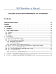
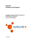
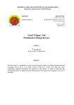
The ALICE PIT (Pixel Trigger) FED (Front End Device) server is software
developed to act as the driver layer of the PIT system.
It was developed in C++ to provide an interface to all hardware features and
to be the first layer of control of the system, it uses a ALICE DDL (digital data
link) to communicate with the hardware. It is able to receive commands from
several computers over the network, configuring the pixel rigger electronics,
providing hardware debugging tools, performing calibration procedures and
publishing status information on the system ensuring the trigger quality. It
runs in a Linux machine with SLC4 and ALICE Date distribution.
Configuration
DB
Fed server
(Linux)
DIM
PVSS w.
node
(Windows)
PVSS operator
node (Windows)
DDL
Trigger
Crate
CANbus
1 FED Software
1.1 Libraries Used
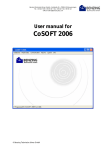
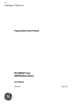
The PIT FED server was developed on top of CERN standard libraries used in
its communication layer and in the hardware access with the detector
electronics:
3
PVSS Worker
Node
CTP
Configuration
DB
DIM
OCCI
Loggers
Log4Cpp
FEE2Rorc
PIT Electronics
DIM: Developed at CERN stands for Distributed Information Management
System. It provides a network transparent inter-process communication layer.
It is used by the SPD FED to publish status information and to receive
commands from other computers through the network.
Clara Gaspar, DIM; http://dim.web.cern.ch/dim/
OCCI: Oracle C++ Call Interface (OCCI) is a high-performance and
comprehensive object-oriented API to access the Oracle databases. It is used
by the FED to access the DCS configuration database.
OCCI, Oracle C++ Call Interface: http://www.oracle.com/technology/tech/oci/occi/index.html
Log4cpp: Is a library of C++ classes for flexible logging to files, syslog, IDSA
and other destinations. It is modelled after the Log4j Java library, profiting of
their API as much as possible. It is used for the extensive logging that exists
in all operations of the FED.
Fee2Rorc: Developed at CERN, part of the standard ALICE Data Acquisition
and Test Environment (DATE) distribution, is a thin wrapper over the RORC
driver libraries and is used by the lower level of the software to access the
hardware using the DDL/SIU interface.
Log4cpp source forge :http://log4cpp.sourceforge.net/
1.2 Development Environment
4
The PIT FED server was developed using IDE. It is a workspace composed by
2 projects:
pixeltrigger: Top level project containing the DIM interface to PVSS. This
project parses all FED commands and contains references of all classes
PitDbConfiguration: Project containing database access abstraction
classes. Contains classes to manage the PIT configuration. Manages all
database tables with versioning.
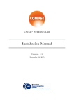
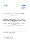
1.3 Project Dependencies
Here is the diagram of the projects dependencies in the PIT FED software.
log4cpp
pixeltrigger
PitDbConfiguration
dim
occi
clntsh
pthread
1.4 Library Versions
Library
Comment
Version
Gcc
Gnu Compiler Collection
3.04.00006
Dim
Dim communication layer version
17.01
Oracle Instant Client
Oracle interface
10.2.0.1
Log4cpp
Logging library
1.0.0
2 FED Installation
2.1 Software Dependencies
To install the SPD FED server in a machine please make sure to install the
following software first with all environment variables correctly defined.
5
2.1.1 Log4cpp Installation
Usually log4cpp comes with DATE installation, if it is not there you can ask
DATE support to install it. You can also try to install it yourself, even without
root permissions by following the instruction in the following web site:
http://log4cpp.sourceforge.net/
2.1.2 Oracle Instant Client Installation
For the SPD FED server we will need Oracle instant client version 10.2.xx.xx.
If you have root access in this machine you can try to get an rpm, which will
do most of the work for you. If you do not have root permissions or the rpm
does not work perform the following steps:
•
download Instant Client from the Oracle web site:
http://www.oracle.com/technology/software/tech/oci/instantclient/htdoc
s/linuxsoft.html. The recommended version is 10.2.04.
•
Unzip the instant-client to a known location ex:
“/home/pixeltrigger/bin/oracle/instantclient_10_2”
•
Add the database servers that the FED uses to the file tnsnames.ora,
you can start by copying the one from the DFS path:
G:\Aplications\Oracle\ADMIN to the instant client folder. This contains
all CERN Oracle servers maintained by the IT department, just check if
your server exists there, if not add it yourself.
•
Configure the environment variables:You will need to create 2 new
environment variables; TNS_ADMIN with the path where you have put
the tnsnames.ora file and the ORACLE_HOME with the path where you
installed the oracle instant-client. You will need also to add the path
where the oracle instant-client was installed to the PATH and to the
LD_LIBRARY_PATH variables.
•
If it is a development machine please unzip the SDK to the instant
client path and add the correct include and library paths to the Eclipse
projects configuration.
2.1.3 DIM
DIM comes installed by default in a DATE machine. You just need to configure
the correct dim DNS by editing the DIM_DNS_NODE environment variable.
Configure Eclipse with the includes and the libs paths if it is a development
machine.
2.1.4 Fee2Rorc
Fee2Rorc comes also with the standard DATE distribution. You will only need
to check the include files for the Eclipse IDE.
6
2.2 Installing the Software
2.2.1 Moving the software
If you are sure that the machine where you want to install the FED server is
running SLC4 with the same DATE distribution as the development machine
at the DSF then you just need to copy the software, if not its better to
compile the software instead. In order to do so compile a version of the
PIT FED, go to the Eclipse workspace path and get the following files:
•
pixeltrigger/Debug/pixeltrigger : the pixeltrigger executable
•
pixeltrigger/src/coordinatesTable.txt : Coordinates lookup table file
•
pixeltrigger/src/linkConfiguration.txt: link configuration file
•
PitDbConfiguration/Debug/libPitDbConfiguration.so: The pixel
trigger database configuration library
copy these files to a known location. Add the path to where you've copied the
libPitDbConfiguration.so file to the LD_LIBRARY_PATH. Finally edit
pit_configuration.ini with the correct settings and the other configuration files
if needed. And that's it, try to run the executable to see if it is working.
2.2.2 Compiling the software
To compile the software in the destination machine instead of just moving it
to the following:
•
Go to the Eclipse workspace path and copy the source folders and the
output folders of both pixeltrigger and PitDbConfiguration projects ex.:
pixeltrigger/src/, pixeltrigger/Debug/
•
Go to where you copied the output folders of both projects and in each
one of them run the following commands :
make clean
make all
•
Add the path where the libPitDbConfiguration.so is located to the
LD_LIBRARY_PATH
2.2.3 PIT FED Ini File
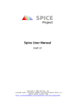
After moving the FED server you now need to configure some generic settings in the ini file. Open
the pit_configuration.ini file and you should see something like this:
7
[Data Base]
conString=DEVDB10
user = ALICE_DCS_SPDTRG
passwd = pixel456
################link coordinates Area#############################
# this changes how the links in the optin boards are assigned to sector, side,
halfstave
[Coordinates table]
fromDataBase=false
database or not
# tells if we load the coordinate table from the
# if the fromDataBase is set to false then here we can specify a coordinate
table file
configurationFile=./src/coordinatesTable.txt
[link configuration]
fromDataBase=false
database or not
# tells if we load the coordinate table from the
dbVersionNumber= 1
in the db to use
# if the fromDataBase is set to true then which version
# if the fromDataBase is set to false then here we can specify a coordinate
table file
configurationFile=./src/linkConfiguration.txt
Table with the available categories and settings.
DataBase category
conString
Connection string, defines a Oracle database server.
Look at tnsnames.ora file to find out about available
connection strings
User
User name for the database connection
Passwd
Database password for the corresponding user
Coordinates table
category
8
fromDatabase
If true then loads the coordinates lookup table from
the database, if false then loads then from a file
configurationFile
Defines the file from where to load the coordinates
Link Configuration
category
fromDatabase
If true then loads the link settings from the
database, if false then loads then from a file
DbVersionNumber
Defines which link database version to load at the
start of the fed
ConfigurationFile
If the fromDatabase is equal to false them this
defines which file to load the link settings from
2.2.5 PIT Coordinates file format
This file is used as a lookup table for the hardware to get from hardware
coordinates (board,link) to the detector coordinates (sector,side,halfstave).
Its a white space separated table with each line containing: board, link,
sector, side, halfstave settings for one link ex. :
#coordinate file table
#
board
link
sector
side
halfstave
0
0
0
A
0
0
1
0
A
1
2.2.6 Link Configuration file format
Its a file used to configure the link settings on the initialization of the FED
server.
Its a white space separated file with each line containing: sector, side,
halfstave, required fastors, link delay ex.:
#required fastors file table
# sector
side
halfstave
requiredFO
link delays
0
A
0
1100000001
0
0
A
1
0000000000
0
in the required fastor setting its a 10 bit binary number the left most value
corresponds to chip 0. for example “1100000000” means that only chip 0 and
chip 1 are active for triggering in this channel.
2.2.7 Example of the .bashrc file
Here is an example for the .bashrc file to make the PIT fed server run. Here
you can find the definition of all environment variables.
9
export DIM_DNS_NODE=spdfed0.cern.ch
export DIMDIR=/opt/dim
export LD_LIBRARY_PATH=/opt/dim/linux
export LD_LIBRARY_PATH=${LD_LIBRARY_PATH}:/home/pixeltrigger/log4cpp1.0/src/.libs
export LD_LIBRARY_PATH=${LD_LIBRARY_PATH}:/opt/date/rorc/Linux
export LD_LIBRARY_PATH=${LD_LIBRARY_PATH}:/opt/date/fec/Linux
export LD_LIBRARY_PATH=${LD_LIBRARY_PATH}:/usr/local/lib
#this is the path for the PitDbConfiguration shared library
export LD_LIBRARY_PATH=$
{LD_LIBRARY_PATH}:/home/pixeltrigger/eclipse/workspace/PitDbConfiguration/Debug/
#Oracle settings
export LD_LIBRARY_PATH=$
{LD_LIBRARY_PATH}:/home/pixeltrigger/bin/oracle/instantclient_10_2
export TNS_ADMIN=/home/pixeltrigger/bin/oracle/instantclient_10_2
export ORACLE_HOME=/home/pixeltrigger/bin/oracle/instantclient_10_2
PATH=~/bin:/home/pixeltrigger/bin/oracle/instantclient_10_2:$PATH
3 FED Server DIM interface
3.1 FED Commands
3.1.1 Standard FED Commands
For the PIT FED a command structure was devised to be flexible, capable of
receiving a variable number of arguments, to accurately display the status of
the execution of all commands and to be capable of dealing with the fact that
several instances can send commands at the same time.
A command channel in the PIT FED is composed of a DIM command and 4
status informations brought through DIM services:
● Command: DIM command which is a white space separated string
containing the command to be executed followed by all its parameters
“command arg1 arg2..argN” ex: “write_register 0x18000 0xDEADBEEF”
● Command Status: DIM service with a string publishing the execution
status of the command, possible values are: “FINISHED”, “EXECUTING”,
“FAILED”
● Command Return: DIM service, an integer containing the return
value of the command if any. If the command would be reading a
10
register this service would contain, after finishing the command, the
actual register value.
● Command ID: DIM service integer containing an unique id for the
current command being executed, useful if several instances send
commands at the same time
Command DIM Commands
Comment
PIT/COMMAND
Command name: A string identifying the command to be executed
Command DIM Services
Comment
PIT/CMD_RETURN
Data Out: Integer service with the return value fo the last command
sent to the FED
PIT/CMD_STATUS
Command Status : Dim service displaying the execution status of
the FED commands, “EXECUTING”, “FINISHED”, “FAILED”
PIT/CMD_ID
Command ID : Displays the id of the command being executed, its
incremented on the start of each command.
3.1.2 CTP TINDET Commands
The CTP (Central Trigger Processor) during testing procedures needs to have
a handle on the pixel trigger output modes. In order to do so there is a special
DIM command called SPD/SET_OPTIONCODE where it can set directly the
mode (normal, toggler, random, signature) of all the 10 output PIT outputs.
3.2 Status Services
Connecting the SPD hardware to the rest of the world the SPD FED server
has to work also as one information hub of the system. Data that are
relevant to the overall stability of the system need to be constantly
monitored and passed quickly to the PVSS supervision layer for monitoring
purposes and Alarm generation. So in addition of the data that can be
retrieved trough commands both SPD FED servers publish a list of several
parallel DIM Services displaying extra information of the system.
3.2.1 Link Status Services
11
Link Status Services
Comment
PIT/SIDE_<A,C>/SECTOR_<0..9>/HALFSTAVE<0.
.6>/REQUIRED
Link Required: 120 DIM services, one per half-stave,
Displaying if there is at least one fastor required in this
channel
PIT/SIDE_<A,C>/SECTOR_<0..9>/HALFSTAVE<0.
.6>/LOCKED
Link Locked: 120 DIM services, one per half-stave,
displaying if the HP deserializer is locked or not. (if there is
some light coming out of the GOL chip)
PIT/SIDE_<A,C>/SECTOR_<0..9>/HALFSTAVE<0.
.6>/ERROR
Link Error : 120 DIM services, one per half-stave, displaying
if the fastor rate for this channel is between the normal
thresholds or not
PIT/FO_COUNTERS_SIDE_A
Fastor Counters for Side A: Big array containing all
600 counters for side A. Used by SPD FED server A
during Fastor calibration scans
PIT/FO_COUNTERS_SIDE_C
Fastor Counters for Side C: Big array containing
alls 600 counters couters for side C. Used by SPD FED
server C during Fastor calibration scans
3.2.2 Output Status Services
Output Status Services
Comment
SPD/STATUS_OPTIOCODE
TinDet Outputs Option Codes: one dim service displaying
an array with the ouput modes (nomal, toggle, signature,
random)
PIT/PROCESSING/MODE_OUTPUT_<0..9>
Output Modes: 10 dim services, one per output, displaying a
string with the mode of the output
PIT/PROCESSING/COUNTER_OUTPUT_<0..9>
Output Counter: 10 dim services, one per output,
containing the FPGA counter register from the last
time that the “stop counters” command was sent
PIT/PROCESSING/COUNTER_RATE_<0..9>
Output Counter: 10 dim services, one per output,
containing the output trigger rate in Hz from the last
time that the “stop counters” command was sent
PIT/PROCESSING/COUNTER_AVG_RATE_<0..9>
Output Counter: 10 dim services, one per output,
containing the output average rate in Hz counted
since the last time the counter where started (long
time ago)
12
PIT/PROCESSING/COUNTER_TOTAL_COUNTER
<0..9>
Output Total Counter: 10 dim services, one per
output, containing the counters in float values,
without the overflow of the FPGA.
PIT/PROCESSING/START_COUNTERS
Start of the Counters: One dim service displaying
the last time the counters where started. Useful for
trigger rate assessment
PIT/PROCESSING/COSMIC_ALGORITHM
Cosmic Algorithm Mode: Displays the selected
mode for the cosmic algorithm (output 9)
PIT/FO_COUNTERS_SIDE_A
Fastor Counters for Side A: Big array containing all
600 counters for side A. Used by SPD FED server A
during Fastor calibration scans
PIT/FO_COUNTERS_SIDE_C
Fastor Counters for Side C: Big array containing
alls 600 counters couters for side C. Used by SPD FED
server C during Fastor calibration scans
3.2.3 Fastor Calibration Services
FO Calibration Status Services
Comment
PIT/FO_COUNTERS_SIDE_A
Fastor Counters for Side A: Big array containing all
600 counters for side A. Used by SPD FED server A
during Fastor calibration scans
PIT/FO_COUNTERS_SIDE_C
Fastor Counters for Side C: Big array containing
alls 600 counters couters for side C. Used by SPD FED
server C during Fastor calibration scans
PIT/CMD_STATUS_FED_A
Command Status FED Server A: Dedicated
command status for FED server A to be used during
fastor Calibration runs
PIT/CMD_STATUS_FED_C
Command Status FED Server C: Dedicated
command status for FED server C to be used during
fastor Calibration runs
3.2.4 Log DIM Service
The PIT Fed Server sends logging information to the PVSS supervision layer or
any other system through the dim service PIT/LOG
LOG Service Name
13
Comment
Pit Log Dim service: Contains Logging information
from the PIT FED the threshold can be configured
using the
PIT/LOG
4 FED Command Line Interface
Using the high level architecture of the FED server allows sending commands
directly through a command line interface. This feature is managed by the
pit_keyboard class. It uses the “termios.h” and “poll.h” unix C libraries to
scan from the keyboard input without stopping the execution loop of the FED
server. It is able to perform normal tasks and commands from other sources
at the same time while the operator types commands in the PIT FED console.
The command structure is the same as for the DIM commands, feedback of
the execution status is available by following one of the log channels of the
FED.
The command line interface was extremely useful during the early
commissioning phase for testing the hardware features and to perform bit
error rate measurements on the system.
5 List of FED Commands
all_self_masking_disable
Command to clear the masking enable bits for all chips
all_self_masking_enable
Command to set the masking enable bits for all chips
assign_chip_fomask
Command to set or unset mask on a chip (fastor channel)
Parameters:
sector
side
halfStave
chipNumber
maskValue
14
[0;1]
auto_check_phases
Command to auto check phases in all required locked links
auto_configure_delays
Command to auto configure delays in all required locked links
reset_bus_master
Command to reset the bus master interface in the control fpga
clear_chip_fomask
Command to clear the mask on a chip (fastor channel)
Parameters:
sector
side
halfStave
chipNumber
create_trigger_conditions_file
Command to create the file to be exported to offline
Parameters:
runNumber The file generated contains the run number received from
the DCS
export_trigger_conditions_file
Command to export to the file exchange server, if no file name is supplied it
will defaul to pit_dumpFile.txt
Parameters:
runNumber,fileName
15
get_firmware_version
Command that returns the processing firmware version currently loaded from
the database
get_link_conf_version
Command that returns the link configuration version currently loaded from
the database
load_firmware_db_conf
Command to load a new database configuration for the processing FPGA
Parameters:
firmwareVersionNumber The version of the firmware to retrieve from
the database
load_link_coordinate_file
Command to load the link coordinate file
Parameters:
filename
load_link_db_conf
Command to load a new link database configuration
Parameters:
linkVersionNumber
retrieve from the database
The number of the links configuration to
load_link_settings_file
Command that makes the pit configuration layer load the masking and delays
for all links from a file (if used without filename it will reload the current
defaul configuration)aram filename
load_parameter_db_conf
Command to load a new parameter database configuration
16
Parameters:
parameterVersionNumber
save_link_conf_to_db
Command to save a new link configuration version, reads the hardware and if
there is no change does not do anything
save_parameter_conf_to_db
Command to save a new parameter configuration version, reads the
hardware and if there is no change does not do anything
fastor_transmission_test
Command to perform a number of Fast OR transmission loops returning the
total number of bit errors
Parameters:
numberRepetitions
sleepTime
fctl
Command to write a front end control word to the DDL (expert only)
find_noisy_chips
Command to read all FastOr counters and find FastOr noisy chips
Parameters:
minFastOrCounts
shown in the log
Minimum number of FO counts for a chip to be
force_fo_channel
Command to force (value=1) or release (value=0) a fastor channel, setting or
resetting the User Defined FO bit
Parameters:
17
sector
side
halfStave
chipNumber
value [0;1]
get_parameter_version
Command that returns the processing firmware parameters version currently
loaded from the database
get_link_counters_auto_en
Command to get the counters auto enablr
Parameters:
sector
side
halfStave
Returns:
autoEnableFlag
link_pooling_settings
Command to set the link pooling settings
Parameters:
enable
Pooling false or true
interval
read_link_delay
Command to read the delay from one optical link
Parameters:
sector
side
18
halfStave
read_error_counter
Command to read the error counter from one optical link
Parameters:
sector
side
halfStave
read_fo_mask
Command to get the fastor mask of one optical link
Parameters:
sector
side
halfStave
read_link_phase
Command to read the phase (modulo 4) of the communication stream of one
optical link
Parameters:
sector
side
halfStave
read_proc_timer_period
Command to read the timer period
Returns:
Period Pit timer period in number of BCs
read_self_masking
19
Command to read the masking enable bits from one optical link
Parameters:
sector
side
halfStave
read_link_time_stamp
Command to read one of the time stamp registers of an optical link
Parameters:
sector
side
halfStave
timeStampReg
Number of timestamp register [0-2] range
read_udf_enable
Command to read the user defined fastor enable bit of one optical link
Parameters:
sector
side
halfStave
refresh_link_status
Command to refresh status services and internal data members of one optical
link channel
Parameters:
sector
side
halfStave
set_link_counters_auto_en
20
Command to set the counters auto enablr
Parameters:
sector
side
halfStave
auto_enable
(0,1)
start_link_counters
Command to start link counters
Parameters:
sector
side
halfStave
stop_link_counters
Command to stop link counters
Parameters:
sector
side
halfStave
write_link_delay
Command to write the delay for one optical link
Parameters:
sector
side
halfStave
delay Delay value modulo 4 [0;3]
write_fo_mask
21
Command to write the fastor mask of one optical link
Parameters:
sector
side
halfStave
maskValue
0 or 1
write_self_masking
Command to write the masking enable bits of one optical link
Parameters:
sector
side
halfStave
maskingEnableBits
HEX (0x...) 10 bits, one per chip. 0 OFF, 1 ON
write_udf_enable
Command to write the user defined fastor status enable bit in the optical link
Parameters:
sector
side
halfstave
value 0 or 1
load_file_to_ctrl_sram
Loads a binary file to the control fpga sram
Parameters:
fileName
baseAddress
memory_access_test
22
WARNING: baseAddress is presently IGNORED
Command to perform a number of read write loops returning the total
number of bit errors
Parameters:
blockLength
initialAddress
finalAddress
addressIncrement
numberRepetitions
check_board_plugged
Command to check if a board is plugged or not (maybe not needed but left it
there )
Parameters:
sector
side
halfStave
is_optin_prog_done
Command to check if a optin board is being programmed or not
Parameters:
sector
side
halfStave
Returns:
booleanValue
read_aux_time_stamp
Command to read one of the aux time stamp registers from an optin board
Parameters:
sector
23
side
halfStave
auxTimeStampNumber
Auxiliar time stamp register [0-2]
read_max_fastor_counts
Command to read maximum fastor counts from an optin board
Parameters:
sector
side
halfStave
layer
chip
read_min_fastor_counts
Command to read minimum fastor counts from an optin board
Parameters:
sector
side
halfStave
layer
chip
refresh_optin_status
Refreshes the status of one optin board channel
Parameters:
sector
side
halfStave
reset_optin
24
Resets one OPTIN board
Parameters:
boardNumber
reset_optin_all
Resets all OPTIN boards
reset_optin_parameters
Resets the setting registers of optin board
Parameters:
boardNumber
start_optin_counters
Command to start counters of all links in one optin board
Parameters:
boardNumber
stop_optin_counters
Command to stop counters of all links in one optin board
Parameters:
boardNumber
write_max_fastor_counts
Command to write the maximum fastor counts to an optin board
Parameters:
sector
side
halfStave
layer
chip
25
value
write_min_fastor_counts
Command to write the min fastor counts to an optin board
Parameters:
sector
side
halfStave
layer
chip
value
get_algorithm_parameter
Command to get one parameter for one algorithm
Parameters:
algorithmNumber [0;9]
parameterNumber [0;2]
Returns:
parameterValue
get_cosmic_algorithm
Command to read the algorithm executed for the cosmic output
Returns:
cosmicAlgorithm [0;5]
mask_optin
Command to mask one optin board from the read out of the processing fpga
Parameters:
boardNumber
26
is_proc_prog_done
Command to check if the processing fpga is programmed or not
Returns:
booleanValue
read_proc_cmd
Command to read the command register of the processing fpga
Returns:
commandCode Last command executed
read_proc_counter
Command to read one counter output in the processing fpga
Parameters:
outputCounterNumber
[0;9]
read_proc_gen_counter
Command read a general purpose counter in the processing fpga
Parameters:
counterNumber
read_proc_settings
Command to read one settings register of the processing fpga
Parameters:
settingRegisterNumber
[0-9]
read_proc_signature
Command to read a signature register from processing fpga
Parameters:
outputNumber
Returns:
27
[0;9]
Signature
read_proc_status
Command to read the one of the status register of the processing fpga
Parameters:
statusRegisterNumber
read_proc_time_stamp
Command to read a time stamp from the processing fpga
Parameters:
timeStampNumber
[0;2]
read_trigger_mode
Command to read the trigger mode for one output
Parameters:
outputNumber
Returns:
mode [0;3]
read_proc_firmware_version
Command to read the version register content
reset_proc_fpga
Resets the processing fpga (not the configuration nor the parameters)
reset_proc_fpga_parameters
Resets the configuration registers and ALL PARAMETERS of the processing
fpga
set_algorithm_parameter
28
Command to set one parameter for one algorithm
Parameters:
algorithmNumber [0;9]
parameterNumber [0;2]
parameterValue
set_all_algorithm_parameters
Command to set all 3 parameters for one algorithm
Parameters:
algorithmNumber[0;9]
par0 Parameter 0 value
par1 Parameter 1 value
par2 Parameter 2 value
set_cosmic_algorithm
Command to set the algorithm for the cosmic output (output 9, 0SCO)
Parameters:
algorithmNumber [0;5]
set_proc_timer_enable
Command to set the timer enable bit
Parameters:
value [0;1]
start_proc_counter
Command to start a counter in the processing fpga
stop_proc_counter
Command to stop a counter in the processing fpga
29
unmask_optin
Command to unmask one optin board from the read out of the processing
fpga
Parameters:
boardNumber
write_proc_cmd
Command to write in the command register of the processing fpga
Parameters:
commandCode
write_proc_settings
Command to write one of the settings register of the processing fpga
Parameters:
settingRegisterNumber
[0;9]
value
write_proc_timer_period
Command to write the timer period in the fpga
Parameters:
timerPeriod
write_trigger_mode
Command to write the trigger mode for one output
Parameters:
outputNumber
[0;9]
mode (normal, toggle, signature, random)
write_trigger_mode_num
Command to write the trigger mode for one output
30
Parameters:
outputNumber
[0;9]
mode [0;3]
program_proc_fpga
Programs the the processing FPGA using a ACE file
Parameters:
aceFileName
execute_ace_file
Sends a command to the programmer to execute an ACE file
Parameters:
aceFileName,jtagSelector
read_programmer_base_address
Reads the value of the programmer register containing the base ram address
Returns:
baseAddress
read_programmer_clk_division
Reads the value of the JTAG programmer clk_division register
Returns:
clkDivision
read_programmer_jtag_selector
Reads the value of the JTAG programmer jtagSelector field
Returns:
jtagSelector
read_programmer_status
31
Reads the status of the programmer, for the moment only logs the data
Returns:
programmerStatus Status word of the JTAG programmer
start_programmer
Starts the execution of the ACE file to program the processing FPGA
write_programmer_base_address
Writes the value of the programmer base ram address field
Parameters:
baseRamAddress
write_programmer_clk_division
Writes the value of the JTAG programmer clk_division register
Parameters:
clkDivision
write_programmer_jtag_selector
Writes the value of the programmer jtagSelector field
Parameters:
jtagSelector
reset_qpll
Command to reset the QPLL chip
rate_measuring_settings
Command to change set the rate measuring settings
Parameters:
enable,interval
32
read_fo_counter
Command to read the fastor counter of a fastor channel channel
Parameters:
sector
side
halfStave
chipNumber
read_word
Command to read from a memory position
Parameters:
address
Address in the PIT address space
refresh_clk_status
Command to refresh the DIM services showing status of QPLL, TTCRx and
clock locked
refresh_fo_status
Command to refresh services and menbers of one fastor channel channel
Parameters:
sector
side
halfStave
chipNumber
refresh_fo_counters
Command to refresh both dim services with the fastor counters
refresh_global_status
Command to refresh all status services and internal members of the pit driver
33
release_fo_channel
Command to release a fastor channel, resets the User defined FO bit
Parameters:
sector
side
halfStave
chipNumber
scan_clock_delay
Command to scan the clock delay and measure phases
Parameters:
referenceLink
reference in the report
Reference link the phase of which is used as
firstTtcrxDelay
First value to set in the TTCRx Delay register
finalTtcrxDelay
Last value to set in the TTCRx Delay register
delayStep
Difference between consecutive delay values
set_dim_log_threshold
Command to set the logging level of the logging dim appender logging
Parameters:
threshold
(debug,info,notice,warn,error,crit,alert,fatal)
set_file_log_threshold
Command to set the logging level of the logging file appender logging
Parameters:
threshold
(debug,info,notice,warn,error,crit,alert,fatal)
reset_siu
Command to reset the SIU card in case of problems
34
start_all_counters
Command to start ALL PIT counters
start_focounters_for_fed
Command to start fastor counters for one spd fed server, used in fastor
calibrations scans
Parameters:
side
Select the side (spdFed) A or C
stop_all_counters
Command to stop ALL PIT counters
stop_focounters_for_fed
Command to stop fastor counters for one spd fed server, updates the service
with fastor counters automaticaly
Parameters:
side
Select the side (spdFed) A or C
strd
Command to read from a status word from DDL (expert only)
test_ttcrx_access
Launches a test of write/read accesses to the TTCRx register
Parameters:
numRepetitions
registerNumber
read_ttcrx_finedelay
Reads the value of the Fine Delay 1 register of the TTCR.
35
Returns:
FineDelayValue
read_ttcrx_delay
Reads the value of the Fine Delay 1 register of the TTCRx, converts to integer
steps and absolute delay
Returns:
stepValue
read_ttcrx_register
Reads the value of a TTCRx register
Parameters:
registerNumber
Returns:
registerValue
reset_ttcrx_pin
Command to reset the TTCRx chip
scan_ttcrx_address
Scan the I2C bus to find the I2C address of the TTCRX chip. Data members
are set automatically
write_ttcrx_finedelay
Writes a value to the Fine Delay 1 register of the TTCRx
Parameters:
NewFineDelayValue
write_ttcrx_delay
Write the proper value to the Fine Delay 1 register of the TTCRx calculated
from the delay parameter expressed in number of steps
36
Parameters:
stepValue
write_ttcrx_register
Write a value to a register of the TTCRx
Parameters:
registerNumber
registerValue
write_word
Command to write to a memory position
Parameters:
address
Address in the PIT address space
value Value to write
37