1
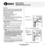
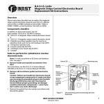
C7GPC121 C7GPC241 C9GPC131 C9GPC261 Gas Pasta Cooker with Cabinet Luxury Gas Range Series (Engineering Version) User’s Manual Dear Client & User, Firstly, thanks for purchasing and using our product. All the information and guidelines of this user’s manual comply with certain applicable regulations, which come out from our long-term accumulated knowledge and experience as well as current project development situations. Limited to some special structures, additional specified items or new technology changes, the actual usage situation might be some different from what stated in this user’s manual. Should you have any question, please do not hesitate to contact the manufacturer via the method shown in back cover page of this manual. For safety purpose and efficient operation, please make this document available to users for reference. Do have them to read this manual carefully before carry out any action on this device, especially when starting. The manufacturer declines any responsibility in the event users do not follow the instructions or guidelines stated here. The user’s manual should be placed close to the device, in convenience of users’ reading before operation. We have the full authority to reserve the further technical changes of the device, in the scope of further performance improvement characteristic development. Warning Any self-modification, wrong installation, adjustment or maintenance can lead to property loss or casualty. Please contact the manufacturer for any adjustment or maintenance, and have the work done by a trained & qualified person. For your safety sake, please keep the machine away from any liquid, gas or other object, which is flammable or explosive. This appliance should not be operated by those who have physiological, perceptual or mental disabilities or those who have insufficient experience or knowledge (including children). Only in conditions of being given sufficient supervise & guarantee of personal safety, as well as proper instructions & guidance, those who were mentioned above can make some particular operation of this device. Keep children away from the device. Preserve this manual safely. When passing on/selling the device to a third party, the manuals must be handed over along with the device. All users must operate the device complying with the user’s manual and related safety guidelines. If this appliance is placed near walls, partitions or kitchen furniture and the like, it is advisable to make these facilities with non-combustible material, otherwise cover them with non-combustible heat-resistant material, and pay attention to fire prevention regulations. The appliance should be installed in a well-ventilated area, if possible under a vent hood, in compliance with all applicable regulations in force. This will ensure that all burnt gases produced during the combustion process are completely exhausted. The appliance is only applicable to low-pressure gas regulating valve. It may cause property loss or safety accidents if high or medium pressure regulating valve is used. Do not dry heat the appliance. Fire warning: If you smell the gas, please keep away from any fire source. Do not light up any device or touch the electronic switch. Do not use any phone in the building either. Close the main gas valve immediately and call the professional personnel to maintain it. Operate by force or maintain improperly will lead to large gas leakage or deflagration easily. The manufacturer won’t bear any responsibility for fire hazard caused by improper operation or maintenance. Contents 1. Functional Introduction...................................................1 2. Structure Schematic Diagram........................................1 3. Basic Features & Parameters........................................5 4. Precautions & Recommendations..................................6 5. Working Instructions & Operation Flow..........................8 6. Routine Inspection.........................................................11 7. Cleaning & Maintenance................................................11 8. Failure Analysis & Trouble Shooting..............................12 1. Functional Introduction This product is manufactured by our company, which is combined with advantages from home and abroad. It is novel in design, reasonable in structure, easy in operation, durable in using and convenient in maintenance. Therefore, it is the ideal equipment for hotel, supermarket, restaurant, western restaurant, fast-food restaurant and food industry. 2. Structure Schematic Diagram Structure Schematic Diagram: C7GPC121 C7GPC241 C9GPC131 C9GPC261 3. Basic Features & Parameters Model C7GPC121 C9GPC131 C7GPC241 C9GPC261 Dimension(mm) 400×700×850+60 400×900×850+60 800×700×850+60 800×900×850+60 Thermal Power(kW) 11 11 22 22 LPG 11 11 22 22 NG 11 11 22 22 Town Gas 11 11 22 22 LPG 2.93kg/h 2.93kg/h 5.86kg/h 5.86kg/h NG 2.2M³h 2.2M³h 4.4M³h 4.4M³h Town Gas 5.4M³h 5.4M³h 10.8M³h 10.8M³h Capacity 28L 38L 28L×2 38L×2 Basket 2 3 4 6 Power(kW) Gas Consumption Nozzle Table: Gas Type Nozzle Diameter NG 2000(Pa) φ1.85 LPG 2800(Pa) φ1.25 Town Gas 1000(Pa) φ4.5 Note: When replacing, requirements in the aforementioned table must be observed. If unlisted gas is used, please contact the manufacturer or supplier directly. Substitution should be done by professional personnel. 4. Precautions & Recommendations 4.1 Transportation and Storage During transportation, the machine should be carefully handled and do not put it upside down to prevent from damaging to the shell and inside. The packaged machine should be stored in a ventilated warehouse without corrosive gas. If it needs to be stored in open air temporarily, measurement against raining is needed. 4.2 Notice for Installment 1. Installation should be done by professional technician. 2. Take out the attached battery, turn the pulse button counterclockwise, then put in the battery in the correct direction as shown and tighten the pulse button. 3. Appliance connection should conform to provisions in gas safety, installation and operation. 4. The appliance should be installed separately or assembled with other devices in accordance with provisions. 5. The appliance is not suitable for built-in installation. 6. The appliance should keep a minimum clearance of 10cm away from non-combustible substance (e.g. walls, windows etc.) on both sides, and 20cm at its back. Do not install the appliance on flammable floor or materials. 7. During installation, please consider the weight of the appliance. It is advisable to install on the floor. 8. The appliance should be installed in a well-ventilated area, if possible under a vent hood, in compliance with all applicable regulations in force. This will ensure that all burnt gases produced during the combustion process are completely exhausted. 9. After installation, keep the appliance stable and level. Do not tilt or sway during operation. 10. Before installation, remove the outer plastic films. 11. Do not use gas that not applicable to the appliance as fuel, neither does high-pressure or medium-pressure regulating valve. (This appliance is only applicable to low-pressure regulating valve.) 12. Before installation, a quick acting disconnecting valve should be installed upstream the appliance where is easy to reach. 13. Making sure the applicable gas is the same as the supplied one. If not, stop using. 14. Pipeline connected to the appliance should be connected with proper metal pipe. 15. If the pressure of the gas pipeline is 10% higher or lower than the rated pressure the appliance required, a regulator should be installed to ensure it reaches the rated value. 16. After connecting the appliance to the gas system, check for leaks at joints and pipe fittings; to do so, use soapy water or a specific leak detector (spray). “No Flaming!” 17. Check the gas supply pressure after installation. 18. Gas supply pressure can be measured with a liquid-filled pressure gauge (e.g. a U-shaped pressure gauge, minimum scale division 0.1mbar) or a digital gauge. Procedure as follows: Remove the panel, unscrew the screw on the pressure port (Picture 2); Place the pressure gauge; Start up the appliance by following the instructions in the user’s manual; Check the supply pressure; After the check, remove the pressure gauge; Replace the sealing screw. sealing screw pressure port Picture 2 4.3 Special Notice 1. 2. Installation, initial use and maintenance should be done by professional or licensed personnel or franchised person approved by manufacturer. Please keep the integrity of the appliance and remove the outer packaging. If you do have any questions, call the specialist and stop using the appliance. To avoid danger, keep the packing materials away from children. (For the materials are plastic bags, 3. nails etc.) For initial use, the duration of ignition may be a little longer due to the air existing in the new pipeline. If it cannot be lit up for the first time, turn the ignition switch off and 4. turn it on 3 minutes later to prevent from deflagration. Do not use gas that not applicable to the appliance as fuel, neither does high-pressure or medium-pressure regulating valve. Making sure the applicable gas 5. 6. 7. is the same as the supplied one, if not, stop using. To avoid hazard, turn the appliance off if not going to used it or if it is unattended. This product is a commercial machine that needs to be operated by trained personnel, not applicable for household use. This product is only for commercial use, not suitable for other uses, or it may cause danger. 8. This appliance is only designed for pasta or noodle cooking, not applicable for other 9. uses. During operation, the basin should be filled with water. Do not dry heat the appliance, otherwise, the basin may be burnt out. 10. Water or soup used for food cooking should be renewed regularly, and the basin should be cleaned timely. 11. Do not sway or tilt the appliance during operation. 12. Do not dismantle or self-modify the appliance. Dismantlement and self-modification may cause casualty. 13. Do not pat the product or put any heavy objects onto it. Abnormal operation may lead to appliance damage and danger. 14. Do not place any objects in the vent of the gas heater. Obstruction of smoke exhaustion may do harm to health. 15. High temperature may cause scald. Do not touch the appliance directly with hands due to high temperature during or after operation. 16. Do not destroy the control panel with hard or sharp objects. 17. Do not aim at the appliance with water jet during cleaning. 18. To prevent surface oxidation and chemical interaction, the stainless steel surfaces should be cleaned appropriately and regularly. 19. This appliance is verified by laboratory, satisfactory performance is guaranteed. To save energy, please avoid operating the appliance in circumstance of not cooking food or in bad performance. 5. Working Instructions & Operation Flow 5.1 Control Panel: IGN ●OFF MAX MIN 5.2 Knob Control: Press down the control knob and rotate it counterclockwise to align “ ” with the salient point, then press down the knob and push the igniter to light up the pilot flame simultaneously (normal actuation of the safety valve after ignition is ensured by pressing down the knob). (Initial duration of ignition may be a little longer due to the air existing in the new pipeline. The pilot flame cannot be lit up normally until the air is exhausted completely.) After 20s of ignition, release the knob. Adjust the flame according to food requirement. for MAX while for MIN. 5.3 Flameout: Press down the control knob and rotate it clockwise to align ● with the salient point. Turn off the main gas supply. 5.4 Replacing the Main Nozzle:(see chart below) Prepare a cross-screwdriver and two proper open spanners. Discharge the control panel, nut, aluminum pipe, nozzle connector and two flat nuts, then remove the nozzle. Substitute with a matched one. Screw and fasten the two flat nuts, nozzle elbow, aluminum pipe and nut. Then replace the control panel and attach a new label to specify the new gas type. 5.5 Regulating the Air Inlet:(see chart below) To regulate the air inlet of burner, unscrew the two flat nuts and move the nozzle holder left and right. After adjustment, fasten the two nuts. 5.6 Replacing the Pilot Nozzle:(see chart below) Position a proper spanner on the nut of the pilot nozzle to balance the twisting stress. Discharge the screw fixing the thermocouple with a proper spanner and remove the thermocouple. Discharge the nut fixing the aluminum pipe and dismantle the pipe, then remove the nozzle. Substitute with an appropriate nozzle and replace the components. It is unnecessary to adjust the primary air. thermocouple pilot burner ignition needle ; pilot nozzle 6. Routine Inspection It is necessary to check the machine daily. Check the machine regularly can avoid serious accident happens. Stop using if user feels that there are some problems in the circuit or machine. Check the situation of the machine before or after using every day. Before using: Whether the machine is tilted? Whether the control panel is damaged? During using: Whether there is strange odor or vibration noise? Whether the burner flame is normal? Any light back or flameout? Whether the power is normal? 7. Cleaning & Maintenance 1. 2. 3. 4. 5. 6. 7. Before using, clean the basin and remove all the commercial grease. Cleaning can be carried out as follows: Fill the basin with water, add some detergent and boil for a few minutes. When it reaches 40-50 degrees, clean the grease in tank with a towel. Do not clean the tank with abrasive detergent, neither does scrape the surface with steel wire brush or sharp utensil. After cleaning, drain out the dirty water from the tap. Then rinse the basin with clear water. Do not aim at the appliance surface with water directly, neither does clean it with corrosive substances (Hydrochloric acid). Do not modify the air inlet volume required for combustion. If not going to use the appliance at any time, cut off the gas supply. If not going to use the appliance for a long period of time, clean its surfaces with a gasoline cloth and store it in a well-ventilated area. General inspection should be carried out at least once a year by professional personnel. 90% of the appliance is made of metal (stainless steel, iron, aluminum, galvanized metal sheet), which can be recycled by appointed treatment plant according to the environmental standards of the equipment installed countries in force. (No littering!) 8. Failure Analysis & Trouble Shooting Symptoms Causes 1. 2. The igniter does not work. Plug or plug cord of damaged. The pilot flame cannot be lit 3. 4. Pressure in gas pipeline is not enough. Pilot nozzle is blocked. up. 5. The thermocouple and valve is in bad igniter is contact. 6. The thermocouple is defective due to the pilot heating. The pilot flame is on but the main burner cannot be lit up. 7. Gas thermostatic valve is defective. 1. Pressure in gas pipeline is not enough. 2. 3. Main nozzle is blocked. Gas valve is defective. Aforementioned troubles are just for reference. If any failure occurs, please stop using and inform the professional technicians to check and repair. Safety is first and maintenance should be done after shutting down the power supply and gas supply.