1
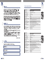
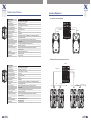
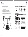
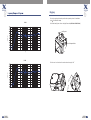
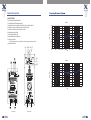
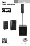
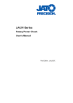
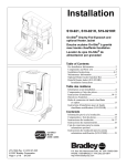
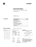
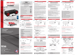
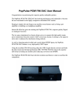
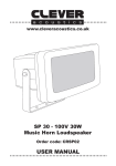
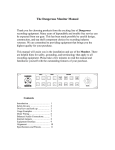
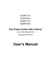
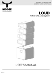
X
X 8A/10A/12A/15A
8
10
X
X
2
X
15
X
11
X
INDEX
INTRODUCTION
4
HOOKUP DIAGRAMS
QUICK START
5
RIGGING
PANEL DESCRIPTION
6
7
8
FREQUENCY RESPONSE DIAGRAM
10
WIRE CONNECTIONS
12
13
TECHNICAL SPECIFICATIONS
WARRANTY
15
* X 12A, X 15A are Active Speakers for
professional use , they can be used in following electromagnetic environment: residential,
commercial and light industrial, urban outdoors. They are the apparatusNot intended for
rack mounting.
* For X 12A, X 15A,the peak inrush current is 0.9A
*This device complies with part 15 of the FCC Rules. Operation is subject to the following
two conditions: (1)this device may not cause harmful interference , and (2)this device
must accept any interference received , including interference that may cause undesired
operation . Changes or modifications not expressly approved by the party responsible for
compliance could void the user's authority to operate the equipment.
NOTE: This equipment has been tested and found to comply with the limits for a Class B
digital device, pursuant to Part 15 of the FCC Rules.
These limits are designed to provide reasonable protection against harmful interference in
a residential installation. This equipment generates, uses and can radiate radio frequency
energy and, if not installed and used in accordance with the instructions, may cause
harmful interference to radio communications. However, there is no guarantee that
interference will not occur in a particular installation. If this equipment does cause harmful
interference to radio or television reception, which can be determined by turning the
equipment off and on, the user is encouraged to try to correct the interference by one or
more of the following measures:
-- Reorient or relocate the receiving antenna.
-- Increase the separation between the equipment and receiver.
-- Connect the equipment into an outlet on a circuit different from that to which the
receiver is connected.
-- Consult the dealer or an experienced radio/TV technician for help.
14
3
X
X
Technical Specifications
X
X
Model Active
X 12A
System Type
Transducer Low
Transducer High
o
o
Horn Coverage H XV
Frequency Response
Crossover Frequency
2-Way Active Vented Speaker
12" Woofer, 2" Voice Coil
1" Neodymium Driver, 1" Voice Coil
90oH x 60oV
60Hz-20KHz (-6dB)
2100Hz
118dB Max.
200W Continuous Bi-Amp Analog Processor(Low: 150W / High:50W),
PEAK 800W
Max SPL(1M)
Power system
Connector
External Controls
Line/Mic Input with Combo &Link with XLR
Volume Control/Line&Mic Switch/Contour on/Power on with Green
LED/ Clip Limiter with Red LED/Ground Lift.
Electronic Protections
Power Supply
Thermal/Overload/Analog Limiter/Compressor
110-120V~50/60Hz or 220-240V~50/60Hz Switchable
Plastic Cabinet, Trapezoidal & Monitor Shape, Metal Grille, Rubber
feet,3* Handles ( Top and both sides)
Enclosure Construction
Mounting
Dimensions (HxWxD)
Net Weight
36mm standard pole-mount
607*380*337mm
13.75kg/30.31 Ibs
Model Active
X 15A
System Type
Transducer Low
Transducer High
o
o
Horn Coverage H XV
Frequency Response
Crossover Frequency
2-Way Active Vented Speaker
15" Woofer, 2" Voice Coil
1" Neodymium Driver, 1" Voice Coil
90oH x 60oV
55Hz-20KHz(-6dB)
2100Hz
119dB Max.
Max SPL(1M)
Power system
Connector
Enclosure Controls
Electronic Protections
Power Supply
Enclosure Construction
Mounting
Dimensions (HxWxD)
Net Weight
4
10
200W Continuous,Bi-Amp Analog Processor(Low: 150W / High:50W),
PEAK 800W
Line/Mic Input With Combo &Link With XLR
Volume Control/Line&Mic Switch/Contour on/Power on with Green
LED/ Clip Limiter with Red LED/Ground Lift.
Thermal/Overload/Analog Limiter/Compressor
110-120V~50/60Hz or 220-240V~50/60Hz Switchable
Plastic Cabinet, Trapezoidal & Monitor Shape, Metal Grille, Rubber
feet,3* Handles (Top and both sides)
36mm standard pole-mount
625*386*366mm
14.86kg/32.80 Ibs
13
X
10
X
Technical Specifications
Model Active
System Type
Transducer Low
Transducer Driver
o
o
Horn Coverage H XV
Frequency Response
Crossover Frequency
Max SPL(1M)
Power system
Connector
External Controls
Electronic Protections
Power Supply
Enclosure Construction
Mounting
Dimensions (HxWxD)
Net Weight
X 8A
2-Way Active Vented Speaker
8" Woofer, 1.5"voice coil
1" Ferrite Twitter, 1" Voice Coil
o
o
90 H x 60 V
68Hz-20KHz (-6dB)
2000Hz
113dB Max.
4
Hookup Diagrams
Two speaker in stereo operation
MAIN OUT R
MAIN OUT L
LINE IN
LINE IN
Class D SMPS ( Bi-AMP , LF 90W/RMS + HF 30W/RMS), 480W Peak
Line In&Link With XLR
Volume Control/Power ON with Green LED//Clip Limiter
with Red LED
MIXER
Thermal/Overload/Analog limiter/Compressor
100V-240V ~50/60Hz
Plastic cabinet,Trapezoidal & Monitor shape,Metal grille,
1*Handle-On Top
36mm standard pole-mount
420*270*240 mm
5.53 kg/12.2lbs
Multiple speakers with the same stereo source
MIXER
Model Active
System Type
Transducer Low
Transducer Driver
Horn Coverage HoXVo
Frequency Response
Crossover Frequency
Max SPL(1M)
Power system
Connector
External Controls
Electronic Protections
Power Supply
Enclosure Construction
Mounting
Dimensions (HxWxD)
Net Weight
12
X 10A
2-Way Active Vented Speaker
10" Woofer, 1.5"voice coil
1" Ferrite Twitter, 1" Voice Coil
o
o
90 H x 60 V
65Hz-20KHz (-6dB)
1900Hz
116dB Max.
Class D SMPS ( Bi-AMP , LF 90W/RMS + HF 30W/RMS), 480W Peak
Line In&Link With XLR
Volume Control/Power ON with Green LED//Clip Limiter
with Red LED
MAIN OUT LEFT
LINK
LINE IN
MAIN OUT RIGHT
LINK TO NEXT SPEAKER
LINK
LINE IN
LINE IN
LINK TO NEXT SPEAKER
LINE IN
Thermal/Overload/Analog limiter/Compressor
100V-240V ~50/60Hz
Plastic cabinet,Trapezoidal & Monitor shape,Metal grille,
1*Handle-On Top
36mm standard pole-mount
460*285*265mm
6.92 (kg)/15.26lbs
Use only with a 250V fuse
Use only with a 250V fuse
Use only with a 250V fuse
Use only with a 250V fuse
5
X
5
X
Quick Start
Make all initial connections with all the equipments powered off, and ensure that all the
main volume controls are turned completely down.
9
1). Connect one side of the signal cable at your audio mixer into output left / right (with
Stereo- Jack or XLR) and the other side of the cable into the line input Stereo-Jack)
of your active speaker cabinet.
2). Connect the power cord to mains.
3). Turn on your mixer first, then the active speaker cabinets.
4). Turn up the volume control of the active speaker cabinets.
5). Use PFL function to get the proper input level for the mixer, and adjust the
main mix level control to manipulate the output level.
6). After using, turn off your active speaker cabinets first, then the mixer.
Signal Cable
Signal Cable
Power Cord
Power Cord
Tripod
Mount
Left
Main Mix
Output
Right
Main Mix
Output
Tripod
Mount
Mixer
6
11
X
X
8
Rigging
X 12A
The X series speaker cabinet also provides the suspension points for installation.
(M10 1.5PH LENGTH: 30mm).
For further details, please refer to the right illustration(OPTIONAL FUNCTIONAL)
6
Eye bolt
Suspension Point
X 15A
45 o
The floor use is as a function of a monitor when the angle is 45o
10
7
X
7
X
8
Panel Description
AMP INTERFACE
(1) BI-POLAR MAIN POWER SWITCH
(2) AC POWER SOCKET WITH MAIN FUSE
(3) LINE/MIC INPUT ON COMBO CONNECTOR (X 8A /10A ONLY LNE IN )
(4) MIX OUT ON XLR CONNECTOR (X 8A /10A ONLY LINK)
(5) "INPUT SENSITIVITY" SWITCH FOR LINE & MIC
(6) MAIN VOLUME CONTROL
(7) CLIP INDICATOR RED LED
(8) POWER INDICATOR GREEN LED
(9) CONTOUR ON/OFF
CONTOUR ON preset is to equalize the mix for optimal music play back
(10) GROUND SWITCH
X 8A
(3) (5) (4) (6) (7)
(8)
(9)
(10)
X 10A
Use only with a 250V fuse
(2)
X 8A / 10A
8
(1)
X 12A / 15A
9