1
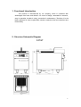
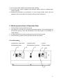
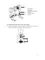
e
S
e
c
i
rv
Mastro GmbH
Hüserstraße 53
+49 (0) 23 81/ 973 71– 0
59075 Hamm / Germany
+49 (0) 23 81/ 973 71– 88
w w w . m a s t r o s h o p . c o m
Dear Client & User,
Firstly, thanks for purchasing and using our product. All the information and
guidelines of this user’s manual comply with certain applicable regulations, which come
out from our long-term accumulated knowledge and experience as well as current project
development situations.
Limited to some special structures, additional specified items or new technology
changes, the actual usage situation might be some different from what stated in this user’s
manual. Should you have any question, please do not hesitate to contact the
manufacturer via the method shown in back cover page of this manual.
For safety purpose and efficient operation, please make this document available to
users for reference. Do have them to read this manual carefully before carry out any action
on this device, especially when starting.
The manufacturer declines any responsibility in the event users do not follow
the instructions or guidelines stated here.
The user’s manual should be placed close to the device, in convenience of users’
reading before operation. We have the full authority to reserve the further technical
changes of the device, in the scope of further performance improvement characteristic
development.
2
Warning
Any self-modification, wrong installation, adjustment or maintenance can lead to
property loss or casualty. Please contact the manufacturer for any adjustment or
maintenance, and have the work done by a trained & qualified person.
For your safety sake, please keep the machine away from any liquid, gas or other
object, which is flammable or explosive.
The device should NOT be operated by those who have physiological, perceptual or
psychological barrier or disability, as well as those who are lack of necessary
knowledge or experience to use, including children. Only in conditions of being given
sufficient supervise & guarantee of personal safety, as well as proper instructions &
guidance, those who were mentioned above can make some particular operation of
this device.
Keep children away from the device.
Preserve this manual safely. When passing on/selling the device to a third party, the
manuals must be handed over along with the device. All users must operate the
device complying with the user’s manual and related safety guidelines.
If this appliance is placed near walls, partitions or kitchen furniture and the like, it is
advisable to make these facilities with non-combustible material, otherwise cover
them with non-combustible heat-resistant material, and pay attention to fire
prevention regulations.
The appliance should be installed in a well-ventilated area, if possible under a vent
hood, in compliance with all applicable regulations in force. This will ensure that all
burnt gases produced during the combustion process are completely exhausted.
The appliance is only applicable to low-pressure gas control valve. It may lead to loss
and casualty if you use other regulating valves.
Dry fry is not allowed!
Fire warning: If you smell the gas, please keep away from fire. Do not light up any
device or touch the electronic switch. Do not use any phone in the building either.
Close the main gas valve immediately and call the professional personnel to maintain
it. Operate by force or maintain improperly will lead to large gas leakage or
deflagration easily. The manufacturer won’t bear any responsibility for fire accidents
caused by improper operation or maintenance.
3
Contents
1.
Functional Introduction……………………………………5
2.
Structure Schematic Diagram……………………………5
3.
Basic Features & Parameters……………………………8
4.
Precautions & Recommendations ………………………9
5.
Working Instructions & Operation Flow…………………11
6.
Routine Inspection ………………………………………14
7.
Cleaning & Maintenance…………………………………14
8.
Failure Analysis & Trouble Shooting……………………15
4
1. Functional Introduction
This product is manufactured by our company, which is combined with
advantages from home and abroad. It is novel in design, reasonable in structure,
easy in operation, durable in using, convenient in maintenance. Therefore, it is the
ideal equipment for hotel, supermarket, western restaurant, fast food restaurant and
food industry.
2. Structure Schematic Diagram
F47GT
5
F77GT
F49G
6
F89G
7
3. Basic Features & Parameters
Model
F47GT
F77GT
F49G
Sizemm
400×700×850
700×700×850
400×900×850
800×900×850
Thermal PowerkW
15.5
15.5×2
15.5
15.5×2
LPG
15.5
15.5×2
15.5
15.5×2
NG
15.5
15.5×2
15.5
15.5×2
LPG
1.23kg/h
1.23kg/h×2
1.23kg/h
1.23kg/h×2
NG
1.56M³/h
1.56M³/h×2
1.56M³/h
1.56M³/h×2
Power
kW
Gas
Consumption
F89G
Town
Gas
Town
Gas
Capacity (L)
Basket Number
17±2+17±2
17±
1
2
20±
20±2+20±2
1
2
Nozzle list:
Gas Type
Nozzle Diameter
NG 2000Pa
φ1.8
LPG 2800Pa
φ1.15
Town Gas 1000Pa
φ4.0
NoticeWhile replacing the nozzle, please comply with the regulation above. If you use
any other gas type differs from those in the list, please contact the manufacturer
or the supplier directly. Replacement should be done by professional personnel.
8
4. Precautions & Recommendations
4.1 Transportation and Storage
During transportation, the machine should be carefully handled and do not put it
upside down to prevent from damaging to the shell and inside. The packaged
machine should be stored in a ventilated warehouse without corrosive gas. If it needs
to be stored in open air temporarily, measurement against raining is needed.
4.2 Notice for Installment
1. The installation should be operated by professional technician.
2. The appliance should be connected in accordance with all applicable regulations and
3.
4.
5.
6.
standards in force.
The appliance should be installed separately or assembled with other device in stated
range.
The appliance is not suitable for built-in installation.
The appliance should be kept a minimum clearance of 10cm away from the
incombustible object on both sides and 20cm at the back(such as walls, windows and
so on).Do not install it on the flammable floor or other combustible objects.
Consider the weight of the appliance, please install on the floor or countertop.
7. The appliance should be installed in a well-ventilated area, if possible under a vent
hood, in compliance with all applicable regulations in force. This will ensure that all
burnt gases produced during the combustion process are completely exhausted.
8. After installation, please place horizontally and keep firm. Do not sway when you are
using.
9. Before installation, please remove the outer film
10. Do not use gas which is not required as fuel. Neither do high pressure nor Medium
pressure regulating valves. (The appliance is only applicable to low pressure gas
regulating valve.)
11. A quick gas-shutting valve which should be installed above the appliance and easy to
reach is needed before installation.
12. Make sure the applicable gas is the same as the gas supply. If not, please stop using.
13. Please use metal pipe to connect the appliance.
14. If the gas pipe pressure is higher or lower than the rated pressure at 10%, please
install a pressure regulator to adjust the gas pressure.
15. After connecting the appliance to the gas system, check for leaks at joints and pipe
fittings; to do so, use soapy water or a specific leak detector (spray). “No flaming!”
16. Check the gas supply pressure after installation.
17. Gas supply pressure can be measured with a liquid-filled pressure gauge (for example,
a U-shaped pressure gauge, minimum scale division 0.1 mbar) or a digital gauge.
Procedure as follows:
Remove the panel, unscrew the screw on the pressure port (picture 2)
9
Place the pressure gauge
Start up the appliance by following the instructions in the user’s manual
Check supply pressure
After the check, remove the pressure gauge
Replace the sealing screw.
Sealing screw
Picture 2
Pressure port
4.3Special Notice
1. The appliance is a commercial machine which needs to be operated by professional
personnel or qualified person. Not applicable for home use.
2. Please keep the integrity of the appliance and remove the outer wrapping. If you have
any questions, call the specialist and stop using the appliance. In case of danger,
keep the wrapping materials away from children. (For the materials are plastic bags,
nails and so on.)
3. When first using, the duration of ignition is a little longer because of the air in the new
pipe. If the ignition cannot be light up, turn off the Ignition switch and turn it on 3
minutes later to prevent from deflagration.
4. In case of potential danger, the power should be turned off when finishing work.
5. The product is only for commercial use.
6. The appliance is only designed for edible oil or high-melting fat fry food.
7. Do not sway or tilt when using. Dismantlement or self-modification is not allowed.
8. Dismantlement or self-modification will cause casualty.
9. Do not pat the product and put heavy object onto the product. Neither does placing
any object in the smoke vent.
10. Abnormal operation may cause damage and danger
11. High temperature may cause scald.
12. Do not touch the appliance directly with hands due to high temperature during or after
the operation.
13. Do not destroy the control panel with hard or sharp objects.
10
14. Do not spray water directly to the product when cleaning.
15. To prevent from surface oxidation and chemism, please clean the stainless-steel
surface regularly.
16. Satisfactory performance is guaranteed. To save energy, please avoid using the
appliance under circumstance of finishing working or bad performance.
5. Working Instructions & Operation Flow
1. If the fuel tank is empty, please stop using.
2. The edible oil or fat used for fry should be renewed regularly. The reusable edible oil
will produce impurity, lower the inflammation point and increase the possibility of
sudden boiling.
3. If a large amount of food cannot absorb the oil, the hot oil may splash
4. If the oil burning, please turn the gas switch off and cover the lid.
5.1control panel
A temperature control knob
D temperature limiter
D
B ignition switch
E temperature control list
E
C igniter
F flameout switch
C
F
120
132
190
200
6
7
165
2
2
173
148
1
1
165
173
6
7
148
120
132
0
3 4 5
0
A
190
200
B
11
3 4 5
5.2Ignition:
Special notesThe ignition time may be a little longer for the first time because of the
air existing in the new pipe.
Turn the temperature control knob A to zero position.
Press the ignition switch B.Hold it there
Press igniter C (It will light automatically if it is a pulse igniter.) until the flame is lit up.
Hold the switch B for more than 20 seconds.
Release the switch B. (If flameout, please repeat the steps above.)
Turn the temperature control knob A to the temperature required according to the
temperature list.
5.3 Temperature control:
The main flame and gas supply will be turned off automatically and the temperature
will keep constant when it rises to the appointed one.
When the temperature drops to -10 , the main combustor will begin flaming
automatically and adjusting the temperature.
The appliance will repeat the work above automatically.
5.4 Flameout:
Press the flameout switch F to cut the combustion source.
Turn the main gas supply off.
Special notes: If you need to start the machine again after flameout, you should turn
the switch F off and ignite 1min later.
5.5 Replacing the nozzle:(see chart below)
All the operation should be done by profession people.
Discharge the nozzle of pilot flame B.
Discharge nozzle D.
Replace the nozzles of the main combustor and the pilot with those that match with
the gas.
Screw the nozzle; attach a new label with the new gas type written in it.
12
A
B
C
D
E
F
A combustor
B pilot flame
C blast volume regulator
D nozzle
E nozzle retainer
F isocon
5.6 Adjust the wind Inlet volume:see chart below
In principle, the damper is the max. Adjustment should be made if the flame is
unstable or combustion is incomplete by professional technician.
H
13
6. Routine Inspection
It is necessary to check the machine daily.
Check the machine regularly can avoid serious accident happens.
Stop using if user feels that there are some problems in the circuit or machine.
Check the situation of the machine before or after using every day.
Before using: Whether the machine is tilted?
Whether the control panel is damaged?
During using: Whether there is strange smell or vibration noise?
Whether the flame of the combustor is normal? Any light back or flameout?
Whether the power is normal?
7. Cleaning and Maintenance
1. Clean all the commercial grease before using as follows:
Add water and detergent into the tank and boil a few minutes, clean the grease
with towel when the water temperature rises to 40 to 50 Celsius degree.
Do not clean the tank with abrasive detergent or scrape it with wire brush or
anything sharp that may damage the tank.
Drain the dirty water from the tap after cleaning and clean the tank with clear
water.
2. Do not clean it with spraying water directly or caustic material (acid, alkali).
3. Put the high-melting grease into the tank separately after melting when using.
4. Food debris should be cleaned up promptly every day.
5. Clean the tank or drain the used oil off should be done when the oil temperature drops
to normal.
6. Oil should be added when it is under the lowest oil level permitted.
7. Do not change the wind inlet volume required.
8. Turn the gas supply off when disusing.
9. If not going to use the appliance for a long time, please turn off the gas supply.
Clean the surface with a gasoline cloth and store it in a well-ventilated warehouse with
no corrosive gas.
10. General inspection should be made at least once a year by professional personnel.
11. 90% of the appliance are metals (stainless steelIronAluminumgalvanized metal
sheet) which can be recycled by appointed treatment plant according to the
environmental standards of the equipment installation countries. (No Littering!)
14
8. Failure Analysis &Trouble Shooting
Troubles
Causes
1. The pulse igniter doesn’t work.
2. The plug gets off or the ceramic needle of the
The pilot
ignited.
flame
cannot
pilot damages.
3. The pressure in the gas pipe is not enough.
be
4. The nozzle is block.
5. The thermocouple is wrongly connected or the
temperature limiter is disconnected.
6. The thermocouple is damaged while heating.
7. Gas temperature control valve is defective.
1.
2.
3.
4.
The pressure in the gas pipe is not enough.
The nozzle is block.
The switch is defective.
The pilot flame is on but the
The temperature controller is defective or
main burner cannot be ignited.
disconnected.
5. The thermocouple and the valve are bad contact.
6. The thermocouple is defective.
Aforementioned troubles are just for reference. If any failure occurs,
please stop using, and inform the professional technicians to check and
repair. Safety is first and maintenance should be done after shut down
power supply and gas supply.
15