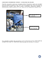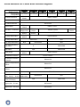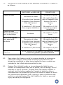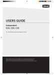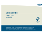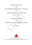
1
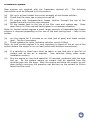
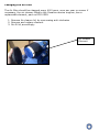
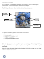
Canaline Marine Engines
Engine Models
Canaline 25
Canaline 30
Canaline 38
Canaline 42
Canaline 52
Canaline 60
Canaline operators handbook
Failure to read this or carry out the required service programme may invalidate your warranty
Index
Introduction
4
Engine Identification
5
Safety precautions
6
Canal Boat Specification
8
Starting / Stopping
9
Fuel and Oil Specifications
12
Maintenance Schedule
15
Installation Information
Wiring diagrams
Anti Vibration Mounts / Alignment installation
Calorfier Connections / Position
PRM 80/120 Cable installation
23
29
31
33
Fast Moving Parts list
34
UK Dealer Network
35
RCD Certificate
36
Warranty Terms and conditions
37
Service Record
40
Warranty registration card
Loose
Introduction
This Canaline Marine diesel engine is based on the Kioti diesel engine which is
manufactured by the Daedong Industrial Co Ltd.
Engines Plus Ltd wishes to thank you for purchasing your new Canaline Marine
Diesel engine. Your new engine is the result of many years of research and
development and high quality manufacturing, this engine is designed based on
strict quality standards established by the unit assuring quality of Kioti genuine
components. Its knowledge on the operation of the diesel engine is based on
faithful services and reliability for years. This manual makes users familiar with
the diesel engine and provides useful information on safety, operation, and
maintenance of the diesel engine.
To get the fullest use and benefit from your marine engine, it is important that
you install, operate and maintain it correctly. This manual, along with gearbox
operators’ handbook, is designed to help you do this.
Please read this manual carefully and follow its operating maintenance
recommendations, along with the installation guidelines. This will ensure many
years of trouble-free and economical engine operation.
Should you require further advice, technical assistance or an engine service,
please contact your nearest marine engine outlet, he knows your engine best and
is ready to meet your requirements.
On completion of the warranty registration card, you will receive a warranty
certificate which forms part of your warranty agreement with Engines Plus Ltd
All information, illustrations, and specifications contained in this Manual are based
on the latest product information available at the time of publication.
Engines Plus Ltd is a mariniser of industrial diesel engines, of which the Canaline
product is part of our product portfolio. Engines Plus Ltd produces this manual for
use on the Canaline marine engine based on the Kioti Diesel engine.
Engines Plus Ltd reserves the right to make changes in this manual at any time
without prior notice.
The information given is subject to the company’s current conditions of Tender
and Sale, is for the assistance of users, and is based upon results obtained from
tests carried out at the place of manufacture and in vessels used for development
purposes. We do not guarantee the same results will be obtained elsewhere
under different conditions.
4
Engine Identification
NOTE: In all communications with the Engines Plus Ltd or a local dealer the
engine serial number and engine type must be quoted.
The engine serial number is on the top of the engine, on a designated number
plate.
As part of your engine warranty please return your registration card, which is
supplied loose, as soon as possible.
Engine Information
Fill in your engine information below, so you have it to hand when contacting
your local dealer.
Engine Type:
EP Serial No:
Gearbox Type:
Gearbox Number:
Date of Installation:
5
Safety Precautions
Keep the engine, gearbox and surrounding area clean, including the area
immediately below the engine.
Drives – Power Take Off Areas
Gearbox Output Flange
The purpose of the marine diesel propulsion engine is to provide motive
power to propel a vessel. Accordingly the gearbox output shaft rotates at
between 133 and 2400rev/min. This flange is designed to be coupled to a
propeller shaft by the installer and steps must be taken to ensure adequate
guarding.
Forward End Drive
Engines are supplied with unguarded vee and poly vee belt drives to power
the fresh water pump and battery-charging alternator. The installer must
ensure that it is not possible for injury to occur by allowing accessibility to this
area of the engine. The pulleys run at high speed and can cause injury if
personnel or clothing come in contact with the belts or pulleys, when the
engine is running.
Exhaust
Exhaust Outlet
Diesel marine propulsion engines emit exhaust gases at very high
temperatures – around 400 - 500°C. Engines are supplied with either wet
exhaust outlet (water injection bend) or dry outlet (dry exhaust stub) – see
engine price list. At the outlet next to the heat exchange header tank, the
exhaust outlet can become very hot and if touched, can injure. This must be
lagged or avoided by ensuring adequate guarding. It is the responsibility of
the installer to lag the exhaust system if a dry system is used. Exhaust gases
are harmful if ingested, the installer must therefore ensure that exhaust lines
are lead overboard and that leakage in the vessel does not occur.
Fuel
Fuel Lines
Diesel engines are equipped with high pressure fuel injection pumps, if
leakage should occur, or if pipes fracture, fuel at high pressure can harm
personnel. Skin must be thoroughly cleaned in the event of contact with
diesel fuel.
Fuel Supply Connections
Engines are supplied with 8mm compression fittings. The installer must
ensure that when connections are made, they are clean and free of leaks.
Oil
The Canaline marine propulsion package is supplied with 2 dipsticks, one for
the engine and one for the gearbox. Ensure dipsticks are returned and secure
after checking, if not oil leaks can cause infection when touched. Do not
6
remove dipsticks whilst engine is running, as this can cause oil to blow out. All
oil must be removed from the skin to prevent infection.
Scalding
An engine running under load will have a closed circuit fresh water
temperature of 71° to 85°C. The pressure cap on the top of the header tank
must not be removed when the engine is running. It should only be removed
when the engine is stopped and has cooled down.
Transportation/Lifting
Engines are supplied on transportable pallets. Lifting eyes on engines are
used for lifting engine and gearbox assembly only, not the pallet and
associated kit.
GENERAL DECLARATION
This machinery is not intended to be put into service until it has been
incorporated into or with other machinery.
It is the responsibility of the
purchaser/installer/owner, to ensure that the machinery is properly guarded and
that all necessary health and safety requirements, in accordance with the laws of
the relevant country, are met before it is put into service.
Note: Recreational Craft
Where applicable, the purchaser/installer/owner and operator must be
responsible for making sure that the Recreational Craft Directive 94/25/EC is
complied with.
7
Canal Boat Engines – Technical Data
Model
Canaline Canaline Canaline Canaline Canaline Canaline
25
30
38
42
52
60
Cylinders
3
3
4
4
4
4
Bore
75.0
80.0
83.0
83.0
87.0
87.0
Stroke
76.0
92.4
92.4
92.4
92.4
102.4
CC
1000
1390
1999
1999
2179
2430
Combustion
Indirect Injection
Cooling
Keel Cooled
BHP
22
28
38
42
52
60
Max r/min
3000
3000
2600
3000
3000
3000
Oil Capacity
3.8
5.8
8.0
8.0
8.0
9.7
Weight
130
205
235
237
248
256
Alternator
50 & 90
50 & 100
50 & 100
50 & 175
50 & 175
50 & 175
Gearbox
PRM 80
PRM 80
PRM 120
PRM 150
PRM 150
PRM 150
Note: The specification details above are our standard configurations.
8
Starting and Stopping
Important checks prior to use
Your engine has been filled with new oil for both engine and gearbox when it
leaves the factory. However, please check, see section on engine maintenance.
Ensure the engine is free to turn without obstructions, and daily checks have
been carried out.
Ensure battery is fully charged and connected (the isolator is in the ‘ON’ position).
Ensure Morse speed and gearbox cables are fitted correctly and that cable travel
lengths are correct.
Ensure engine is out of gear with 1/3 throttle – see single lever control instruction
manual
Ensure fuel taps from fuel tank have been turned on
CAUTION: for safety’s sake conduct inspection before start up with
engine stopped.
Engine starting
On turning the key to position “1” on your panel, the panel will go through a
procedure, to ensure all lights and the buzzer are working, once this has been
completed you can then start the engine.
First Start of the day, from cold or initial installation
Turn the Key to the “1” position.
Turn the Key to the Pre-Heat position and hold until the yellow light goes
out
Turn the Key to the Start/Crank position and release when the engine fires.
Starting an engine already at running temperature.
Turn the Key to Pre-Heat and hold until the yellow light goes out.
Turn the Key to the Start/Crank position and release when the engine fires.
Ensure alarm buzzer is not sounding and red warning lights are off.
Note:
If the alternator warning light is still on then increase the engine speed to excite
the alternator, then return to idle. The light should then go out.
9
Continuous engagement of the starter to the flywheel ring gear without giving
them a break will result in the damaged starter pinion gear and flywheel ring
gear. Crank for no longer than 20 seconds, with a 20 second break between
attempts.
The oil pressure gauge on the deluxe engine control panel will read high on start
up and whilst the engine is cold. This is normal it will then decrease.
STOPPING
Every propulsion engine is fitted with a stop solenoid. To stop engine simply turn
the key to the “0” position and the engine will stop.
When leaving the boat for an extended period, turn off battery isolator
Canaline Engine Control Panels
Canaline Engine control panels feature LED Module to indicate as listed below. An
Intermediate Panel is shown for illustration only.
1
4
2
5
3
6
1. Yellow
~ Timed PreHeat LED
2. Red & Buzzer
~ Engine Coolant Temperature
3. Red & Buzzer
~ Starter Alternator
4. Green
~ Panel Power
5. Red & Buzzer
~ Engine Oil Pressure
6. Red & Buzzer
~ Auxiliary / Domestic Alternator
Illuminates when Key is switched to Preheat position to indicate Preheat time.
LED Illuminates and Buzzer sounds if Engine Temperature is too high.
LED Illuminates and Buzzer sounds if no charge from Alternator or Belt breaks.
LED illuminates when Key is switched on.
LED Illuminates and Buzzer sounds if Oil Pressure is too low.
LED Illuminates and Buzzer sounds if no charge from Alternator or Belt breaks.
10
Checks during operation
While operating the engine, keep checking whether all parts of the engine are
operating smoothly and properly.
COOLING SYSTEM
If steam or coolant is escaping from the overflow tube; stop the engine, allow it
to cool, and check the following and correct as needed.
1.
2.
3.
4.
of
5.
Check for cooling system leaks.
Check for obstructions that block cooling air.
Check and adjust the fan belt tension.
Ensure that the system is filled to the correct coolant level with the proper mix
anti-freeze and water.
Check the radiator cap for proper type and condition.
IMPORTANT
To avoid personal injury :
DO NOT remove the manicooler cap while the engine is hot.
Pressurized steam or coolant will escape and cause serious injury to
you and any bystanders.
Open the cap at least 10 minutes after the engine is stopped.
OIL PRESSURE LED
The oil pressure LED comes on when the oil pressure drops below a safe level. If
the lamp comes on while the engine is operated at or above 850 rpm,
immediately stop the engine and check the engine oil level.
FUEL
The fuel tank should never be allowed to become completely empty. An empty
tank will allow air into the fuel system; and the engine will not operate without
bleeding the fuel system.
EXHAUST SMOKE
The engine exhaust should be colorless during normal operation within the rated
output of the engine. Continuous dark emissions or smoke may indicate improper
usage or an engine malfunction.
STOP THE ENGINE IMMEDIATELY:
1. If the engine speed suddenly changes.
2. If there is an unusual noise.
3. If the engine exhausts suddenly darkens.
4. If the oil pressure, temperature light or alternator comes on.
11
Fuel and Oil Specifications
Fuel
Important
•
It as advisable to fit a fuel/water separator in the fuel supply system. Water in
the fuel can damage the injection system. However if the engine is being fitted
into an existing boat (re-installation), it is compulsory to fit a fuel/water
separator
•
If a fuel supply shutoff valve is fitted do not use taper tap, only use a ball
valve tap. The valve type are more reliable and less likely to let air into the
fuel system.
•
Do not use kerosene, which is very low in cetane rating, and adversely affects
the engine.
•
Be careful not to let the fuel tank become empty, or air can enter the fuel
system, necessitating bleeding before next engine start.
Fuel selection
The following criteria is required for the diesel fuel
1.
Must be free from minute dust particles
2.
Must have adequate viscosity
3.
Must have high cetane value
4.
Must have high fluidity at low temperature
5.
Must have low sulphur content
6.
Must have little residual carbon
Diesel fuels
Applicable standard
JIS (Japanese Industrial Standard)
DIN (Deutsche Industrie Normen)
SAE (Society of Automotive Engineers)
Based on SAE-J-313C
BS (British Standard)
Based on BS/2869-1970
Recommendation
NO. 2
DIN 51601
NO.2-D
Class A-1
If fuel other than the specified one is used, engine function will be lowered.
Fuel Requirements
NOTICE: The fuel injection pump, injector or other parts of the fuel system and
engine can be damaged if you use any fuel or fuel additive other than those
specifically recommended by Canaline / Kioti.
Such damage is not Canaline / Kioti’s responsibility and is not covered by the
warranty.
To help avoid fuel system or engine damage, please read the
following:
• Some service stations mix used engine oil with diesel fuel.
Some
manufacturers of large diesel engines allow this; however for your diesel
engine, do not use diesel fuel, which has been contaminated with engine oil.
12
•
Do not use any fuel additive (other than as recommended under “Biocide” in
this section). At the time this manual was printed, no other fuel additive was
recommended. (See your authorisation dealer to find out if this has changed).
Fuel system air bleeding
The entry of air into the fuel system will cause difficult engine starting or engine
malfunction. When servicing such as emptying the fuel tank, draining the water
sedimentor, and the fuel filter element change is done, be sure to bleed air.
Air Bleeding Procedure:
1. Please use the fuel primer located on top of the fuel filter to prime the
engine through with fuel.
2. Start the engine and check the fuel system for fuel leaks.
CAUTION: the water/diesel fuel mixture is flammable and could be hot. To help
avoid personal injury and/pr property damage to not touch the fuel coming from
the drain valve and do not expose the fuel to open flames or sparks. Be sure you
do not overfill the container. Heat (such as from the engine) can cause the fuel
to expand. If the container is too full, fuel could be forced out of the container.
This could lead to a fire and the risk of personal injury and/or vehicle or
equipment damage.
Biocides
In warm or humid weather, fungus and/or bacteria may form in diesel fuel if
there is water in the fuel.
NOTICE: fungus or bacteria can cause fuel systems damage by plugging the fuel
lines, fuel filters or injector. They can also cause fuel system corrosion.
If fungus or bacteria has caused problems, you should have your authorised
dealer correct these problems. Then, use a diesel fuel biocide to sterilise the fuel
system (follow the biocide manufacturers instructions). Biocides are available
from your dealer, service stations, parts stores and other automotive places. See
your authorised dealer for advice on using biocides in your area and for
recommendations on which biocides you should use.
Smoke suppressants
Because of extensive testing of treated fuel versus untreated fuel, the use of a
smoke suppressant additive is not recommended because of the greater
possibility of stuck rings and valve failure, resulting from extensive ash deposits.
Lubricant
The quality of engine oil may largely affect engine performance, startibility and
engine life.
Use of unsuitable oil may result in piston ring stick, piston and cylinder seizure
and accelerate the sliding surface wear causing increased oil consumption,
lowered output and finally engine failure. To avoid this, use the specified engine
oil.
13
Engine Oil Selection
Engines Plus recommend that an API CC grade oil is used in all of its marine
engines. Alternatively an API CD grade can be used if an API CC grade is
unavailable.
The correct grade oil is available from your local marine dealer.
•
•
14
5 litres API CC 15W/40 – EP part no - EP710008
25 litres API CC 15W/40 – EP part no - EP710009
Maintenance
Schedule
Daily or every 8 hours running
• Check engine oil level
• Check gearbox oil level, see gearbox manual
• Check coolant level
• Check drive belt tension, adjust if necessary
• Check colour of exhaust fumes and unusual engine noise on start up
• Check stern gland lubrication
After first 50 hours
• Change gearbox lubricant (see separate gearbox manual)
• Change engine lubricating oil
• Change oil filter
• Change fuel filter
• Check fuel contamination and drain off water trap/agglomerator if fitted
• Check all water pipes are not chaffing and for any leaks, and adjust if
necessary
• Check all fuel pipes are not chaffing and for any leaks, and adjust if necessary
• Check exhaust system for any leaks, etc, and adjust if necessary
• Check wiring looms and cables are not chaffing, and adjust if necessary
• Check coupling alignment and ensure all bolts are tight
• Check bolts/nuts on the anti vibration mounts are tight and secure
• Check control cables installation to ensure gearbox is correctly being engaged,
and adjust if necessary
Every 200 hours or every year
• As 50 hours and the following • Check air cleaner element and replace if necessary
• Change oil and oil filter
Every 400 hours
• As 50 & 200 hours and the following • Change air cleaner element
• Change fuel filter
• Change anti-freeze
• Check electrical equipment, condition of hoses and belts, replace as necessary
15
Checking engine oil level
For quantities of oil please refer to page 7. When checking the engine oil level,
do so before starting or more than five minutes after stopping.
1.
To check the oil level, draw out the dipstick, wipe clean, re-insert it and
draw it out again. Check to see that the oil level lies between the two
major marks on the dipstick. (please ignore the middle smaller mark)
2.
If the level is too low add new oil via the oil filler port, to the specified level
– do not overfill.
Engine Dipstick
Engine Oil goes in here
Important
When using oil of different make or viscosity from the previous one, drain old oil.
Never mix two different types of oil. Engine oil and filter should be changed after
the first 50 hours running time and then every 200 hours or every year. Oil filter
is a cartridge type mounted on the side of the engine.
16
Changing Engine Oil
1.
2.
3.
Run the engine for 10 minutes to warm up the oil.
Your engine is provided with a sump drain pump. Turn the tap to “on”.
Use the hand pump as shown to pump out the oil into a bucket. Turn the
tap to off position and replace end cap.
Unscrew the oil filter and replace with a new one. See diagram below
Sump drain
Pump
Oil Filter
Sump drain
Pump - tap
Note: it is best to have a plastic bag wrapped around the filter to catch any oil left
in the system. (Always keep your bilges clean!) Before screwing in the new filter
spread a thin film of oil round the rubber gasket to ensure a good seal and screw
in – hand tight.
4.
Fill the engine with new oil, refer to page 13 for specification, as described
above.
Note: once you have re-filled the engine will oil, run the engine for about 5
minutes, so the oil can be pumped around the engine and into the new filter. Stop
the engine, and let it settle for about 10 minutes, and re-check the oil level, fill if
required.
17
Changing the fuel filter
1.
The fuel filter is a spin type. Remove by
turning anti-clockwise when viewed
from below, see picture
Replace the fuel filter cartridge every
400 hours.
Remove metal bung from old fuel filter
and fit to new fuel filter (see below)
Apply fuel oil thinly over the gasket
and tighten into position – hand tight
Prime fuel system as indicated on page 13
Check for leaks
2.
3.
4.
5.
6.
Note: Do not get fuel on the flexible mounts.
Fuel Filter
Electric Fuel
Lift pump
Only on
CL42/52/60
Metal bung in Fuel filter, must
be transferred to new fuel filter
Checking Gearbox Oil Level – please refer to gearbox manual, but on the PRM
80 and 120 gearbox, please ensure the following
Ensure the oil mark is below the marker
on the dipstick (shaded).
Ensure thread (shaded) is fully screwed down
into case with its relevant bonded seal when
measuring the oil level.
Never exceed the maximum oil level on the dipstick!
Always use ATF Dextron II or III for your gearbox
18
Freshwater system
New engines are supplied with the freshwater drained off.
instructions must be followed to fill the system.
The following
(a)
(b)
(c)
Mix up in a clean bucket the correct strength of anti-freeze solution.
Check that the drain tap or plug is turned off.
Fill engine with freshwater/anti freeze solution through the top of the
header tank with the filler cap removed.
(d) Fill the header tank to the top of the filler neck and replace cap. Press
down firmly on filler cap and hand tighten in a clockwise direction.
Note: for keeled cooled engines a much larger quantity of freshwater/anti freeze
solution is required depending on the size of the keel cooling tank – refer to the
builder.
(e)
run the engine for 5 minutes on no load (out of gear) and check coolant
level. Top up if necessary.
(f)
Check systems for leaks, including calorifier circuit if fitted.
Note: for keel cooled engines it is very important to bleed all the air out of the
system before the engine is run on load (check with builders instructions).
(g)
(h)
If a calorifier is fitted care must be taken to see that this is also full of
coolant and all the air is expelled. (see calorifier fitting notes under
installation section)
Run the engine on one third speed for 15 minutes, preferably with the boat
tied up. As the system warms up coolant may be expelled from the
overflow pipe into the bilge. Stop the engine and allow the engine to cool
down before removing the pressure cap and top up the coolant to 25mm
below the filler neck.
19
Important
Removal of the pressure cap when the engine is hot can cause severe injury from
scalding hot water under pressure. Always allow the engine to cool and then use
a large cloth when turning the cap anti-clockwise to the stop. This allows the
pressure to be released. Press firmly down on the cap and continue to turn
anticlockwise to release the cap.
(i)
Repeat (h) if coolant level is more than 25mm below the base of the filler
neck when the engine has cooled down.
Run engine on 2/3 speed for 20 minutes, check for leaks and repeat (i)
Anti-freeze solutions should be drained off every 500 hours or 2 years
which ever is sooner, and replaced with a new solution.
(j)
(k)
Engine water filler
cap, integrated into
the header tank.
20
Changing the Air filter
The Air filter should be changed every 400 hours, once per year or sooner if
necessary, the air cleaner fitted to the Canaline marine engines, has a
replaceable element, part no EP110529.
1. Remove Air cleaner lid, by unscrewing anti-clockwise
2. Remove and replace element
3. Re-fit lid, accordingly
Air cleaner
Element
21
Alternator Drive Belts
It is important to check both alternator drive belts to ensure both engine
performance and to ensure your batteries are charged
The 50 Amp alternator drive belt also drives the water pump.
50 Amp
Alternator
Nut A
Nut B
Auxiliary
Alternator
To tighten both belts, please follow these instructions
1.
2.
3.
4.
Loosen nuts A
Use bolt B to tighten belt
Adjust accordingly
Retighten nut A after finish
Note: Low belt tension can result in engine overheating and in sufficient battery
charging. A belt that is too tight may cause bearing failure and belt life may be
shortened
Note: 50 Amp Alternator fitted to the Canaline 25/30/38 engines are not fitted
with bolt style tensioner link.
22
Engine Wiring Diagram Index
Engine Type
Drawing Number
Canaline 25
Engine Wiring Loom
Basic Engine Control Panel
Intermediate Engine Control Panel
Deluxe Engine Control Panel
WD910005.2
WD910002.3
WD910003.3
WD910004.3
Canaline 30 / 38 / 42 / 52 / 60
Engine Wiring Loom
Basic Engine Control Panel
Intermediate Engine Control Panel
Deluxe Engine Control Panel
WD910001.6
WD910002.3
WD910003.3
WD910004.3
23
Marine Engine Installation Information
Anti vibration Mount Installation
These mounts are supplied for use where accurate alignment is required, e.g.
between the gearbox output shaft and propeller shaft on marine installations.
They also provide isolation of the power unit, to minimise the transmission of
vibration into the hull.
Assembly and adjustment is as below:
T opN utʻC ʼ
X =7m m N yloc Nut ʻAʼ
L ock Nutʻ Bʼ
Set the gap ‘X’ between the lower face of the Nyloc Nut ‘A’ and the upper face of
Locknut ‘B’ to 7mm.
T opN utʻC ʼ
X =7m m N yloc Nut ʻAʼ
L ock Nutʻ Bʼ
1. Attach each mount to the engine bearers and secure by tightening Top Nut
‘C’
2. Lower the propulsion unit, complete with mounts onto the beds or support
structure, ensuring that the base of each mounts is fully seated. If any
clearance between the underside of the mounts and beds is found, proceed
as below:
3. (i)
the
If the gap is less than 2mm, re-adjust Nyloc Nut ‘A’, until the base of
mount contacts the bed face.
(ii)
If the gap exceeds 2mm, a separate packing piece / shim should be
fitted.
4. Fit and tighten the bolts fixing the mounts to the bed. Tighten Top Nut ‘C’.
Alignment between the Gearbox and Propeller Shaft Flanges should now be
checked., preferably using a dial indicator for concentricity and feeler
gauges for angular misalignment (see sketch).
Adjust alignment by raising or lowering the Nyloc Nut ‘A’, to achieve
alignment within the limits of the Gearbox to Propeller Shaft Coupling, as
specified by the manufacturer. If a rigid coupling is used, then it is
suggested that eccentricity should not exceed 0.25mm (0.010”) total
indicator reading and, angular misalignment should be within 0.025mm
(0.001”) per 25mm of flange diameter.
29
Coupling alignment procedures should be re-checked after 10/15 hours of
operation, during which time any “settling” of the system should have taken
place. If this is not possible, the power unit should be raised approximately
1mm on each mount after completing the alignment procedure.
5. If the distance between the underside of Nyloc Nut ‘A’ and the top of
Locknut ‘B’ exceeds 15mm, then a 5mm Packing Piece should be inserted
between the base of the mount and top face of the beds. Nyloc Nut ‘A’
should then be adjusted to compensate.
6. Following any height adjustment on the mountings, alignment of the
Coupling Flanges should be re-checked after tightening the Top Nut ‘C’ and
Mount to Bed Bolts securely.
NOTE……Locknut ‘B’ should NOT be loosened or adjusted at any time.
Calorifier Connection Points – CL30/38/42/52/60
Calorifier connection points are as shown below. Connection stubs are provided
and are suitable to accept 15mm (5/8”) dia bore flexible hose. The hose must be
secured with suitable hose clips to give a watertight connection capable of
withstanding a water pressure of 15 psi. Hoses are not supplied by Engines Plus.
HOT WATER OUTLET
To Calorifier
WATER RETURN
From Calorifier
If no calorifier is fitted, the connections must be blanked off, They MUST NOT BE
CONNECTED DIRECTLY TOGETHER, Blanking plugs are available on request.
31
Calorifier Position
The Canaline Marine range has been developed to operate with approximately 3m
of piping between the engine and Calorifier, with a minimum number of bends
and restrictions in this pipework. We recommend the Calorifier Inlet and Outlet
connections be no more than 300 to 450mm either above the top of the engine or
below the bottom of the engine sump.
Provided these criteria are applied and the system is fully bled of air, then
satisfactory performance should result.
Both Feed and Return connections are situated on the engine side of the
Thermostat and water is therefore allowed to circulate around the Calorifier
Circuit at all times. It should be noted that during long periods of engine
operation, when no hot water is drawn from the Calorifier, that the hot water
temperature within could approach 80 deg C. Under these circumstances,
extreme care should be taken when using the hot water circuit.
Engine Idle Speed
The Canaline Marine engines idle speed should be set between 850 – 900 r/min,
however this can be adjusted by the installer if the engine idle speed is incorrect
without effecting the engines warranty.
To change idle speed, please adjust accordingly
Nut A
Bolt B
Loosen nut A, and adjust idle speed with bolt B, then re-tighten nut A to lock the
idle speed, please ensure the cable is then re-adjusted accordingly
32
PRM 80 and 120 Morse control cable installation
It is highly important the morse control cable and lever installation is performed
correctly, otherwise this may lead to early failure of your gearbox, which would
not be covered by warranty.
Ensure the cable that operates the selector lever allows the lever to travel fully up
to the stops in the forward and reverse positions at all times, we would
recommend that you use the inside hole on the lever to ensure the lever fully
engages and firmly keep the gearbox in gear.
The lever has a section of over
throw that the lever should sit
in when the gear is selected.
The adjustment should be
regularly checked as cables
can stretch.
33
Parts Bulletin for Canal Boat Marine Engines
Engine Type :
Kioti Engine
designation
Oil Filter Element
Canaline
25
Canaline
30
Canaline
38
Canaline
42
Canaline
52
Canaline
60
3C100LWS
3A139LWS
4A200LWS
4A200LWS
4A220LWS
4B243LWS
E520532091
E6201-32443
Fuel Filter Element
E4682-43172
Air Filter Element
Thermostat
Fan Belt - A section
Starter Motor
50 Amp Alternator
EP110529
E550073012
Z section
EP811120
E576063011
E621364012
90 Amp Alternator
100 Amp Alternator
Glow plugs
E5500-63016
E7230-64012
N/A
N/A
EP910655
N/A
X
EP910586
N/A
EP910346
E576065511
E6301-65512
Oil Pressure switch
E5500-39013
Oil Pressure Switch
/ Sender
EP910039
Engine Temperature
switch
EP910512
Engine Temperature
Sender
EP910041
Top hose
EP410048
Aux Alt Drive belt
(80 / 100 A) - A Sec
50A Altr
EP811030
Aux Alt Drive belt
(110/175 Amp)
EP410511
EP810975
N/A
N/A
EP811065
Engine Oil - 5 Litre
EP710008
Engine Oil - 25 Litre
EP710009
34
E580072531
E6300-72532
EP910590
110 Amp Auxiliary
alternator
175 Amp Auxiliary
alternator
E5800-73011
E564072531
E653063012
Engines Parts – Availability
All engines parts are available through your local dealer.
Our latest dealer network is available on our website, or listed below is our main
parts centres
Uxbridge Boat Centre Ltd,
Uxbridge Wharf, Waterloo Road,
Uxbridge, Middx, UB8 2QX,
Tel: 01895 252019
Kings Lock Chandlery
Booth Lane, Middlewich, Cheshire.
CW10 OJJ.
Tel: 01606 737564
Wharf House Narrowboats
Braunston Boat Haven, Bottom Lock,
Little Braunston,
Northants. NN11 7HL
Tel: 01788 899041
35
Recreational Craft Directive – Certificate
36
Warranty Terms and Conditions
INTRODUCTION
Your new Canaline Marine Engine is covered by the Engines Plus Ltd
warranty according to the conditions and instructions contained within
this document.
This warranty only covers the engine. The gearbox is covered by the gearbox
manufacturers warranty.
OWNER’S OBLIGATIONS
The operation, maintenance and care of your Canaline Marine engine, in
accordance with the instructions and requirements listed in your Operators
Manual, is your responsibility. Records should be kept of all maintenance services
performed, including engine oil and filter changes.
This record of correct
maintenance is required for the purpose of determining warranty coverage on
repairs and should be transferred to each subsequent owner.
It is also your responsibility to ensure that the warranty registration is
filled in by yourself (self certification) and returned to Engines Plus Ltd,
as this information forms part of the validation of your engine warranty.
The warranty registration must be returned completed to ensure the warranty on
your engine is valid, this is the responsibility of the owner.
REPORT OF A DEFECT
It is the responsibility of the owner of any Canaline product referred to herein to
report any defect to Engines Plus Ltd, Distributor, Dealer, Workshop or Boat
builder. Such a report must be made as soon as possible and no later than
fourteen (14) days from the date when the user first observed the defect.
WARRANTY TERMS AND CONDITIONS
1.0 In the event that Goods supplied are defective in that they have a defect that
existed at the time of delivery, Engines Plus Ltd shall (at its option) meet the cost
of replacing or repairing such defective Goods or part thereof subject to the
following:1.1
1.2
1.3
Labour costs will be paid in accordance with Engines Plus Ltd’s
standard repair times and standard rates, which are agreed upon
before work is carried out.
Engines Plus Ltd has the sole discretion to determine whether the
Goods shall be returned to Engines Plus Ltd’s premises or repaired
at any other location, which Engines Plus Ltd may nominate.
Engines Plus Ltd will pay for lubricating oil, coolant concentrate,
filter elements, belts, hoses, gaskets and other maintenance items
that are not reusable due to such defect. (at its discretion)
37
1.4
1.5
Only distributors, dealers or workshops authorized by Engines Plus
Ltd may carry out warranty repairs.
No incidental, consequential or related costs such as costs for
travelling, transport, extra costs due to the installation in making
the products accessible, docking or cranes, loss of use, loss of
income, loss of time, loss of profits or damages of any other parts
or goods shall be payable under this condition 1.0 by Engines Plus
Ltd.
2.0
The warranty in condition 1.0 above does not cover Goods which in
Engines Plus Ltd’s opinion have been damaged during transportation,
installation or repair or through abnormal use, overload,
carelessness, insufficient lubrication, normal wear, use of spare parts
other than genuine parts approved by Engines Plus Ltd or through
any type of incorrect installation, abuse, misuse, accident or through
neglect or failure to follow instructions in the applicable owners
manual, maintenance instructions or installation instructions.
3.0
The warranty in condition 1.0 above will be void if You or your
representative, employees or contractors have taken abnormal risks
or if modifications have been performed, which in the judgement of
Engines Plus Ltd have caused or enhanced the damage, or if the
security seals have been broken, or settings altered, or if the Goods
or any part thereof have been used in violation of the law, or for an
unintended purpose.
4.0
The warranty does not cover expendable parts, such as all kinds of
filters, belts, gaskets, rubber hoses, fuses, brushes, etc and
lubricants.
5.0
The operation, maintenance and care of the Goods in accordance
with the instructions and requirements listed in the owners manual
and the warranty and service booklet provided by Engines Plus Ltd is
your responsibility.
Records must be kept of all maintenance
services performed, including engine oil and filter changes. This
record of proper maintenance is required for the purpose of
determining warranty coverage on repairs and should be transferred
to each subsequent owner of the Goods.
6.0
All warranty claims must be advised to Engines Plus Ltd prior to work
being carried out, and an authorisation number being allocated, to
the distributors, dealer or authorized by Engines Plus Ltd workshop.
No claims for warranty will be accepted unless previously authorised
by Engines Plus Ltd.
38
7.0
The period of cover relating to the warranty in condition 1.0 above is
as follows:.
MULTIUSER or HIRE USE
Pleasure boats
Pleasure boats
Electrical equipment
and turbocharger
Work boat engines
and associated
products
Gearbox
The earlier of either
PRIVATE USE
The earlier of either
18 months from the date
of despatch from Engines
Plus Ltd’s factory
or
12 months or 2,000 hours
from engine installation
42 months from the
date of despatch from
Engines Plus Ltd’s
factory
or
36 months or 1,500
hours from engine
installation
As above
12 months or 1,500
hours
The earlier of either
18 months from the
date of despatch from
Engines Plus Ltd’s
factory
or
12 months or 2,000
hours
This is covered by the gearbox manufacturer, please
consult the gearbox operators handook
The earlier of either
18 months from the date
of despatch from Engines
Plus Ltd’s factory
or
12 months or 2,000 hours
8.0
Save where the Goods are sold to a person dealing as a consumer
(within the meaning of the Unfair Contract Terms Act 1977) all
warranties conditions or other terms implied by law or custom are
excluded to the fullest extent permitted by law.
9.0
Engines Plus Ltd shall under no circumstances be liable for any
indirect or consequential loss, loss of profits, loss of savings, loss of
business or loss of contract. Engines Plus Ltd’s liability whether in
contract, tort (including negligence), breach of statutory duty or
otherwise shall not exceed the price of the Goods in respect of which
any claim arises PROVIDED THAT nothing in these Conditions shall
restrict or exclude Engines Plus Ltd’s liability for death or personal
injury caused by its negligence.
39
Service Record
Proof of Service – 50 Hour
Date:
Proof of Service – 250 Hour
Date:
Proof of Service – 450 Hour
Date:
Proof of Service – 650 Hour
Date:
Proof of Service – 850 Hour
Date:
Dealer:
Actual Engine Hours:
Dealer:
Actual Engine Hours:
Dealer:
Actual Engine Hours:
Dealer:
Actual Engine Hours:
Dealer:
Proof of Service – 1050 Hour
Actual Engine Hours:
Proof of Service – 1250 Hour
Actual Engine Hours:
Date:
Date:
40
Actual Engine Hours:
Dealer:
Dealer:
Notes
ENGINES PLUS LTD
Unit 11 Taits Hill Industrial Estate
Dursley
Gloucestershire
GL11 6BL
Tel: 01453 547273
E-mail – [email protected]
www.canaline-engines.co.uk
EP910541.4