1
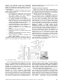
recorder. The instrument creates the temperatures difference graph versus time of the reference and tested sample. By analysing the obtained graph the user can determines most important thermodynamics parameters of the tested sample. With regard to the instrument’s purpose the user was defines adequate requirements. The instrument should to has the following functions: two physical and one arithmetic channel for the real time temperatures measurement of the reference and tested sample and their difference, o o respectively, in the range of 0 C-1000 C, on-line and off-line monitoring possibilities, the storage possibility of the measured and administrative (time, date, and comments) data into ASCII file. During the on-line monitoring the user should to has available start and stop options of the recording data operation in the form of file, numeric representations of three channels instant temperatures values during on-line monitoring, numeric representation of the surface of a temperature difference curve in the recorded time period, possibility of sampling rate adjustments, zoom tool and cursors for navigation during off-line monitoring, portability of the instrument’s acquisition hardware and simple connection with PC, simple instrument handshake possibility and electronic user’s manual. In order to satisfy proposed temperature range the instrument’s hardware must uses the thermocouples as sensors. This will requires an extra function of open thermocouple detection for both sensors having in mind length of the thermocouples. Acquisition hardware arrangement Taking into account the user’s requirements, the acquisition hardware with K-type thermocouples is designed to be connected with personal computer. The central part of the acquisition hardware is the Microchip microcontroller PIC18F4550 with built in the USB periphery. Complete scheme of the system hardware is showed in Fig. 1. As shown in Fig. 1. communication between the acquisition hardware and PC is established via USB port of the PC or precisely by emulating RS232 serial interface over USB. The communication device class (CDC) specification defines many communication models including serial emulation. By using the relevant CDC built-in functions integrated in the MCU firmware and appropriate driver, virtual COM port has been formed. This is necessary because the LabView 7 Express software has not embedded functions for USB control transfer. Simultaneously, the power lines of the PC’s USB port serve as power supply lines of the acquisition hardware due to large current capacity of 500mA and stable voltage of 5V. In this way, the acquisition hardware becomes independent on the external power supply sources. Two buttons in the scheme serve for the microcontroller in-circuit serial programming (ICSP) on the base of stand-alone USB bootloader program. So, the engineer can easily upgrade firmware without need of disassembling the hardware and with CCS C compiler software support. The PIC18F455 is a high performance, enhanced flash USB microcontroller with flexible oscillator structure and many special microcontroller features. Fig.1. The hardware of the proposed system: acquisition hardware and PC The MCU has 32Kbytes flash program memory and can store up to 16384 single-word instructions. The data memory is implemented as static RAM divided into 8 complete banks for a total of 2048 bytes. The data EEPROM is a nonvolatile memory array, separated from the RAM and program memory, that is used for long-term storage of program data or constants. The MCU PIC18F4550 consists of some standard peripherals as a 10-bit 13-channels analog-to-digital converter, PWM, Enhanced USART, comparator module and four timers. The device has an 31 level deep hardware stack and multiple internal and external interrupt sources with priority levels for interrupts. A watchdog timer with its own on-chip RC oscillator serves for reliable operation of the device. As can be seen in Fig. 1 the microcontroller is clocked by 20MHz crystal resonator. Precisely sampling time of 250ms is generated including RTC functionality of the 16-bit timer/counter TMR1 by adding an external LP watch oscillator. An overflow of the TMR1 register causes a TMR1 overflow interrupt (if enabled). The interrupt service routine can then perform the appropriate task. In order to satisfy wide temperature range demand, the thermocouples of K-type are adopted. This thermocouples type is comparatively inexpensive and accessible at the market. ANSI type-K (Iron-Constantan) and DIN (NiCr-Ni) thermocouples are composed of identical alloys and exhibit similar behavior. As can be seen from Fig. 1 the MAX6675 cold junction compensated K-thermocouple-to-digital PRZEGLĄD ELEKTROTECHNICZNY (Electrical Review), ISSN 0033-2097, R. 87 NR 12a/2011 157