1
converters (Maxim) are used for signal processing from a Ktype thermocouples. This converter resolves temperatures
o
o
to 0.25 C, allows readings as high as 1024 C and exhibits
thermocouple accuracy of 8 LSBs in temperatures range
o
o
o
from 0 C to 700 C. Over temperature of 700 C maximum
temperature error is about 17 LSBs. The thermocouple
should be attached as close to the chip as possible, so that
the cold junction and the chip (which is measuring the cold
junction temperature internally), are isothermal. The whole
assembly of the cold junction and the chip should be kept
away from sources of heat or thermal gradients of any kind,
perhaps inside an enclosure. The cold end (temperature of
MAX6675 chip) can only ranges from -20oC to 85oC. The
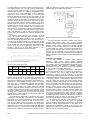
data is output in a 12-bit resolution, SPI compatible, readonly format, Fig. 2 and Table 1. Maximum conversion time
is 0.22 s. The MAX6675 includes a thermocouple failure
alarm that indicates if one or both thermocouple leads
become open. This preference is adequate applied in this
solution.
A complete serial interface read requires 16 clock
cycles. By forcing #CS low any conversion process
immediately stops. Read operation of the 16 output bits
occurs on the falling edge of the clock. The first bit, D15, is
a dummy sign bit and is always zero. Bits D14-D3 contain
the converted temperature in the order of MSB to LSB. Bit
D2 is normally low and goes high when the thermocouple
input is open. D1 is low to provide a device ID for the
MAX6675 and bit D0 is three-state. Initiation a new
conversion process starts by forcing #CS high.
Fig.2. SPI interface protocol of MAX6675
Table 1. Format of serial data output
Bit
Dummy 12-Bit Temperature
Sign Bit
Reading
Ord.
15
14
...
3
No.
0
MSB
LSB
Ther.
Input
2
Dev
ID.
1
State
0
Three
State
0
The Xbee-PRO RF modules (MaxStream) are used for
wireless connection [9] of the acquisition hardware with
other remote PC’s GUI. It allows the possibility of the real
time process monitoring and recording in the isolated room,
especially for demonstrative student’s lessons. As can be
seen from Fig. 1, communication between the PIC MCU
and Xbee-PRO RF module is established via serial data
interface of the module (3.3V CMOS UART–5V tolerant)
and the configured USART periphery of the PIC MCU. The
modules operate within the ZigBee protocol [9] and support
the unique needs of low-cost, low-power wireless sensor
networks. The modules require minimal power and provide
reliable delivery of data between remote devices within the
ISM 2.4 GHz frequency band.
RF modules have been easily configured by free X-CTU
configuration software, first as Coordinator and second as
End device at the point-to-point topology. Both short 16-bits
addresses have been matched as well as the baud rate,
also. The RF module conforms to the 802.15.4 specification
and supports both short 16-bit addresses and long 64-bit
addresses. Every one RF module is equiped with half-wave
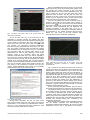
dipole antenna. Fig. 3. shows simple serial communication
betwen the RF module configured as End device and PC’s
158
COM port. External 5V power supply must be provided for
module supply and for MAX232 converter.
Fig.3. RF module connected with PC COM port as END device
The microcontroller’s firmware is written using CCS C
compiler IDE version 4.057. The program includes
procedures of the microcontroller’s peripherals initialization,
interrupt service routine, one-wire and specific two-wire
protocol for communication with sensors and USB CDC API
for virtual COM port creating. The system firmware starts or
stops program execution after received appropriate string
from the PC. By comparison the received string with the
adopted start and stop string constants within the interrupt
service routine the microcontroller resolves appropriate PC
request.
Graphical user interface
The user software is realised under Windows
operating system which ensure quality graphical
environment, multitasking and interaction between graphical
user interface objects and appropriated subroutines (eventdriven principle). The LabView software (National
Instruments-USA) [8], as leader in virtual instrumentations
domain, is used to realization our project.
LabView is a graphical programming development
environment based on the G programming language for
data acquisition and control, data analysis and data
presentation. LabView gives the flexibility of a powerful
programming language without the associated difficulty and
complexity because its graphical programming methodology
is inherently intuitive to programmers. With LabView the
user can control own system and present results through
interactive graphical front panels. On the front panel user
places the controls and data displays for own system by
choosing objects from the controls palette including numeric
displays, meters, gauges, LEDs, charts, graphs and more.
To program, programmer constructs the block diagram by
choosing objects (icons) from the functions palette and
connect them with wires to pass data from one block to the
next. These blocks range from simple arithmetic functions,
to advanced acquisition and analysis routines, to network
and file I/O operations. Therefore, LabView uses a dataflow
programming model, so called G, that frees programmer
from the linear architecture of text-based languages.
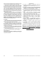
The realized GUI at on-line mode is shown in Fig. 4.
Two of three real time waveform charts are physical
channels while the last temperature difference waveform is
arithmetic channel. Digital indicators on the charts show
instantaneous temperatures values of all channels. The
front panel is divided in two parts which may be selected by
ON-LINE and OFF-LINE tab controls.
PRZEGLĄD ELEKTROTECHNICZNY (Electrical Review), ISSN 0033-2097, R. 87 NR 12a/2011