1
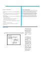
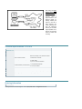
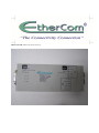
Configuration Examples There are two-position switches on the front surface (adjacent to RJ45 ports). These are the Normal or Crossover wiring polarity switches for each port and are labeled with wiring symbols on the top surface. Normal/Crossover The Crossover position enables use with reversed polarity wiring. The Normal position is for standard wiring pin-outs. Refer to the User’s Manual for pin-out descriptions. LEDs: Summary The ETP1010 has 14 LEDs. There is one LED per transceiver for each of the following: SQE Indicates SQE switch is on. Should be off during normal operation. TXD Indicates device is transmitting, should be on during normal operation. COL Indicates presence of collisions. Normally off during “clear” transmission periods. Will clear when collisions stop. PWR Indicates transceiver is properly receiving power from the network device to which it is connected through AUI port. Normally on. There are two LEDs (one per RJ45 port) for each of the following: REC Indicates that the port is receiving. Only one of the two ports should have the receive LED on during reception; the other should be off. LINK Indicates that a proper 10BaseT link has been established at the port. The active port’s Link LED should be the only one on during normal operation. If both LEDs are off, the transceiver is unable to establish a link at either port. The Link LED on the active or enabled port should be on if all connections have been made properly, if the cable is intact, and if the device on the other end of the cable is operational. Enab Indicates that the port is the one in use. Only one of the ports should on be in at any given time. During “hunt” periods both LEDs could appear to be on due to the rapid switching occurring as the transceiver searches for valid data. Pol Indicates that the connection being made has the wrong polarity. Needs rewiring or use of crossover switch. Should normally be off. Jab Indicates there is jabber on the line. Should normally be off at both ports. The configuration examples shown on the next page provide clarification on the proper ways to connect the ETP1010 in the network while illustrating the backup benefits of the redundancy port. Figures 1, 2, 3, 4, 5, 6, 7, 8 and 9 show the different ways that an ETP1010 can be configured correctly in a network. The shaded boxes designate the ETP1010 transceiver, and each is shown with two sets of twisted pair wiring connected to the RJ45 ports. Figures 4, 7, 8 and 9 include twisted pair connections from the ETP1010 transceivers directly to the RJ45 ports of 10BaseT hubs. Some of the configurations include connections at the other end of the twisted pairs to other ETP1010 devices, which in turn are connected to hubs via the AUI port; this presumes AUI (female) ports at the hub. Standard 10BaseT single port transceivers are shown as unshaded boxes with single twisted pair cables connected. These configurations show a wide range of possibilities for connecting the ETP1010 and therefore achieve backup through redundancy. Figures 5 and 6 are shown as examples of improper connections. Both configurations include workstations or hubs that are not looped together. In the case of figure 5, the ETP1010 cannot perform as a hub or backbone to provide the linkage between the 3 stations. The 2 work stations on the right side of the illustration would have to be linked together through a common backbone or hub for the configuration to work. In the case of figure 6, the two hubs are similarly not looped together; they would need a common backbone (as in fig. 7) for the configuration to work. 1409 Fulton Place, Fremont, CA 94539, USA Tel: (510) 440 0242 [email protected]