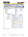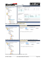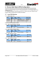
1
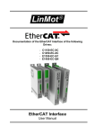
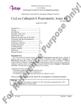
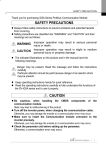
Documentation of the EtherCAT SoE Interface of the following Drives: • • • • C1150-SE-XC-0S/1S C1250-SE-XC-0S/1S E1250-SE-UC E1450-SE-QN-0S/1S _____________________________________________________________________________________________________ EtherCAT SoE Interface User Manual _____________________________________________________________________________________________________ SoE © 2015 NTI AG This work is protected by copyright. Under the copyright laws, this publication may not be reproduced or transmitted in any form, electronic or mechanical, including photocopying, recording, microfilm, storing in an information retrieval system, not even for didactical use, or translating, in whole or in part, without the prior written consent of NTI AG. LinMot® is a registered trademark of NTI AG. Note: The information in this documentation reflects the stage of development at the time of press and is therefore without obligation. NTI AG reserves itself the right to make changes at any time and without notice to reflect further technical advance or product improvement. Document version 6.4 / Whp, October 2015 Page 2/19 User Manual EtherCAT Interface NTI AG / LinMot SoE 1.SYSTEM OVERVIEW..................................................................................................................... 4 1.1REFERENCES........................................................................................................................................ 4 1.2CONNECTING IN AND OUT..................................................................................................................... 4 2.SETUP IN THE PLC......................................................................................................................... 5 2.1COPY DEVICE DESCRIPTION FILE........................................................................................................... 5 2.2SCAN THE ETHERCAT SLAVE DEVICES..................................................................................................... 5 3.PROCESS DATA OBJECT (PDO) CONFIGURATION.............................................................. 12 3.1 INPUT PDO MODULES...................................................................................................................... 12 3.1.1.Default Inputs: AT 1............................................................................................................ 12 3.1.2.Input: Following distance S-0-0189.................................................................................... 12 3.1.3.Input: DC bus voltage S-0-0380.......................................................................................... 12 3.1.4.Input: State Var P-1-2914.................................................................................................... 12 3.1.5.Input: X4 Inputs P-1-3205................................................................................................... 12 3.2OUTPUT PDO MODULES.................................................................................................................... 13 3.2.1.Default Outputs: MDT 1...................................................................................................... 13 3.2.2.Output: Velocity Command value S-0-0036......................................................................... 13 3.3TYPICAL STARTUP TELEGRAMS............................................................................................................. 13 4.ASYNCHRONOUS CONFIGURATION PROTOCOL SOE...................................................... 14 4.1COMMUNICATION PROFILE AREA(1000H-1FFFH).................................................................................. 14 4.2GENERIC LINMOT SOE PARAMETER MAPPING....................................................................................... 15 5.ETHERCAT SOE PARAMETERS................................................................................................ 16 5.1PARAMETERS...................................................................................................................................... 16 5.1.1.EtherCAT SoE/Dis-/Enable ............................................................................................... 16 5.1.2.EtherCAT SoE/Station Alias/Alias Address Source.............................................................. 16 5.1.3.EtherCAT SoE/Station Alias/Alias Address Parameter........................................................ 17 5.1.4.EtherCAT SoE/Station Alias/Alias Address Parameter Mask.............................................. 17 5.1.5.EtherCAT SoE/NC Configuration/Velocity Scale Numerator /Denominator........................17 5.1.6.EtherCAT SoE/Connection Timeout/Timeout Behavior....................................................... 17 6.CONNECTING TO THE ETHERCAT NETWORK................................................................... 18 6.1PIN ASSIGNMENT OF THE CONNECTORS X17-X18.................................................................................. 18 7.CONTACT ADDRESSES............................................................................................................... 19 NTI AG / LinMot User Manual EtherCAT Interface Page 3/19 SoE 1. System overview EtherCAT is the open real-time Ethernet network originally developed by Beckhoff. The LinMot act as Slave in this network and is implemented with the standard ASIC ET1100 from Beckhoff. With the SoE (Sercos over Ethernet) Protocol it is possible to use the Sercos functionality over the EtherCAT bus, the drive behaves as a Sercos drive. For further information on the EtherCAT fieldbus please visit: http://www.ethercat.org/ 1.1 References All user manuals are distributed with the LinMot-Talk software the newest versions can be downloaded from the LinMot homepage in the download section. Ref 1 2 Title Source User Manual Motion Control SW LinMot Drive Configuration over Fieldbus Interfaces SG5 www.linmot.com www.linmot.com 1.2 Connecting In and Out In the EtherCAT the cabling is directed due topology support, so In and Out is different! The real time Ethernet RJ45 connector X17 is the input and the real time RJ45 connector X18 is the output. Page 4/19 User Manual EtherCAT Interface NTI AG / LinMot SoE 2. Setup in the PLC In the following steps the integration of a LinMot EtherCAT Sercos Servo Drive in the PLC is described. In the example a Beckhoff master PLC is used. The easiest way is the online configuration when the device is connected to the EtherCAT network. 2.1 Copy Device Description File The LinMot Servo Drive is described with *.xml device description file distributed with the LinMot-Talk software. This file is only used when offline configuration is desired. Copy this file to PLC so it can access it. Example Source path of EtherCAT Device description file: C:\Programme\LinMot\LinMot-Talk 6.2 Build 20140915\Firmware\Interfaces\EtherCAT\XML\ NTIL_SoE_Servos_V1_2.xml Example Destination path of EtherCAT Device description file: C:\TwinCAT\Io\EtherCAT\ NTIL_SoE_Servos_V1_2.xml (for TwinCAT version 2) C:\TwinCAT\3.1\Config\Io\EtherCAT NTIL_SoE_Servos_V1_2.xml (for TwinCAT version 3) If this is done the PLC should recognize the corresponding LinMot drives on the EtherCAT fieldbus automatically. 2.2 Scan the EtherCAT slave devices Connect the EtherCAT LinMot CiA402 Servo Drive to the EtherCAT-Master and power on the signal supply. Then scan for the connected devices in the System Manager: NTI AG / LinMot User Manual EtherCAT Interface Page 5/19 SoE Scan for EtherCAT slave devices Page 6/19 User Manual EtherCAT Interface NTI AG / LinMot SoE With the question Add drives to NC-configuration select yes. These steps add the servo drive and its NC-axis to the project. NTI AG / LinMot User Manual EtherCAT Interface Page 7/19 SoE If the master also supports also the mapping Velocity command value it is strongly recommended to add this to MDT1 data. Add the Velocity command value by selecting it from the dictionary Page 8/19 User Manual EtherCAT Interface NTI AG / LinMot SoE MDT1 telegram with added Velocity command value Now the NC encoder has to be set to the correct value push the calulate button for this After this action the value should stand at this value (2^32). NTI AG / LinMot User Manual EtherCAT Interface Page 9/19 SoE Then the velocity output scale factor has to be set to 0.1 for correct operation Though the position controlling is done in the drive the controller output has to be set to 0. If this is forgotten, the behaviour could be noisy. To set these NC parameters they have to be downloaded. Page 10/19 User Manual EtherCAT Interface NTI AG / LinMot SoE Now the servo drive can be used with system manager NC functionality when started. NTI AG / LinMot User Manual EtherCAT Interface Page 11/19 SoE 3. Process Data Object (PDO) Configuration The cyclic process data is configured in the master and transmitted to the slave during startup. The default mapping is documented in the tables below. The inputs and outputs correspond to the PLC point of view. For a detailed description of the exchanged data and its meaning refer to [1]. For a detailed description of the PDO data refer to [1] or have a look at the TwinCAT demo program, which is included with the LinMot-Talk software. 3.1 Input PDO Modules 3.1.1. Default Inputs: AT 1 Index S-0-0016 S-0-0135 S-0-0051 Size [Byte] 6 2 4 Byte Offset 0 2 Name Data Type Variables RECORD Sdrive status word Uint16 Position feedback value Int32 1 Default input PDO mapping of 6 Bytes 3.1.2. Input: Following distance S-0-0189 Index S-0-0189 3.1.3. S-0-0380 Int32 Size [Byte] 4 Byte Name Offset 0 DC bus Voltage Data Type Int32 Input: State Var P-1-2914 Index P-1-2914 3.1.5. Data Type Input: DC bus voltage S-0-0380 Index 3.1.4. Size Byte Name [Byte] Offset 4 0 Following distance Size Byte Name [Byte] Offset 2 0 State Var Data Type Uint16 Input: X4 Inputs P-1-3205 Index P-1-3205 Page 12/19 Size Byte Name [Byte] Offset 2 0 X4 inputs Data Type Uint16 User Manual EtherCAT Interface NTI AG / LinMot SoE 3.2 Output PDO Modules 3.2.1. Default Outputs: MDT 1 Index Size Byte Name [Byte] Offset Data TypeS-00024 S-0-0024 6 Variables RECORD S-0-0134 2 0 Master control word Uint16 S-0-0047 4 2 Position command value Int32 Default output PDO mapping of 6 Bytes The default mapping could be extended with the following value. If the master also supports also the mapping Velocity command value it is strongly recommended to add this to MDT1 data. Index Size Byte Name Data [Byte] Offset TypeS-00024 S-0-0024 6 Variables RECORD S-0-0134 2 0 Master control word Uint16 S-0-0047 4 2 Position command value Int32 S-0-0036 4 6 Velocity command value Int32 3.2.2. Output: Velocity Command value S-0-0036 Index Size Byte Name Data Type [Byte] Offset S-0-0036 4 0 Velocity command value Int32 If the master supports also the Velocity command value, it is strongly recommended to at this part to the MDT 1 telegram. With this a much better dynamic could be reached. 3.3 Typical Startup Telegrams This figure shows the startup telegram list of LinMot SE servo drive NTI AG / LinMot User Manual EtherCAT Interface Page 13/19 SoE 4. Asynchronous Configuration Protocol SoE For configuration purpose (Parameter Handling) the standard Sercos over EtherCAT SoEProtocol is used. 4.1 Communication Profile Area(1000h-1FFFh) LinMot SoE Object Dictionary Page 14/19 User Manual EtherCAT Interface NTI AG / LinMot SoE 4.2 Generic LinMot SoE Parameter Mapping Apart from the above described parameters with the LinMot servo drives, there exists a generic parameter mapping of the LinMot parameters by UPID to the SoE parameter index by adding the UPID to 0x8000h. Reading and writing the value accesses the RAM value of the UPID. Writing to the default value accesses the ROM value of the UPID. NTI AG / LinMot User Manual EtherCAT Interface Page 15/19 SoE 5. EtherCAT SoE Parameters 5.1 Parameters The EtherCAT SoE Interface has an additional parameter tree branch (Parameters EtherCAT SoE), which can be configured with the distributed LinMot-Talk software. With these parameters, the EtherCAT interface can be enabled or disabled. The LinMot-Talk software can be downloaded from http://www.linmot.com under the section download, software & manuals. 5.1.1. EtherCAT SoE/Dis-/Enable With the Dis-/Enable parameter the LinMot Servo Drive can be run without the Ethernet EtherCAT Interface going online. So in a first step the system can be configured and run without any bus connection. ETHERCAT SoE\ Dis-/Enable Disable Servo Drive runs without ETHERCAT. Enable Servo Drive runs with ETHERCAT connection. IMPORTANT: If the ETHERCAT Interface is disabled, the integrated ETHERCAT-ASIC rests in reset state! No messages will be sent to other devices connected to the ETHERCAT-Network via the servo drive. 5.1.2. EtherCAT SoE/Station Alias/Alias Address Source With this parameter the station alias address source is defined. If a station alias address is defined in the ET1100 Eeprom (could be programmed from the master over the Network), this alias address is taken. ETHERCAT SoE/Station Alias/Alias Address Source None No station alias address is generated The ID switches defines the station alias address The lowest 2 bytes of the device MAC address RT MAC are used as station alias address The Station alias address parameter value Parameter defines the Alias Address The station alias address is defined by the Masked RT MAC and Parameter masked parameter ored with the RT MAC masked with the inverse mask ID Switches Page 16/19 User Manual EtherCAT Interface NTI AG / LinMot SoE 5.1.3. EtherCAT SoE/Station Alias/Alias Address Parameter Parameter value of the station alias address. 5.1.4. EtherCAT SoE/Station Alias/Alias Address Parameter Mask Mask value for the parameter value of the station alias address. 5.1.5. EtherCAT SoE/NC Configuration/Velocity Scale Numerator /Denominator This two parameters are taken to Scale the PDO Value of “Target velocity” (Index 0x60FF) to the Drive Resolution which is [1um/s]. The Scaling factor is Velocity Scale Numerator divided by Velocity Scale Denominator. For the Beckoff this factor is typically 1/60 -> Velocity Scale Numerator = 1 and Velocity Scale Denominator = 60. 5.1.6. EtherCAT SoE/Connection Timeout/Timeout Behavior With this parameter the drive behavior on an Connection timeout could be set. This parameter is also represented in the profile parameter with index 0x6007. ETHERCAT SoE\ Conection Timeout/Timeout Behavior Ignore Nothing happens if an IO timeout occurs. Error with Disable Voltage Error with Quick Stop Error with Go To Pos NTI AG / LinMot Drive goes to Error State and the Voltage is disabled immediately when the IO timeout occurs. Drive goes to Error State before the Voltage is disabled a Quick Stop is performed, when the IO timeout occurs. Drive goes to Error State before the Voltage is disabled a Go To Position is performed, when the IO timeout occurs. User Manual EtherCAT Interface Page 17/19 SoE 6. Connecting to the EtherCAT Network 6.1 Pin Assignment of the Connectors X17-X18 The ETHERCAT connector is a standard RJ45 female connector with a pin assignment as defined by EIA/TIA T568B: Page 18/19 X17 – X18 ETHERCAT Connector Pin Wire color code 1 WHT/ORG 2 ORG 3 WHT/GRN 4 BLU 5 WHT/BLU 6 GRN 7 WHT/BRN 8 BRN case - RJ-45 Use standard patch cables (twisted pair, S/UTP, AWG26) for wiring. This type of cable is usually referred to as a “Cat5e-Cable”. User Manual EtherCAT Interface NTI AG / LinMot SoE 7. Contact Addresses --------------------------------------------------------------------------------------------------------------------------SWITZERLAND NTI AG / LinMot Haerdlistr. 15 CH-8957 Spreitenbach Sales and Administration: +41-(0)56-419 91 91 [email protected] Tech. Support: +41-(0)56-544 71 00 [email protected] Tech. Support (Skype) : skype:support.linmot Fax: Web: +41-(0)56-419 91 92 http://www.linmot.com -------------------------------------------------------------------------------------------------------------------------USA LinMot, Inc. 204 E Morrissey Dr. Elkhorn, WI 53121 Sales and Administration: 877-546-3270 262-743-2555 Tech. Support: 877-804-0718 262-743-1284 Fax: 800-463-8708 262-723-6688 E-Mail: Web: [email protected] http://www.linmot-usa.com -------------------------------------------------------------------------------------------------------------------------Please visit http://www.linmot.com to find the distributor nearest to you. Smart solutions are… NTI AG / LinMot User Manual EtherCAT Interface Page 19/19