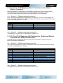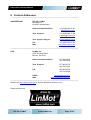
1
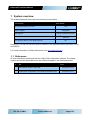
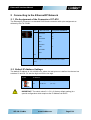
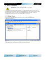
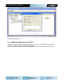
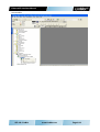
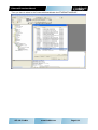
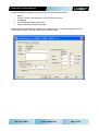
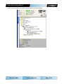
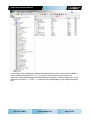
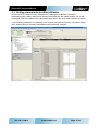
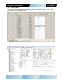
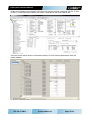
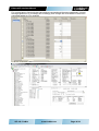
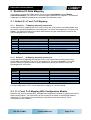
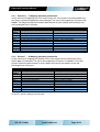
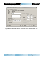
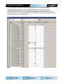
Ethernet/IP Interface User Manual This document applies to the following drives: E1250-IP-xx C1250-IP-xx E1450-IP-xx (with Ethernet/IP Interface SW installed) Ethernet/IP Interface Manual © 2012 NTI AG This work is protected by copyright. Under the copyright laws, this publication may not be reproduced or transmitted in any form, electronic or mechanical, including photocopying, recording, microfilm, storing in an information retrieval system, not even for didactical use, or translating, in whole or in part, without the prior written consent of NTI AG. LinMot® is a registered trademark of NTI AG. Note: The information in this documentation reflects the stage of development at the time of press and is therefore without obligation. NTI AG reserves itself the right to make changes at any time and without notice to reflect further technical advance or product improvement. Document version 4.3.2 / Whp, ka, August 2014 NTI AG / LinMot www.LinMot.com Page 2/32 Ethernet/IP Interface Manual 1 System overview ............................................................................................................ 4 1.1 2 3 4 Connecting to the Ethernet/IP Network ........................................................................... 5 2.1 Pin Assignment of the Connectors X17-X18 ............................................................ 5 2.2 Default IP Address Settings ..................................................................................... 5 Setup in the PLC ............................................................................................................ 6 3.1 RSLinx Classic ........................................................................................................ 6 3.2 LinMot Configuration in the PLC .............................................................................. 7 3.3 Getting started with the Watch Window ..................................................................17 3.3.1 Control Word ...................................................................................................18 3.3.2 Motion Command Interface .............................................................................21 Ethernet/IP Parameters .................................................................................................25 4.1 5 References.............................................................................................................. 4 Parameters ............................................................................................................25 Realtime IO Data Mapping ............................................................................................27 5.1 Default O ->T and T->O Mapping ...........................................................................27 5.1.1 Default O → T Mapping Assembly Instance 32 ...............................................27 5.1.2 Default T → O Mapping Assembly Instance 16 ...............................................27 5.2 O ->T and T->O Mapping With Configuration Module .............................................27 5.2.1 Default O → T Mapping Assembly Instance 40 ...............................................28 5.2.2 Default T → O Mapping Assembly Instance 24 ...............................................28 5.2.3 PLC Setup of Mapping with Configuration Module ..........................................29 5.2.4 Example of reading Parameter RAM value with Configuration Module ............30 5.3 O ->T and T->O Mapping without Controlword and without Motion Command .......31 5.3.1 Default O → T Mapping Assembly Instance 8 .................................................31 5.3.2 Default T → O Mapping Assembly Instance 24 ...............................................31 5.4 O->T and T->O Mapping with Configuration Module and Motion Command but without Controlword ..........................................................................................................31 6 5.4.1 Default O → T Mapping Assembly Instance 27 ...............................................31 5.4.2 Default T → O Mapping Assembly Instance 24 ...............................................31 Contact Addresses ........................................................................................................32 NTI AG / LinMot www.LinMot.com Page 3/32 Ethernet/IP Interface Manual 1 System overview The LinMot Ethernet/IP drives have the following functionalities: Device Property Value / Remark Minimal Ethernet/IP cycle time 1 ms DHCP -Support Supported EDS Support Not yet supported from AB For 3rd parties not supported from AB IEEE1588 (CIP-Synch) DLR Support (Device Level Ring Protocol) No Ethernet/IP is a real time Ethernet protocol based on the standard Ethernet protocols TCP/IP and UDP/IP. For further information on Ethernet/IP please visit: http://www.odva.org 1.1 References All user manuals are distributed with the LinMot-Talk configuration software. The newest version can also be downloaded from the LinMot homepage in the download section. Ref Title 1 User Manual Motion Control SW www.linmot.com 2 LinMot Drive Configuration over Fieldbus Interfaces SG5 www.linmot.com NTI AG / LinMot Source www.LinMot.com Page 4/32 Ethernet/IP Interface Manual 2 Connecting to the Ethernet/IP Network 2.1 Pin Assignment of the Connectors X17-X18 The Ethernet/IP connector is a standard RJ45 female connector with a pin assignment as defined by EIA/TIA T568B: X17 – X18 RealTime Ethernet Connector Pin RJ-45 Wire color code Assignment 100BASE-TX 1 WHT/ORG Rx+ 2 ORG Rx- 3 WHT/GRN Tx+ 4 BLU - 5 WHT/BLU - 6 GRN Tx- 7 WHT/BRN - 8 BRN - case - - Use standard patch cables (twisted pair, S/UTP, AWG26) for wiring. This type of cable is usually referred to as a “Cat5eCable”. 2.2 Default IP Address Settings The default IP address is 192.168.001.xxx, where the last byte xxx is defined via the two hex switches S1 and S2. S1 sets the high and S2 the low digit. S1, S2: IP Selectors S1 Bus ID High (0h…Fh) S2 Bus ID Low (0h…Fh) IMPORTANT: The switch value S1 = S2 = 0 (factory default setting) is a special configuration which acquires the IP address via DHCP. NTI AG / LinMot www.LinMot.com Page 5/32 Ethernet/IP Interface Manual 3 Setup in the PLC IMPORTANT: Use only AB PLC firmware 18.0 or higher! The following steps describe the integration of a LinMot Ethehernet/IP drive in the PLC. In the example an Allen Bradley master PLC is used. RSLinx tool can only be used to see if the device is on the network and under which IP-address it can be accessed. The whole configuration is done in the PLC, which is described in chapter 3.2. 3.1 RSLinx Classic In the RSLinx the LinMot device should occur under the defined IP address as “Unrecognized Device” LinMot device with the IP address 192.168.1.89 in the RSLinx tool. NTI AG / LinMot www.LinMot.com Page 6/32 Ethernet/IP Interface Manual LinMot device properties 3.2 LinMot Configuration in the PLC There are two possibilities to configure a LinMot in the PLC, one with the EDS-File and the other is to configure it as a Generic Ethernet Module. The LinMot can be configured in the I/O configuration section, in the Ethernet section as a NTI AG / LinMot www.LinMot.com Page 7/32 Ethernet/IP Interface Manual new module NTI AG / LinMot www.LinMot.com Page 8/32 Ethernet/IP Interface Manual Then you have to select in the Communications Module the ETHERNET-MODULE NTI AG / LinMot www.LinMot.com Page 9/32 Ethernet/IP Interface Manual Under the Module Properties you can define the module specific data: • • • • • Name Comm Format in the example a 16 bit Format is chosen! IP Address Input Assembly instance and size Output Assembly Instance and size Be careful when defining these parameters, because only a correct setting will run in the Ethernet/IP network. Only the name can be defined freely. NTI AG / LinMot www.LinMot.com Page 10/32 Ethernet/IP Interface Manual In the Connection tab of the Module Properties the desired cycle time is specified in the range between 1ms and 3200ms. Then the configuration/program can be downloaded and you can change to the online view. It is recommended to use Unicast Connection type, because there are no known problems with this type. NTI AG / LinMot www.LinMot.com Page 11/32 Ethernet/IP Interface Manual To configure the LinMot with the EDS File, the EDS-File must be downloaded into the configuration software for the PLC. In the RSLogix 5000 there is the EDS Hardware Installation Tool, which is used for the installation. It can be found in the Menu under Tools. Then you can click next until the Options window is shown. In this window Register an EDS file(s) has to be selected. NTI AG / LinMot www.LinMot.com Page 12/32 Ethernet/IP Interface Manual In the Registration window, “Register a directory of EDS files” has to be selected. The path of the directory is ../LinMot-TalkX.X BuildX/Firmware/Interfaces/EthernetIP/EDS. After this selection you can click next and finish the EDS Hardware Installation. When the EDS-Files are downloaded in the PLC configuration software, the LinMot can be configured in the I/O configuration section, in the Ethernet section as a new module. In the section “Module Type Vendor Filters” there is the Vendor “NTI Limited”, where the drive can be selected. NTI AG / LinMot www.LinMot.com Page 13/32 Ethernet/IP Interface Manual After creating a new module under Module Definition 'Change...' four communication types can be chosen. - As_0x28_0x18: Realtime IO with configuration module - As_0x20_0x10: Realtime IO without configuration module - As_0x08_0x18: Realtime IO with configuration module, but without the control word and without the Motion Command - As_0x27_0x18: Realtime IO with configuration module and with Motion Command but without the control word. This type can be used in parallel with the EasySteps application for example. The other module properties are configured same the generic Ethernet Module. For an other new Module, the EDS File download is not needed once more. NTI AG / LinMot www.LinMot.com Page 14/32 Ethernet/IP Interface Manual If all is set up correctly the LinMot module status should be running NTI AG / LinMot www.LinMot.com Page 15/32 Ethernet/IP Interface Manual In the LinMot-Talk configuration software the Ethernet/IP connection state can be watched under variables\Ethernet/IP:O ->T, T-> O config. If everything is set up correctly, the connection state should change to Established when powered on after a certain time. In this state both counters O → T and T → O should count up depending on the configured period time. NTI AG / LinMot www.LinMot.com Page 16/32 Ethernet/IP Interface Manual 3.3 Getting started with the Watch Window In this section the basics of the LinMot device handling are explained. Instead of programming the LinMot, data can be directly influenced with the watch window. So, for the next steps, map the modules input data and output data in the quick watch window as below. In the following examples it is assumed, that a motor has been configured, the power supply is on, and the drive is correctly embedded in the Ethernet/IP network. NTI AG / LinMot www.LinMot.com Page 17/32 Ethernet/IP Interface Manual 3.3.1 Control Word The Control Word is mapped to the output data word 0. If setting this value to 1 the “Switch On” bit (bit 0) of the control word is set This can also be monitored with the LinMot-Talk software. NTI AG / LinMot www.LinMot.com Page 18/32 Ethernet/IP Interface Manual Setting the control word to 2049 (0x0801) sets also the “Home” bit (Bit 11) in the Control Word. Wait until the input word 0 “State Var” has the value 2319 (0x090F) Main State 9 (Homing) Sub State 0x0F (Homing finished). NTI AG / LinMot www.LinMot.com Page 19/32 Ethernet/IP Interface Manual Then the Control Word can be set to 1 again, the drive will change to Main State 8 (Operation Enabled) Sub State 0xC0 (Homed and In Target Position), the corresponding input word 0 has the value 2240. NTI AG / LinMot www.LinMot.com Page 20/32 Ethernet/IP Interface Manual 3.3.2 Motion Command Interface The rest of the output data (O.data[1]..O.data[11]) is mapped to the “Motion Command Interface”. The first word (O.data[1]) is the motion command header, the rest (O.data[1]..O.data[11]) is the command specific motion parameter set. In the next example we will set up a “Predef VAI Go To Pos (020xh)” Motion Command. First we set the target position low word (O.data[2]) to 0 then the target position high word (O.data[3]) to 2 and the motion command header (O.data[1]) to 513 (0x0201). Press the “Read Command” button and you see the sent command. NTI AG / LinMot www.LinMot.com Page 21/32 Ethernet/IP Interface Manual We will use the same command to move back to 0mm. Change the target position high word to 0. Then change the count nibble in the motion command header to 0. NTI AG / LinMot www.LinMot.com Page 22/32 Ethernet/IP Interface Manual In the next example we are going to use the most common motion command “VAI Go To Pos (010xh)”. In this example we define the motion command in the control panel first. Then we put the same values in the watch window. First the motion parameters, then the motion header! NTI AG / LinMot www.LinMot.com Page 23/32 Ethernet/IP Interface Manual For moving back to 0mm with the same motion command and the same parameters, just set the target position to 0 (O.Data[2] and O.Data[3]) then change the count nibble in the motion command header to 2 for example. NTI AG / LinMot www.LinMot.com Page 24/32 Ethernet/IP Interface Manual 4 Ethernet/IP Parameters 4.1 Parameters The Ethernet/IP interface has an additional parameter tree branch (Parameters Ethernet/IP Intf), which can be configured with the distributed LinMot-Talk software. With these parameters, the Ethernet/IP communication parameters can be configured. The LinMot-Talk software can be downloaded from http://www.linmot.com under the section download, software & manuals. Ethernet/IP Intf\ Dis-/Enable With the Dis-/Enable parameter the LinMot drive can be run without the Ethernet Ethernet/IP interface going online. So in a first step the system can be configured and run without any bus connection. Ethernet/IP\ Dis-/Enable Disable The drive runs without Ethernet/IP. Enable The drive runs with Ethernet/IP connection. IMPORTANT: If the Ethernet/IP interface is disabled, the integrated Ethernet/IP switch is not powered! No messages will be sent to other devices connected to the Ethernet-Network via the LinMot drive. Ethernet/IP Intf\Ethernet Configuration\ IP Configuration Mode This parameter defines how the IP address is assigned. Ethernet/IP Intf\Ethernet Configuraton\ IP configuration Mode DHCP IP address is acquired via DHCP mechanism. Static by IP Configuration IP address is defined with parameters only. Static with switches S1 and S2 (DHCP) IP address is defined with parameters and the last byte is defined with the value of the switches S1 and S2. The default IP address setting is 192.168.001.xxx ( xxx stands for the value of the switches S1 and S2) IMPORTANT: The switch value S1 = 0 and S2 = 0 (factory default setting) defines acquiring the IP address via DHCP. NTI AG / LinMot www.LinMot.com Page 25/32 Ethernet/IP Interface Manual Ethernet/IP Intf\Ethernet Configuration\ IP Configuration In this section the parameters for the IP address netmask, default gateway and multicast IP address are located. Ethernet/IP Intf\Ethernet Configuration\ IP Configuration IP address 1st Byte Highest byte of IP address IP address 2nd Byte Mid high byte of IP address IP address 3rd Byte Mid low byte of IP address IP address 4th Byte Lowest byte of IP address Netmask 1st Byte Highest byte of Netmask Netmask 2nd Byte Mid high byte of Netmask Netmask 3rd Byte Mid low byte of Netmask Netmask 4th Byte Lowest byte of Netmask Default Gatway 1st Byte Highest byte of Default Gatway Default Gatway 2nd Byte Mid high byte of Default Gatway Default Gatway 3rd Byte Mid low byte of Default Gatway Default Gatway 4th Byte Lowest byte of Default Gatway NTI AG / LinMot www.LinMot.com Page 26/32 Ethernet/IP Interface Manual 5 Realtime IO Data Mapping If you want to control the LinMot device just over the Control Word and the Motion Command Interface it is sufficient to use the mapping described in chapter 5. The different mappings over different instances are selected in the assembly class. 5.1 Default O ->T and T->O Mapping 5.1.1 Default O → T Mapping Assembly Instance 32 In this real time IO mapping the 16 bit control word, the 16 bit motion command header and the motion command parameters are exchanged. The size of this mapping is 24 bytes or 12 words. The AB generic Ethernet module adds another 6 bytes (status and counts) so the real exchanged size is 30 bytes. Assembly Class Instance 32 Byte Description Offset 00h MC SW_ControlWord 02h MC SW_MotionCommandHeader 04h MC SW_MotionCommandPar Bytes 00..03 08h MC SW_MotionCommandPar Bytes 04..07 0Ch MC SW_MotionCommandPar Bytes 08..11 10h MC SW_MotionCommandPar Bytes 12..15 14h MC SW_MotionCommandPar Bytes 16..19 Size / Type UInt16 / Bit coded UInt16 / 12Bit Command 4Bit count nibble UInt32 / Command specific UInt32 / Command specific UInt32 / Command specific UInt32 / Command specific UInt32 / Command specific 5.1.2 Default T → O Mapping Assembly Instance 16 In this real time IO Mapping the StateVar for the main state machine and several other helpful data is exchanged. The size of this mapping is 18 bytes or 9 words. For the AB generic Ethernet module another 2 bytes (Status and counts) are added, so the real exchanged size is 20 bytes. Assembly Class Instance 16 Byte Description Offset 00h MC SW StateVar 02h MC SW StatusWord 04h MC SW WarnWord 06h MC SW DemandPosition 0Ah MC SW ActualPosition 0Eh MC SW DemandCurrent Size / Type UInt16 / coded state depending UInt16 / Bit coded UInt16 / Bit coded Int32 / Position [100nm] Int32 / Position [100nm] Int32 / Current [1mA] For the configuration in PLC of this data refer to chapter 3.2 of this manual. 5.2 O ->T and T->O Mapping With Configuration Module With this real time IO configuration, an additional configuration module is mapped into the IO data communication. The functionality of this module is the same for all different fieldbus interfaces. For this reason, the functionality is described in the document [2] “Drive Configuration over Fieldbus”. NTI AG / LinMot www.LinMot.com Page 27/32 Ethernet/IP Interface Manual 5.2.1 Default O → T Mapping Assembly Instance 40 In this real time IO Mapping the 16 bit control word, the 16 bit motion command header and the motion command parameters are exchanged. The size of this mapping is 32 bytes or 16 words. The AB generic Ethernet module adds another 6 bytes (Status and counts) so the real exchanged size is 38 bytes. Assembly Class Instance 40 Byte Description Offset 00h MC SW_ControlWord 02h MC SW_MotionCommandHeader 04h MC SW_MotionCommandPar Bytes 00..03 08h MC SW_MotionCommandPar Bytes 04..07 0Ch MC SW_MotionCommandPar Bytes 08..11 10h MC SW_MotionCommandPar Bytes 12..15 14h MC SW_MotionCommandPar Bytes 16..19 18h Cfg Module Control Word 1Ah Cfg Module Index/.. 2Ch Cfg Module Value/.. Size / Type UInt16 / Bit coded UInt16 / 12Bit Command 4Bit count nibble UInt32 / Command specific UInt32 / Command specific UInt32 / Command specific UInt32 / Command specific UInt32 / Command specific UInt16 UInt16 UInt32/SInt32 5.2.2 Default T → O Mapping Assembly Instance 24 In this real time IO mapping the StateVar for the main state machine and several other helpful data is exchanged. The size of this mapping is 26 bytes or 13 words. For the AB generic Ethernet module another 2 bytes (Status and counts) are added, so the real exchanged size is 28 bytes. Assembly Class Instance 24 Byte Description Offset 00h MC SW StateVar 02h MC SW StatusWord 04h MC SW WarnWord 06h MC SW DemandPosition 0Ah MC SW ActualPosition 0Eh MC SW DemandCurrent 12h Cfg Module Status Word 14h Cfg Module Index/.. 16h Cfg Module Value/.. Size / Type UInt16 / coded state depending UInt16 / Bit coded UInt16 / Bit coded Int32 / Position [100nm] Int32 / Position [100nm] Int32 / Current [1mA] UInt16 UInt16 UInt32/SInt32 In the PLC this is configured as followed: NTI AG / LinMot www.LinMot.com Page 28/32 Ethernet/IP Interface Manual 5.2.3 PLC Setup of Mapping with Configuration Module Configuration of LinMot axis with additional Configuration Module (4 word input and 4 word output direction). NTI AG / LinMot www.LinMot.com Page 29/32 Ethernet/IP Interface Manual 5.2.4 Example of reading Parameter RAM value with Configuration Module Reading RAM value (0x1101 = 4353; X_Axis1:O.Data[12]) P Gain Position Control Parameter Set A (UPID5026; X_Axis1:O.Data[13]) the result in this example is 15 (X_Axis1:I.Data[11] and X_Axis1:I.Data[12]). The data in the response is valid as soon the count nibble value in the response state (X_Axis1:I.Data[9]) changes to the same value as in the control Word (X_Axis1:O.Data[12]). NTI AG / LinMot www.LinMot.com Page 30/32 Ethernet/IP Interface Manual 5.3 O ->T and T->O Mapping without Controlword and without Motion Command With this Realtime IO configuration, it is possible to configure the Drive over the Fieldbus. This is described in the document [2] “Drive Configuration over Fieldbus”. But the Controlword and the MotionCommand would not mapped in this configuration. 5.3.1 Default O → T Mapping Assembly Instance 8 In this real time IO Mapping the Config Module is exchanged. The size of this mapping is 8 bytes or 4 words. The AB generic Ethernet module adds another 6 bytes (Status and counts) so the real exchanged size is 14 bytes. Assembly Class Instance 8 Byte Description Offset 00h Cfg Module Control Word 02h Cfg Module Index/.. 04h Cfg Module Value/.. Size / Type Uint16 Uint16 Uint32/Sint32 5.3.2 Default T → O Mapping Assembly Instance 24 This Mapping is the same like it is described in Chapter 5.2.2. 5.4 O->T and T->O Mapping with Configuration Module and Motion Command but without Controlword This Realtime IO configuration is like the configuration described in Chapter 5.3 but the Motion Command is mapped also. 5.4.1 Default O → T Mapping Assembly Instance 27 The size of this mapping is 27 bytes. The AB generic Ethernet module adds another 6 bytes so the real exchanged size is 33 bytes. Assembly Class Instance 8 Byte Description Offset 00h MC SW_MotionCommandHeader 02h MC SW_MotionCommandPar Bytes 00..03 06h MC SW_MotionCommandPar Bytes 04..07 0Ah MC SW_MotionCommandPar Bytes 08..11 0Eh MC SW_MotionCommandPar Bytes 12..15 12h MC SW_MotionCommandPar Bytes 16..19 16h Cfg Module Control Word 18h Cfg Module Index/.. 1Ah Cfg Module Value/.. Size / Type Uint16 / 12Bit Command 4Bit count nibble Uint32 / Command specific Uint32 / Command specific Uint32 / Command specific Uint32 / Command specific Uint32 / Command specific Uint16 Uint16 Uint32/Sint32 5.4.2 Default T → O Mapping Assembly Instance 24 This Mapping is the same like it is described in Chapter 5.2.2. NTI AG / LinMot www.LinMot.com Page 31/32 Ethernet/IP Interface Manual 6 Contact Addresses --------------------------------------------------------------------------------------------------------------------------SWITZERLAND NTI AG / LinMot Haerdlistr. 15 CH-8957 Spreitenbach Sales and Administration: +41-(0)56-419 91 91 [email protected] Tech. Support: +41-(0)56-544 71 00 [email protected] Tech. Support (Skype) : skype:support.linmot Fax: Web: +41-(0)56-419 91 92 http://www.linmot.com -------------------------------------------------------------------------------------------------------------------------USA LinMot, Inc. 5750 Townline Road Elkhorn, WI 53121 Sales and Administration: 877-546-3270 262-743-2555 Tech. Support: 877-804-0718 262-743-1284 Fax: 800-463-8708 262-723-6688 E-Mail: Web: [email protected] http://www.linmot-usa.com -------------------------------------------------------------------------------------------------------------------------Please visit http://www.linmot.com to find the distributor closest to you. Smart solutions are… NTI AG / LinMot www.LinMot.com Page 32/32