1
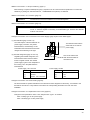
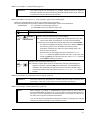
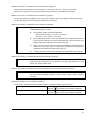
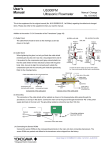
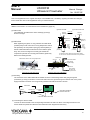
User’s Manual US300FM Ultrasonic Flowmeter Manual Change No. 10-007-2E This is the supplement for the original manual (No. IM 01G05B03-01E, 1st Edition) regarding the added and changed items. Please also refer to this supplement when you read the manual. Addition to the section “3.5.4 Connection of the Transducers” (page 18) : (1) Cable Finish (b) Junction box side (a) Main unit side Unit : mm (2) Cable Gland Perform soldering Shield line Brown (*) White 12±2 When tightening the gland, not only pull back the cable shield (meshed part) but also roll it out into a ring-shaped form and let Cable shield (meshed) it be pushed by the compression part (grey-colored plastic) so that the cable shield will have electrical contact with the gland Less than 10mm Thin lines (**) 10±3 7±2 Perform soldering 52±5 60±5 13±3 7±2 shown in the right. White Shield line Brown (*) 12±2 The cable finish should be done as the drawings (a) and (b) Less than 5mm Cable shield (meshed) Thin lines (**) body. Also, be sure to align the convexity part outside the compression part and the concavity part inside the gland body. (*) Finish the brown cables as well as white cables. (**) You do not connect the thin lines to any terminals. Refer to the drawings below. Gland body Cap nut Cable shield rolled out into a ring-shaped form Outer skin of the cable Cable shield (ringed-shape) Signal lines Rubber ring Compression part (convexity part outside) Compression part Gland body (concavity part inside) Components of the cable gland Outer wall of the main unit or junction box Cutaway view of the cable gland (3) Grounding The connection of the cable shield will be realized as shown in the drawing below after going through the procedures (1) and (2) in the above. Connect the main unit to the ground through the terminal “PE” of the power supply terminals in the main unit. The grounding resistance should be less than 100 ohm. Transducers Sensors Junction box Connection cable Main unit Grounding resistance less than 100 ohm GND Connection of the cable shield (4) Connecting the Sensor ROMs Connect the sensor ROMs to the corresponding terminals in the main unit when connecting transducers. The sensor ROMs are packed and affixed to the transducers when shipped from the factory. Manual Change for IM 01G05B03-01E 1st Edition : No.10-007-2E Yokogawa Electric Corporation Oct 29 2010-00 1/5 Addition to the section “3.1 Scope of Delivery” (page 11) : When ordering a couplant weatherproof type (by couplant code “R” in the transducer specification or model code USPA097), a package of “Shin-Etsu Silicone, 1 COMPONENT RTV (KE45T)” is delivered. Addition to the section “3.5.1 Location” (page 13) : Attention! The instrument must not be installed in a corrosive atmosphere. Addition to the section “3.5.1 Location” (page 13) : Attention! Use Submersible(IP68) type transducers when they are installed where condensation occurs. A Tokuchu request is necessary for Submersible type. However the diameter must be over 100 mm. Changes to the section “3.5.5 Connection to the Power Supply” (page 20) and some related pages : (1) Terminal Block (page 19 and 116) The outer shapes of the terminal block for The terminal names are the power supply connection, the printed terminal names, and the design on the PE N(-) same both for AC and DC L(+) power supply. board below the terminal block have been changed as the drawing in the right. KL3 (2) Terminal Assignment (page 21 and 116) This can be used as the Regarding the terminal assignment, the earth terminal instead of terminal names were revised as below the terminal “PE”. from the original manual. The needed power supply is given in the nameplate on the housing, not in the plate below the terminal block. Power supply, 100...240 VAC Terminal Connection PE N(-) L(+) Power supply, 24 VDC Terminal Earth Neutral Phase 100...240 VAC PE N(-) L(+) Connection (Earth) - DC + DC Changes to the section “3.6 Sensor ROM” (page 22) : The sensor ROMs are packed and affixed to the transducers when shipped from the factory, not inserted to the terminals in the main unit. They shall be connected to the corresponding terminals in the main unit when installation. Changes to the section “3.7 Replacement of the Fuse” (page 22) : Change the fuse specification “250V 1.25A, delayed action Type T” to as below. “250V 1A delay type” for AC power supply “250V 1.6A delay type” for DC power supply Manual Change for IM 01G05B03-01E 1st Edition : No.10-007-2E Oct 29 2010-00 2/5 Addition to the chapter “4. Getting Started” (page 23) : Attention! The current outputs may temporarily turn unstable during the power-on sequence (including re-starting after power failure) and parameter display / setting mode. Take care of your process not to be affected by this behavior. Addition and deletion to the section “4.1.1 Key Operations” (page 23) and related pages : Refer to the following table for the function of corresponding key operations. The correct explanations for these key operations in the related pages are also as the table below. Related pages: “4.1.1 Interruption of Power Supply” (page 27) “15.2 US300FM doesn’t react anymore” (page 106) Switches the background lighting ON/OFF. LIGHT BRK INIT RESET ENTER [Operation during the measurement or menu display] RESET: Press these three keys simultaneously to recover from an error. This has the same effect as restarting the unit. Data will not be affected. INIT (cold start): Press these three keys simultaneously and release ENTER first. After acknowledging the display of main menu, release (i) BRK key first and then (ii) C key. This will initialize the instrument. Most parameters and settings are reset to the factory default values. The memory will not be cleared. Note that when the data logging function is activated, the DELETE MEAS.VAL. display will appear instead of main menu. In this case, after releasing (i) BRK key first and then (ii) C key, select NO or YES and then press ENTER to finish the procedure. [Operation when powering the instrument on] BRK INIT INIT (coldstart): Pressing these two keys simultaneously and after acknowledging the display of main menu, release (i) BRK first and then (ii) C. This will initialize the instrument. Most parameters and settings are reset to the factory default values. The same procedure is required as above when the DELETE MEAS.VAL. display appears. Addition to the section “4.4.1 Interruption of Power Supply” (page 27) : Attention! The current outputs may temporarily turn unstable during the power-on sequence after power failure. Take care of your process not to be affected by this behavior. Addition to the chapter “5. Basic Measurement” (page 29) : Note! When changing any settings in "PARAMETER" program branch, be sure to also go through "MEASURING" program branch to the end where the measurement will start. In this case, you do not always have to fix the transducers on to the pipe, and thus you do not always need to get the actual flow measurement. If you shut off the power supply without taking this procedure, the settings to be changed would not be effective and keep the same settings as before. Manual Change for IM 01G05B03-01E 1st Edition : No.10-007-2E Oct 29 2010-00 3/5 Addition to the section “5.4 Selection of the Sound Path Factor” (page 34) : When the pipe outer diameter is more than 600mm, the sound path factor as “1” (one) is recommended. Otherwise, the measurement may become unstable when flow velocity or fluid temperature changed. Addition to the section “5.5.2 Mounting of the Transducers” (page 35) : The pipe wall thickness may slightly vary from part to part. Check it in advance by applying a wall thickness probe or some other ways and avoid mounting the transducers on such parts. Addition to the section “5.5.2 Mounting of the Transducers” (page 35) : Attention! Instructions for using “Acoustic couplant weatherproof type” (Shin-Etsu Silicone, 1 COMPONENT RTV) are as below. The operating condition of ambient temperature Before and during curing : 0 to +50°C / 32 to 122°F After curing : -40 to +180°C / -40 to 356°F When applying this couplant, cut the tip of attached nozzle to appropriate length and set it to the tube container. Also, remove matters like dust or oil on the surface to be applied. Otherwise, its adhesion force may become lower. When curing this couplant, keep the ambient and installation position temperature between 0 to +50°C (32 to 122°F). If not, the flow measurement may fail because of air bubbles formed inside the rubber before curing, etc. It usually takes one to three days for complete curing depending on the conditions. Addition to the section “5.5.2.2 Mounting with Fixtures and Chains” (page 36) : Attention! When using mounting fixtures, there may arise some air gap between the transducer surface and pipe wall because of any distortion of the pipe wall. Make sure to avoid having such air gap between them. Addition to the section “6.1 Selection of the Physical Quantity and of the Unit of Measurement” (page 39) : Attention! In case of mass flow, select “Other Medium” as a measured fluid. When “Other Medium” has been selected, US300FM requests to enter the density which is used to calculate mass flow. Changes to the section “7.2 Flow Totalizers” (page 43) : Two of the key operations have been changed as below, requiring pressing the keys “three times” . To reset the two flow totalizers to zero: OON three times when a totalizer is displayed. Press key To deactivate flow totalizing: Press key OOFF three times when a totalizer is displayed. Manual Change for IM 01G05B03-01E 1st Edition : No.10-007-2E Oct 29 2010-00 4/5 Addition to the section “14.5 Activation of a Pulse Output” (page 95) : Maximum pulse output rate is 2 pulse per second (+/-20%). Set the “Pulse Value” and the “Pulse Width” so that the actual maximum flow in the pipe is less than half the displayed value (“Max – Value”). Example: 3 The actual maximum flow 120m /h Pulse Value = 0.02m 3 Pulse Width = 150ms INFO: Max – Value 3 240.0m /h Attention! OON It is necessary to activate flow totalizers by pressing key to get the actual pulse output. Refer to the section 7.2 (page 43) for flow totalizers. Changes and addition to the terminal assignment for “Wiring” (page 116) : Terminal Description Name P2+ Current output (+, -) (when “Two current P2– outputs” is specified) P3+ P3– Frequency Output (+, –) (optional) Terminals for power supply are changed to “PE, N(-), L(+)” for both AC and DC power supply. Refer to page 2 of this document. Manual Change for IM 01G05B03-01E 1st Edition : No.10-007-2E Oct 29 2010-00 5/5