1
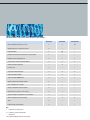
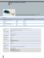
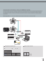
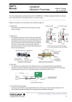
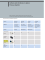
Software and interfaces at a glance:
These go together.
Which control software is suitable for which input device and how do their features differ?
The answer is easy to find in the clearly arranged direct comparison on this double-page spread.
The perfect match: supported interfaces and protocols
Software
Application
EC Control
Fan Control
Fan Clone
EC Controller
(page 20)
(page 22)
(page 23)
(page 30)
Service purpose
Service purpose
Manufacturing –
Stand-alone control
and stationary
and mobile operation
system monitoring
mobile operation, copy
device for refrigeration
and archive settings
and air-conditioning
technology
Hardware
Bluetooth adapter
(page 24)
USB adapter
(page 26)
Ethernet – RS485
interface converter
PC/laptop
PDA/smartphone
PDA/smartphone
•
•
•
•
•
•
•
(page 28)
RS485
MODBUS RTU
(page 30)
•
•
Performance features of the control software programs for PCs and PDAs
EC Control
Fan Control
EC Controller
Query and modify parameters of one fan
•
•
(•)
Modify parameters for group/entire system
•
–
–
Group view/floors
•
(•)
–
Detailed error history when software runs for long periods
•
–
–
Mapping a system layout/floor plan
•
–
–
Searching for a fan with an unknown address
•
•
•
Setting parameters graphically
–
•
–
E-mail on error
•
–
–
Support for multiple languages*
•
•
•
Support for RS485 ebmBUS
•
•
–
Support for RS485 MODBUS RTU
•
•
•
Support of Ethernet and multiple subnets
•
–
–
Duty cycle display on fan symbol
•
–
–
Display of information below fan symbol
•
–
–
Illustration of the system in a tree structure
•
–
–
Support of multiple configurations in one installation
•
–
–
German and English user manual (PDF)
•
•
•
Timer
•
–
–
Integrated help system (English)
•
–
–
Key:
• = Performance feature present
(•) = Possible in part/to a limited extent
– = Not present
* The supported languages differ for each product
Ethernet interface converter
RS485
This interface converter permits bi-directional connection of RS485 units and Ethernet-compatible
computers or laptops using the EC Control software (Art. No. 25714-2-0199).
Nominal data
Type
21488-1-0174 / 21489-1-0174 (UL version)
Nominal voltage and plug-in supply unit
Power supply
Current draw
Frequency
Ambient temperature (arranged in series)
Ambient temperature (not arranged in series)
Dimensions
VAC
VDC
mA
Hz
°C
°C
mm
100–240
12–48
85
50/60
0 to +50
0 to +60
105 x 75 x 22
Operating mode
RS485, two-wire mode without echo, automatic switchover between send and receive
Safety
Electrical isolation between Ethernet and RS485
Electrical isolation
Min. 500 V
Ethernet connection
8-pole RJ45 socket
10/100 Mbps autosensing
RS485 connection
9-pole SUB-D plug
Protocols used
– TCP
– Telnet
Status display
Via LEDs
– Green (left): power supply
– Green (right): data communication
– Red: fault
Housing
Plastic housing
Type of protection
IP 10
Installation
Standard rail mounting in accordance with DIN EN 50022-35
Delivery scope
– Interface converter
– Plug-in supply unit
– RS485 cable, D-Sub to screw terminal
– Network cable (crossover, Cat 5)
– German and English product description
28
Connecting the interface converter (Ethernet) – example of a fan with MODBUS RTU compatibility
The Ethernet interface converter serves to integrate bus-compatible EC fans into existing computer networks. This increases the spatial independence of
the control room and fans. Other than a power supply, all that is needed is a static IP address, which can be assigned easily using the EC Control software. Multiple Ethernet interface converters can be used without any problems. This allows, for example, larger systems to be divided up spatially to
reduce latencies.
Note for large systems: For 31 or more fans, an additional repeater is required, to which another 31 fans can be connected.
1
External sensor
Pressure sensor,
temperature sensor
Laptop
Power supply
Fans
MODBUS RTU RSA/RSB
Ethernet/TCP/IP
Interface converter
Ethernet
Art. No. 21488-1-0174
Art. No. 21489-1-0174
2
L2
KL1
L3
PE
L1
Aout
Din1
NC
Ain2 I
Ain1 I
NO
+20 V
+10 V
COM
GND
Ain2 U
GND
Din3
RSB
Ain1 U
Din2
KL2
RSA
KL3
2 Interface converter connection
PE
1 Example terminal assignment for fan
A
B
A = RSA
B = RSB
29