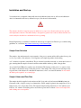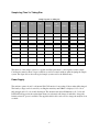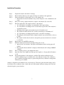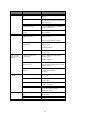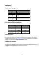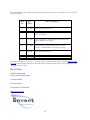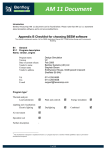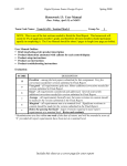
1
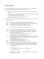
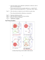
SULFUR SENTRY II Hydrogen Sulfide Analyzer Operator’s Manual Last Updated: July 03, 2015 Revision: 5 Envent Engineering Ltd. 7060 Bay E Farrell Road S.E. Calgary, Alberta, Canada, T2H 0T2, Tel: 403.253.4012 | Fax: 403.253.4016 | Email: [email protected], | Web: www.envent-eng.com For further information, or a copy of our most recent operating manual, please visit us at www.envent- eng.com. Envent Engineering Ltd. reserves the right to change product design and specifications at any time without prior notice All products carry a one year limited warranty from the date of start-up or 18 months from date of shipment, whichever occurs first, F.O.B. the factory, against defective parts or workmanship. Quick Start Guidelines Analyzer must be connected to no more than 15psi sample inlet pressure. The analyzer contains a critical orifice on the sample inlet bulkhead to achieve a flow of 2 into the sample chamber. The analyzer is not equipped with per-conditioning filtration for wet/dirty test sample. It is recommended that a minimum sample point selection should be a Genie Probe.Once a suitable sample point has been selected, connect to sample inlet lineon the analyzer. Use Menu centre button to scroll to mV. Once gas is flowing into the analyzer the mV reading will begin to drop. This will indicate that the analyzer is reading your sample. Important: Once the Mv start to drop, give the analyzer at least 15min to for the unit to stabilize. YOU WILL NOT SEE AN IMMEDIATE RESPNSE FROM THE ANALYZER AND IT MAY NOT DO A TAPE RUN FOR SEVERAL MINUTES AS THE ELECTRONICS CALCULATE A FIRST READING. This analyzer has been calibrated from 0-20ppm if your sample is higher please consult the factory.Select a suitable vent line that is away from the analyzer. Take analyzer out of bypass using bypass control Table of Contents Introduction ................................................................................................................................................... 1 Technical Specifications ............................................................................................................................... 1 Principle of Operation ................................................................................................................................... 2 Operation Interface ....................................................................................................................................... 4 Installation and Start-up ................................................................................................................................ 5 Sample Point Selection ........................................................................................................................... 5 Sample Volume and Flow Rate .............................................................................................................. 5 Sample Lag Time Vs. Tubing Size......................................................................................................... 6 Sample lag time vs. tubing size .............................................................................................................. 6 Power Supply ......................................................................................................................................... 6 Installation Procedure ................................................................................................................................... 7 Calibration Procedure ............................................................................................................................. 8 Tape Change Procedure.......................................................................................................................... 9 331 Analyzer Tape change procedure (Similar to sulfur sentry II) ........................................................ 9 Re-Zero Sensor Procedure.................................................................................................................... 10 Maintenance & Troubleshooting ................................................................................................................ 10 Monthly Checkup ................................................................................................................................. 10 Troubleshooting.................................................................................................................................... 11 Appendices.................................................................................................................................................. 13 Recommended Spare parts list ............................................................................................................. 13 H2S Concentration Conversion Factors ............................................................................................... 13 Computer Software............................................................................................................................... 13 Calibration Gas Humidifier .................................................................................................................. 13 Introduction The Sulfur Sentry H2S analyzer designed for temporary monitoring of H2S in natural gas pipelines. The analyzer will operate from an internal battery for over 12 hours. The H2S concentration is archived internally in non-volatile memory for later retrieval. The archive data can be exported to a spreadsheet for analysis and storage. Technical Specifications Sulfur Sentry Technical Specifications Specification Description Measurement method ASTM D4084 - 07 : Standard Test Method for Analysis of Hydrogen Sulfide in Gaseous Fuels (Lead Acetate Reaction Rate Method) Ambient 0-50 Deg C° (standard) consult factory for other requirements, 0 to 90% humidity (noncondensing) Temperature Power 12 vdc internal battery @ less than 3 watts for >12 hour operation, 120 vac wall charger and 12 volt vehicle charge cables included Output Ranges Standard ranges are between 0-100 ppm Response time 20 sec to 90% of step change Accuracy 1.5% of reading Display 2x16 character LCD with back lighting, Menu is scrolled by internal button 1 Sample Inlet – Sample Vent 12 VDC Power Input Sulfur Sentry component locations Principle of Operation The Envent Engineering Ltd. Sulfur Sentry uses ASTM D4084-07: Standard Test Method for Analysis of Hydrogen Sulfide in Gaseous Fuels (Lead Acetate Reaction Rate Method). This method uses lead acetate impregnated paper, referred to by Envent Engineering Ltd. as ‘H2S sensing tape”. The H2S sensing tape reacts when in contact with hydrogen sulfide by the relationship shown below. This reaction is visibly evident by a brown stain directly on the H2S sensing tape. Considering this reaction, the electronics built into the Models 330 & 331 have been programmed to measure the rate of darkening over time which, in turn, gives the hydrogen sulfide concentration. 2O H 2 S + Pb(CH 3COO ) 2 H → PbS + 2CH 3 COOH 2 Sulfur Sentry principle of operation diagram The figure above shows a flow regulated, pressure regulated and filtered process sample gas passing through a membrane humidifier and into the sample chamber. (See the following figure) A window in the sample chamber allows the gas to come in contact with the sensing tape creating the brown stain. Sample chamber and parts 3 For concentration applications over 10 ppm there may be a restricting aperture behind the window. Various sizes of apertures match different measurement ranges. See the table below. Range Aperture Size PN 100 ppb – 10 ppm None N/A 10 ppm – 20 ppm 1/16’’ 330103 20 ppm – 50 ppm 1/32’’ 330102 More than 100 ppm Consult Factory 330101 Operation Interface The Sulfur Sentry is configured by using the push-buttons. Refer to table below. Button Description/Function Bypass Used to inhibit all analyzer alarms to a non-alarm state, and sets the analog 4-20 mA output to 2 mA. Scroll Right [→] Used to move the cursor to the right. Also used to SAVE configuration adjustments. Scroll Left [←] Used to move the cursor to the left. Also used to CANCEL configuration adjustments. Menu/Set Used to cycle through the menu options. Also used to increase numerical values when making configuration adjustments. 4 Installation and Start-up Your analyzer was configured, functionally tested and calibrated at the factory. All test and calibration data is documented in the factory calibration report. (See the end of this manual) The analyzer should be located in an area in which it is not exposed to vibration and excessive pressure and temperature variations. The Sulfur Sentry is designed for general area locations. Ensure that the area can be safely de-classified to non-hazardous before operating. Envent Engineering is available for installation and start-up, if required. See Envent’s pre-commissioning guidelines on our website (http://www.envent-eng.com/documents.php). Sample Point Selection The sample to the analyzer must be representative of the process stream and should be taken from a point as close as possible to the analyzer to avoid lag times and sample degradation in the tubing. A ¾” weldelet is required for installation. The probe must be installed vertically on a horizontal section of pipe ensuring that the sample is drawn from between the middle and the top third of the pipeline. An optional Genie GPR probe regulator may be included. The function of this probe is to ensure a clean dry sample to the analyzer and to reduce the pressure of the sample. The lower pressure will improve the response time of the analyzer. For installation instructions, refer to associated documents. Do not install the Genie probe regulator on a vertical pipe. Sample Volume and Flow Rate The sample should be supplied to the analyzer at 10-15 psig and at a flow between 100-200 cc/min (set flowmeter at 2.0). A bypass sweep is recommended to reduce sample lag time in the sample line if it is at high pressure or it is longer than 15 feet. The standard sample tubing material is 1/4” 316 stainless steel; however, 1/8” stainless steel tubing can be used if the response time is critical. Carbon steel sample line and/or fittings are not acceptable. 5 Sample Lag Time Vs. Tubing Size. Tube Tube Size Gauge ID (“) Sample lag time vs. tubing size ID Flow Flow Pressure (cm) Std. (cc/min) (SCFH) (PSIA) Lag Lag Time per Time per 100’ (min) 100’ (sec) (“) 3/8 20 0.319 0.810 5 2359 800 36.30 2178 3/8 20 0.319 0.810 5 2359 200 9.07 544 3/8 20 0.319 0.810 5 2359 50 2.27 136 1/4 20 0.181 0.459 5 2359 800 11.69 701 1/4 20 0.181 0.459 5 2359 200 2.92 175 1/4 20 0.181 0.459 5 2359 50 0.73 44 1/8 20 0.081 0.205 5 2359 800 2.34 140 1/8 20 0.081 0.205 5 2359 200 0.59 35 1/8 20 0.081 0.205 5 2359 50 0.15 9 The function of the sample system is to regulate and filter particulates or free liquids from the sample. Consideration must be taken of upset conditions as well as normal conditions when designing the sample system. The figure below shows the typical sample system used for the Sulfur Sentry. Power Supply The analyzer operates from 12 volt internal Gel-Cell batteries for more than 12 hours when fully charged. The battery voltage can be observed by scrolling the menu key until VBAT is displayed. 13.5 volts is fully charged and 11.5 volts is fully discharged. The analyzer fault led will illuminate at 11.5 volts and LOW BAT will appear in the current alarm menu. An automatic wall charger is included to charge the batteries when AC power is available. The supplied vehicle cable can be used to charge the analyzer from a vehicle. 6 Installation Procedure Step 1. Step 2. Step 3. Step 4. Step 5. Step 6. Step 7. Step 8. Step 9. Step 10. Unpack the analyzer and check for damage Ensure that the analyzer power supply and range are suitable for the application Select an installation location that is close to the sample point. • Ensure that the selected installation site provides adequate room for maintenance and repair Wire power, analog outputs and discrete outputs to the analyzer (See section D) Tube the sample inlet, and sample vent lines to the analyzer • 1/4” 316 stainless steel tubing is recommended for the sample tubing • 1/8” 316 stainless steel tubing can also be used if the response time of the analyzer is of particular concern • All fittings in the sample and vent lines must be 316 stainless steel • The vent line should be tubed in 3/8” stainless steel tubing to a maximum of 6’ • 1/2” 316 stainless steel tubing should be used for vent lines exceeding 6’ • The tubing should be installed with a slight downward slope and should be as short as possible • The sample vent line must be tubed to atmospheric pressure and cannot be connected to a flare line Ensure there is enough H2S sensing tape With the sample pressure turned off (sample inlet valve closed) • Apply power to the analyzer. The display will illuminate and the sensing tape will advance. • Press the menu button until mV is displayed. Check that the mV reading is 1000 mV ± 100 mV Turn on sample gas flow (open sample inlet valve) Open the sweep valve slightly and adjust pressure regulator to 15 psig and the flowmeter to 2.0 Allow twenty minutes for the analyzer to stabilize. The analyzer calibration can be verified if calibration gas is available (refer to the calibration section). If no calibration gas is available, the analyzer may be operated using the factory calibration settings until calibration gas is available. Analyzer configuration and calibration was set at the factory. The factory gain and alarm settings can be found in the factory calibration sheet, found at the end of this manual. Analyzer settings can be read and adjusted using the operator interface. 7 Calibration Procedure Ensure a suitable calibration gas and a clean stainless steel regulator with the correct CGA fitting is available. Check that the regulator is rated for calibration cylinder pressure. • • • • The recommended calibration gas is hydrogen sulfide in a balance of nitrogen certified and analyzed. Calibration gas concentration should be approximately 2/3 of the full scale range of the analyzer or at the alarm point of the facility to be monitored Check the expiry date on the calibration gas bottle before using The recommended Calibration gas supplier is Air Gas Note that the following instructions apply to analyzers with standard sample systems; however, the basic principles still apply. Step 1. Step 2. Step 3. Step 4. Press the bypass button and verify that the “Bypass” LED illuminates Ensure there is enough H2S sensing tape (See E.2.2 if tape requires changing) Push the “Menu/Set” button until “Mtr Run” is displayed Push the right arrow [ → ] to move the H2S sensing tape forward • Step 5. Step 6. • • • • Step 7. • • Step 8. Step 9. Step 10. Step 11. • Ensure there is white tape at the sensor block window Press the “Menu/Set” button until the mV reading is displayed (“### mV”) If the mV reading is 1000 ± 100 mV, proceed to the next step, otherwise: Ensure there is no brown stain on the sensing tape at the sensor block window Ensure the sample chamber is clean Re-zero the sensor block (See section E.2.1 {Start at Step 4}) Re-check that the mV reading is 1000 ± 100 mV Connect the calibration gas using the Calibration Gas Humidifier (see Appendix) Connect the short end into the calibration port of the analyzer, ensure arrow is pointing towards the analyzer Connect the long end into the calibration gas bottle Set the calibration gas pressure to 15 psig Allow the analyzer reading to stabilize (10 to 15 minutes) Press the “Menu/Set” button until the gain setting is displayed (“### Gain”) Adjust the gain setting such that the analyzer reads the correct concentration Calculate gain, calculation should be close to the factory calibration sheet (See end of this manual) CalGasConcentration Current Re ading × (CurrentGain ) = ( NewGain ) • Press the right [ → ] and/or left [ ← ] arrows until the cursor is underneath the number you wish to change 8 • • Step 12. • Step 13. Step 14. Step 15. Step 16. Adjust the number using the “Menu/Set” pushbutton (it will increase until ‘9’, then cycle back through to 0’) The new gain can be saved by pressing the right arrow [ → ] until “Saved” appears or discarded by pressing the left [ ← ] arrow until “Cancel” appears Allow the analyzer to complete two cycles with the new gain setting The reading should match the calibration gas concentration Disconnect calibration gas bottle Allow the analyzer to return to a no-alarm condition Remove the analyzer from bypass Calibration is complete! Tape Change Procedure 331 Analyzer Tape change procedure (Similar to sulfur sentry II) 9 Re-Zero Sensor Procedure Step 1. Step 2. Step 3. Step 4. • Step 5. Step 6. • • Step 7. Step 8. • Step 9. Step 10. Step 11. Press the bypass button and verify that the “Bypass” LED illuminates Ensure the sample/calibration gas flow is turned off Press the “Menu/Set” button until “Mtr Run” is displayed Push the right arrow [ → ] to move the H2S sensing tape forward Ensure there is white tape at the sensor block window Remove the sensor cover Press the small pushbutton on the sensor block located on the lower left side next to the wire connector The sensor block will implement a “re-zero” procedure, indicated by a lit, red LED When the “re-zero” procedure is complete the LED light will turn green Initiate another motor run (Step 3 & 4) Press the “Menu/Set” button until “### mV” is displayed Value should be between 900 & 1100 mV Step 8. Put on sensor cover Turn on sample/calibration gas flow Set the gas pressure to 15 psig Remove the analyzer from bypass Maintenance & Troubleshooting Monthly Checkup Your analyzer will provide reliable service with very little attention. If the analyzer is kept clean there should be no requirement to recalibrate from factory gain settings. However, regular check-up will ensure that the analyzer is operating to specifications. • • • Ensure that the tape take-up and feed reels are tight Ensure that the flow meters, and sample chamber tubing are free of liquid or particulate contamination. Check that the sample conditioning filters every tape change or when sample conditioning system is saturated with liquid. Replace the inlet filter as required. 10 Troubleshooting For other possible solutions, please visit the ‘Frequently Asked Questions’ section of our website, at www.envent-eng.com/H2SFAQ.php. Sulsur sentry II Troubleshooting recommendations: Problem Erratic H2S Readings Possible reasons Possible Solution a. Trigger slide not seated properly Ensure trigger slide is seated in the groove of the sample chamber. b. Pressure in building moving up and down from fan, exhaust or wind Eductor may be plugged or vent blocked. Check that all vent tubing and fittings are 316 stainless steel, sized 3/8" or larger. c. Sample vent either blocked or frozen Vent should be 3/8" or larger tubing on a downward slope. Possible heat trace required. d. Liquid carry over in sample conditioning system Sample conditioning system requires cleaning. Refer to Cleaning procedures. e. Regulator not maintaining 15 psig Pre-regulation to 50 psig of sample at sample point. Possible regulator requires repair or replacement of Hydrocarbon liquid carried over through the sample regulator. Heated regulator may be required. f. Analog Input 2 jumper removed Re-install jumper in Analog Input across (+ 4-20 & -4-20). g. Sensor block fault Re-zero Sensor block. Refer to Sensor Re-zero procedure. check for green status led on sensor block. h. Contaminants in sample chamber Clean sample chamber. Replace aperture and window if required. Clear grease from window. Envent no longer uses grease on the chamber window. Applies to earlier H2S analyzers. i. Contaminants in sample conditioning system Sample conditioning system requires cleaning. Refer to Cleaning procedures. Tape does not advance a. No tension on take up reel Check setscrew in take up reel collars. Check to see if manual advance is possible on tape. Continued on next page 11 Problem Tape breaking Slow Response Possible reasons Possible Solution a. High liquid content in sample gas Genie probe and additional filtration may be required. b. Feed wheel not spinning freely Dust and refuse build up between feed wheel and chassis. Requires removal and cleaning of chassis. c. Tape cover wheels pressing against tape. Tape cover wheel became warped. Needs to be flattened to not contact tape when on feed wheel bolt. d. Trigger slide not seated properly Ensure trigger slide is seated in groove of sample chamber a. Aperture in chamber not optimized for range Removal or change of aperture type required. Contact Envent tech support for ideal setting b. Liquid contamination in sample tubing Sample conditioning system requires cleaning. Refer to Cleaning procedures. Higher or Lower than expecting reading c. Sensor block in fault Re-zero Sensor block. Refer to Sensor Rezero procedure. a. Liquid contamination in sample tubing Sample conditioning system requires cleaning. Refer to Cleaning procedures. Fault light indicated Sensor Fault b. Sample vent either blocked or frozen Vent should be 3/8" or larger 316 stainless steel tubing on a downward slope. Possible heat trace required. c. Contaminants in sample chamber Sample conditioning system requires cleaning. Refer to cleaning procedures. a. Sensor Low fault Re-zero Sensor block. Refer to Sensor Rezero procedure. b. Sensor High fault Re-zero Sensor block. Refer to sensor rezero procedure. c. Low Tape Sensing tape requires change. Possible low tape sensor failure. d. Low pressure Pressure on outlet of regulator is lower then set point of pressure switch. (factory set to 10 psi) a. Sensor didn't zero on white tape. Re-zero Sensor block. Refer to Sensor Rezero procedure. b. Sensor Wire failure Wire or Sensor requires replacement. 12 Appendices Recommended Spare parts list Part # Qty Description 330079 2 Rear Window & Gasket 330138 6 5’ Lead Acetate Tape 330405 1 Set of 5 permeable membrane o-rings 330900 1 Tubing, cleaner, fittings maintenance kit 330087 2 Calibration gas humidifier H2S Concentration Conversion Factors Original Unit mg / m Multiply By 3 Final Unit 0.698 ppm ppm 0.0626 grain / 100 cf % 10 000 ppm Mole / kMole 1000 ppm Computer Software The software for the 330 & 331 allows the user to change the factory configuration. The software is available on the Envent website at www.envent-eng.com. Contact our technical support department for assistance. A separate instruction manual is included with the software. Calibration Gas Humidifier The Calibration Gas Humidifier is used for calibration of Sulfur Sentries and H2S analyzers that do not use humidifiers. This humidifier should be replaced every six months. 13 This document has been continuously improved and revised over time; see the table below for revision (rev) information. Rev Description Rev No. Rev Date 01 Sept. 2011 Updated range specifications 02 Oct. 2011 Included changes required for different humidifier, updated format of document 03 Nov. 2011 Created manual in booklet format, and synchronized with updated 330&331 user manual 04 Oct. 2012 Edited principle of operation figure, removed some reference to the humidifier from cleaning procedures 05 Jul 2015 Changed the manual layout. For further information, or a copy of our most recent operating manual, please visit us at www.enventeng.com. Envent Engineering Ltd. reserves the right to change product design and specifications at any time without prior notice Head Office 7060E Farrell Road SE Calgary, AB T2H 0T2 Canada T +1.403.253.4012 F +1.403.253.4016 CAN Toll Free 1.877.936.8368 [email protected] 14