1
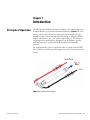
Mercuric Chloride Generator Instruction Manual Part Number 105648-00 27Jun2014 © 2007 Thermo Fisher Scientific Inc. All rights reserved. Specifications, terms and pricing are subject to change. Not all products are available in all countries. Please consult your local sales representative for details. Thermo Fisher Scientific Air Quality Instruments 27 Forge Parkway Franklin, MA 02038 1-508-520-0430 www.thermo.com/aqi WEEE Compliance This product is required to comply with the European Union’s Waste Electrical & Electronic Equipment (WEEE) Directive 2002/96/EC. It is marked with the following symbol: Thermo Fisher Scientific has contracted with one or more recycling/disposal companies in each EU Member State, and this product should be disposed of or recycled through them. Further information on Thermo Fisher Scientific’s compliance with these Directives, the recyclers in your country, and information on Thermo Fisher Scientific products which may assist the detection of substances subject to the RoHS Directive are available at: www.thermo.com/WEEERoHS. Thermo Fisher Scientific WEEE Compliance About This Manual This manual provides information about installing, running, maintaining, and servicing the Thermo Fisher Scientific (TFS) Oxidizer. It also contains important alerts to ensure safe operation and prevent equipment damage. The manual is organized into the following chapters and appendixes to provide direct access to specific operation and service information. Thermo Fisher Scientific ● Chapter 1 “Introduction” provides an overview of the product and describes the principle of operation. ● Chapter 2 “Installation” describes how to install the oxidizer into the 83i and the 83i GC, and how to modify the 82i for oxidizer retrofit. ● Chapter 3 “Operation” describes the associated menu-driven software and System Integrity calculations. ● Chapter 4 “Preventive Maintenance, Troubleshooting, and Servicing” presents safety alerts for technicians working on the instrument, preventive maintenance information, troubleshooting tips, and component replacement information. It also includes contact information for product support and technical information. ● Chapter 5 “Optional Equipment” describes the optional equipment that can be used with the oxidizer. ● Appendix A “Warranty” is a copy of the warranty statement. Mercuric Chloride Generator Instruction Manual i About This Manual Safety Safety and Equipment Damage Alerts Review the following information carefully before using the oxidizer. This manual provides specific information on how to operate the oxidizer, however if the oxidizer is used in a manner not specified by the manufacturer, the protection provided by the equipment may be impaired. This manual contains important information to alert you to potential safety hazards and risks of equipment damage. Refer to the following types of alerts you may see in this manual. Safety and Equipment Damage Alert Descriptions Alert Description DANGER A hazard is present that will result in death or serious personal injury if the warning is ignored. ▲ WARNING A hazard is present or an unsafe practice can result in serious personal injury if the warning is ignored. ▲ CAUTION The hazard or unsafe practice could result in minor to moderate personal injury if the warning is ignored. ▲ Equipment Damage The hazard or unsafe practice could result in property damage if the warning is ignored. ▲ Safety and Equipment Damage Alerts in this Manual Alert Description WARNING If the equipment is operated in a manner not specified by the manufacturer, the protection provided by the equipment may be impaired. ▲ It is crucial that there is an orifice on the outlet of the regulator, if there is not, a large, dangerous amount of chlorine will be released when the cylinder valve is opened. Ensure that the orifice is installed on the outlet of the regulator. The service procedures in this manual are restricted to qualified service personnel only. ▲ Equipment Damage ii Mercuric Chloride Generator Instruction Manual This adjustment should only be performed by an instrument service technician. ▲ Thermo Fisher Scientific About This Manual WEEE Symbol The following symbol and description identify the WEEE marking used on the instrument and in the associated documentation. Symbol Description Marking of electrical and electronic equipment which applies to electrical and electronic equipment falling under the Directive 2002/96/EC (WEEE) and the equipment that has been put on the market after 13 August 2005. ▲ Where to Get Help Service is available from exclusive distributors worldwide. Contact one of the phone numbers below for product support and technical information or visit us on the web at www.thermo.com/aqi. 1-866-282-0430 Toll Free 1-508-520-0430 International Thermo Fisher Scientific Mercuric Chloride Generator Instruction Manual iii Contents Thermo Fisher Scientific Chapter 1 Introduction ........................................................................................................ 1-1 Principle of Operation ........................................................................ 1-1 Component Description ..................................................................... 1-2 Oxidizer Weldment.......................................................................... 1-2 Heater .............................................................................................. 1-2 Heater Block .................................................................................... 1-2 Thermocouple.................................................................................. 1-2 Insulation ......................................................................................... 1-2 Oxidizer Enclosure ........................................................................... 1-2 Chapter 2 Installation ......................................................................................................... 2-1 Modify the 82i .................................................................................... 2-1 Update the 80i and 81i Firmware ....................................................... 2-4 Install the Oxidizer into the 83i .......................................................... 2-4 Install the CL2 Valve and Hg OX Valve ........................................... 2-4 Add Terminal Blocks 28, 29, and 30................................................ 2-6 Install the Heated Block and Orifice Assembly ................................. 2-8 Install the Converter Core .............................................................. 2-11 Install the Oxidizer ......................................................................... 2-13 Install the Oxidizer into the 83i GC.................................................. 2-15 Prepare the Probe ........................................................................... 2-15 Install New Valves .......................................................................... 2-17 Wire the Valves .............................................................................. 2-18 Remove 83i GC Fittings ................................................................ 2-18 Mount and Plumb the Converter and Oxidizer .............................. 2-19 Install Chlorine in Nitrogen Balance Cylinder ............................... 2-22 Verify Hydrator Connection .......................................................... 2-22 Chapter 3 Operation ............................................................................................................ 3-1 Overview ............................................................................................. 3-1 Hg Method ...................................................................................... 3-1 Zero Method.................................................................................... 3-1 Chlorine Cylinder Setting ................................................................... 3-2 Scheduling System Integrity Tests ....................................................... 3-2 Oxidation Schedule Menu ............................................................... 3-4 Next Time .................................................................................... 3-4 Period Days................................................................................... 3-5 Baseline Choice ............................................................................. 3-5 Baseline Duration Minutes............................................................ 3-5 Mercuric Chloride Generator Instruction Manual v Chlorine Duration Minutes .......................................................... 3-6 Post Condition Minutes ................................................................ 3-6 Total Run Time Minutes .............................................................. 3-6 Calculations ........................................................................................ 3-7 Chlorine Dilution Factor ................................................................. 3-7 System Integrity Calculation ............................................................ 3-7 vi Chapter 4 Preventive Maintenance, Troubleshooting, and Servicing ...................... 4-1 Safety Precautions ............................................................................... 4-1 Preventive Maintenance ...................................................................... 4-1 Chlorine Handling ........................................................................... 4-1 Troubleshooting.................................................................................. 4-2 Chlorine Flow .................................................................................. 4-2 Cold Spots ....................................................................................... 4-2 Teflon Tube Melting or Softening ................................................... 4-2 Leaks ................................................................................................ 4-2 Check Position of 81i Check Valve .................................................. 4-3 Baseline Not Flat.............................................................................. 4-3 Low Total Values During Chlorine Duration Step ........................... 4-3 Sample Values Read High After System Integrity Test ..................... 4-3 Servicing ............................................................................................. 4-3 Valve 83i GC Replacement .............................................................. 4-3 Chlorine Tank Replacement ............................................................ 4-3 Thermocouple Replacement............................................................. 4-4 Heater Cartridge Replacement ......................................................... 4-4 Service Locations ................................................................................. 4-4 Chapter 5 Optional Equipment........................................................................................... 5-1 Chlorine Detector ............................................................................... 5-1 Saf-T-Net System ............................................................................. 5-1 Appendix A Warranty............................................................................................................. A-1 Mercuric Chloride Generator Instruction Manual Thermo Fisher Scientific Figures Figure 1–1. Oxidizer Flow Diagram .................................................................... 1-1 Figure 1–2. Oxidizer Components ....................................................................... 1-2 Figure 2–1. Oxidizer Kit Wiring Diagram............................................................ 2-3 Figure 2–2. Installing the CL2 Valve, Hg OX Valve and Wiring Harnesses ........ 2-5 Figure 2–3. Plumbing the CL2 Valve and OX Valve............................................. 2-6 Figure 2–4. Adding New Terminal Blocks .......................................................... 2-7 Figure 2–5. Original 83i Configuration ............................................................... 2-9 Figure 2–6. Installing New Clam Shell ............................................................. 2-10 Figure 2–7. Installing New Orifice Assembly................................................... 2-11 Figure 2–8. Installing the Converter Core ........................................................ 2-12 Figure 2–9. Installing the Oxidizer .................................................................... 2-14 Figure 2–10. Model 83i GC Oxidizer Configuration ......................................... 2-16 Figure 2–11. Installing New Valves ................................................................. 2-18 Figure 2–12. Removing Fittings from 83i GC.................................................... 2-19 Figure 2–13. Mounting the Oxidizer Assembly ................................................ 2-20 Figure 3–1. System Integrity Test Performed with Hg Method ......................... 3-3 Figure 3–2. System Integrity Test Performed with the Zero Method ................ 3-3 Thermo Fisher Scientific Mercuric Chloride Generator Instruction Manual vii Tables Table 3–1. Chlorine Pressures and Expected Flows .......................................... 3-7 Thermo Fisher Scientific Mercuric Chloride Generator Instruction Manual ix Chapter 1 Introduction Principle of Operation The TFS Mercuric Chloride Generator (Oxidizer) uses a patented process by which chlorine gas is mixed with elemental mercury (Figure 1–1). This mixing is done a short distance from the probe injection point to help minimize contact of mercuric chloride with cold spots. Mercuric chloride (HgCl2) will adsorb to any "cool" surface (below 190° C). The chlorine is originated from a small cylinder (900 ppm Cl2 in N2 Balance), and the elemental mercury is originated from the Model 81i elemental Hg generator An oxidized mercury source is required in order to comply with 40 CFR Part 75 which states that a system integrity test needs to be performed once a week. Figure 1–1. Oxidizer Flow Diagram Thermo Fisher Scientific Mercuric Chloride Generator Instruction Manual 1-1 Introduction Component Description Component Description Oxidizer Weldment Heater Heater Block Thermocouple Insulation Oxidizer Enclosure Refer to Figure 1–2 to locate the oxidizer components. The oxidizer weldment acts as a reaction chamber that generates mercuric chloride when elemental mercury and chlorine are mixed together. The heater is a 240V, 300W firerod-style heater that heats the heater block and oxidizer weldment to approximately 400° C to facilitate the oxidation reaction. The heater block encloses the oxidizer weldment for even heating. The Type K thermocouple is used to measure the oxidizer temperature. The insulation surrounding the heater block helps maintain a uniform and constant temperature. The oxidizer enclosure is an aluminum box that contains the oxidizer components. 7”x 4” Heater Block Top Insulation Thermocouple 2”x 4” Oxidizer Weldment 7”x 2” (2) Heater Block Bottom 2”x 2” (2) Oxidizer Enclosure Heater Figure 1–2. Oxidizer Components 1-2 Mercuric Chloride Generator Instruction Manual Thermo Fisher Scientific Chapter 2 Installation This chapter applies to systems that do not have an oxidizer installed. In many cases, the oxidizer has already been installed into the equipment at the factory. If the oxidizer is already installed, go to Chapter 3. Installing the oxidizer includes the following recommendations and procedures: Modify the 82i ● “Modify the 82i” on page 2-1 ● “Update the 80i and 81i Firmware” on page 2-4 ● “Install the Oxidizer into the 83i” on page 2-4 ● “Install the Oxidizer into the 83i GC” on page 2-15 Use the following procedure to modify the 82i prior to installing the oxidizer. Refer to Figure 2–1. Equipment Required: Interface board, Rev D A1 and B cable assemblies 8-pin cable assembly Bracket assembly Electrical and Instructions for Oxidizer Kit 1. Power down the system and disconnect all power from the 82i and 80i, including sample pump. 2. Remove the 82i cover. 3. Remove connectors A1 and B from rear panel (Figure 2–1). Disconnect the associated wires from the relays and SSRs (make note of the wire color and the associated connector). Thermo Fisher Scientific Mercuric Chloride Generator Instruction Manual 2-1 Installation Modify the 82i 4. Replace existing 82i Interface board with the Rev D Interface board (label connections for reference). 5. Install the new A1 and B cable assemblies and reconnect the relay and SSR connections. 6. Disconnect the control wires from the SSRs that connect to the HEATERS connector on the Interface board and remove the cable assembly. 7. Connect the new 8-pin cable assembly to the HEATERS connector on the Interface board and connect the control wires to the SSRs (Figure 2–1). Note The colors are different on the new cable. The brown and blue wires connect to the SSR on the oxidizer relay plate (Figure 2–1). ▲ 8. Connect the blue wire from connector B to the AC side of the SSR. (Figure 2–1). 9. Install the bracket assembly (supplied with the kit) on the divider panel by snapping it into the bottom and securing it with screws at top (Figure 2–1). 10. Route the 2-pin connector from terminals 0 and 1 on the relay to the OXY RELAY connector (J12) on the interface board. 11. Depending on the power distribution board you have, plug the 3-pin connector to one of the spares on the bottom of the power distribution board, and replace the 82i fuse with a 3AG, 3 amp, 250V fuse. 12. Replace cover. 13. Plug in the power cords, turn on main 82i power switch, then turn the Model 80i on. 2-2 Mercuric Chloride Generator Instruction Manual Thermo Fisher Scientific REAR PANEL (INSIDE) COMMON ELECTRONICS (DISTRIBUTION BOARD) FLOOR PLATE LEGEND HINGED PANEL (OPEN) Installation Modify the 82i Figure 2–1. Oxidizer Kit Wiring Diagram Thermo Fisher Scientific Mercuric Chloride Generator Instruction Manual 2-3 Installation Update the 80i and 81i Firmware Update the 80i and 81i Firmware Install the Oxidizer into the 83i Install the CL2 Valve and Hg OX Valve You update firmware in the field via the serial port or over the Ethernet. This includes both the main processor firmware and the firmware in all low-level processors. Refer to the iPort manual for the firmware update procedure. Before beginning the following procedure to install the oxidizer into the 83i, perform the procedures described previously in “Modify the 82i” and “Update the 80i and 81i Firmware.” If the oxidizer is to be installed in an 83i GC, skip this procedure and go to “Install the Oxidizer into the 83i GC” in this chapter. Use the following procedure to install the CL2 valve and Hg OX (oxidizer) valve into the 83i. Equipment Required: 83i Retro Kit (105483-00) 1. Open up the 81i cover and ensure that the arrow on the check valve is pointing to the rear of the calibrator. This ensures that all of the 81i output is directed to the oxidizer. 2. Power down the system including sample pump and disconnect all power cables. 3. Shut down air supply at rack. 4. Remove probe covers and top valve cover. 5. Disconnect all valve wiring. 6. Install new wiring harnesses per drawing 105194. Note that the new harness is built for six valves. 7. Remove the valve from each end of the valve assembly (Figure 2–2). 8. Install the first (Hg OX) valve bracket (Figure 2–2). This bracket has the same hole pattern as the valve. Mount either of the 2-way valves 2-4 Mercuric Chloride Generator Instruction Manual Thermo Fisher Scientific Installation Install the Oxidizer into the 83i onto the top of this bracket, then remount the removed valve and new bracket. 42-inch Teflon Tube Hg OX Valve Install this valve bracket first Common 42-inch Teflon Tube Cl2 Valve (Green/Yellow) Hot Line Control (Green) (Various Colors) Valve Bracket Top View of Valve Remove Valve Slide bracket under valve Remove Valve Figure 2–2. Installing the CL2 Valve, Hg OX Valve and Wiring Harnesses 9. Mount the remaining bracket and the Cl2 valve to the mounting holes toward the rear of the probe (Figure 2–2). Remount old valve and new bracket. 10. Cut two lengths of 42-inch long PFA Teflon® tubes (Figure 2–2) and swage these two tubes to the outlet of both the new valves (terminal strip side / left). 11. Feed the other end of both tubes through an available orange grommet (these ends will be connected to the oxidizer later in this procedure). 12. Disconnect tube on right side of the lower front valve closest to pressure transducer, install the port connector and tee (Figure 2–3), then re-plumb the removed tube to the end of the tee. 13. Connect the middle of the tee to the inlet (right side) of the Hg OX valve with an 8-inch length of tubing (Figure 2–3). Thermo Fisher Scientific Mercuric Chloride Generator Instruction Manual 2-5 Installation Install the Oxidizer into the 83i Hg OX Valve Connect ¼-inch tubing to CL2 inlet Cl2 Valve 8-inch tubing to Hg OX valve Re-plumb removed tube Install port connector and tee Figure 2–3. Plumbing the CL2 Valve and OX Valve 14. Snake a ¼-inch Teflon line up through the probe strain relief and orange grommet, and connect to the inlet (right side) of the Cl2 valve (Figure 2–3). (The other end of this line will be connected to the Cl2 tank later.) Add Terminal Blocks 28, 29, and 30 Use the following procedure to add terminal blocks 28, 29, and 30. Equipment Required: 83i Retro Kit (105483-00) 1. Loosen the PE terminal block on the back of the terminal strip (farthest from the stack), and slide down the DIN rail to allow the insertion of two terminal block connectors between PE and number 1 (Figure 2–4). 2. Snap terminal blocks 29 and 30 (supplied) between PE and block 1. 2-6 Mercuric Chloride Generator Instruction Manual Thermo Fisher Scientific Installation Install the Oxidizer into the 83i 3. Slide the PE terminal block against the rest of the blocks and tighten the PE block. Add terminal blocks 29 and 30 here 25 26 27 21 22 23 Add terminal block 28 here Figure 2–4. Adding New Terminal Blocks Thermo Fisher Scientific Mercuric Chloride Generator Instruction Manual 2-7 Installation Install the Oxidizer into the 83i 4. Loosen the PE terminal block (Figure 2–4) on the front of the terminal strip (closest to the stack). 5. Slide down the PE, relay block, and terminal block number 24 so that terminal block 28 (supplied) can be inserted between terminal block number 20 and the relay block (Figure 2–4). 6. Slide blocks together tightly and tighten the PE block (Figure 2–4). 7. Complete valve wiring now that the new terminal blocks are installed (Figure 2–4). 8. Dress wiring and tubing so that the valve cover fits over the valves. Install the Heated Block and Orifice Assembly Use the following procedure to install the heated block and orifice assembly. Equipment Required: 83i Retro Kit (105483-00) 1. Remove both glass orifice blocks and associated fittings including the scrubber, Teflon line to converter, and dilution line into the orifice tee (Figure 2–5). 2. Remove the Teflon ¼ to ½-inch elbow from the converter tube closest to the stack. 2-8 Mercuric Chloride Generator Instruction Manual Thermo Fisher Scientific Installation Install the Oxidizer into the 83i Remove orifice blocks, orifices, scrubbers and assoc. plumbing Disconnect tubing from tees Disconnect and remove Teflon elbow Figure 2–5. Original 83i Configuration 3. Locate the bottom half of the oxidizer retrofit aluminum clam shell and the 19-inch piece of ¼-inch stainless steel tubing in the Retro Kit. 4. Using the same mounting holes that were used for the old orifice heater blocks, mount the new bottom clam shell to the existing aluminum block (Figure 2–6) so that the stainless-steel tube is inserted into the ¼inch cut out on the bottom of the new clam shell. 5. Attach the orange insulated Teflon end of this stainless-steel assembly to the bottom fitting of the dilution module (heated dilution air in). See Figure 2–6. 6. Install new stainless-steel orifice assembly into the new heated clam shell and connect plumbing from the orifice assembly to the dilution eductor (Figure 2–7). Thermo Fisher Scientific Mercuric Chloride Generator Instruction Manual 2-9 Installation Install the Oxidizer into the 83i 7. Screw the top of the new clam shell onto the bottom. See Figure 2–7 for completed assembly. To Bottom Fitting of Dilution Module New Bottom Clam Shell SS Tube Figure 2–6. Installing New Clam Shell 8. Connect the orange insulated Teflon assembly (connected to the orifice pre filter) to the top fitting (not vacuum) of the dilution module. This is the new diluted sample out line. 9. Connect the atmospheric dump to the fitting at the rear of the new clam shell assembly (pointing to the right). See Figure 2–7. 10. Connect the elemental sample line (umbilical 2) to the fitting at the center of the new clam shell assembly (pointing right). See Figure 2–7. 2-10 Mercuric Chloride Generator Instruction Manual Thermo Fisher Scientific Installation Install the Oxidizer into the 83i Total Orifice Pressure Elemental New Heated Calm Shell Bypass Dump New SS Orifice Assy Plumb Orifices Assy to Dilution Eductor Figure 2–7. Installing New Orifice Assembly Install the Converter Core Use the following procedure to install the converter core. Equipment Required: ½ to ¼-inch glass-coated, stainless-steel elbow ½ Teflon ferrules 1. Connect the ½ to ¼-inch glass-coated, stainless-steel elbow to the inlet of the converter (Figure 2–8). This fitting should use ½-inch, two-piece Teflon ferrules. 2. Connect orange insulated Teflon tube from center of new clam shell (Total line) to converter inlet elbow (Figure 2–8). Use two wrenches when tightening the converter inlet elbow –one to hold the elbow and the other to turn the nut. Note Any time the converter connections are disconnected, the chamber pressure should be checked after the system is restarted to ensure a leak-free connection. ▲ Thermo Fisher Scientific Mercuric Chloride Generator Instruction Manual 2-11 Installation Install the Oxidizer into the 83i Connect 1/2-1/4-inch Glass Coated SS Elbow Connect Orange Insulated Tube to Converter Inlet Elbow Figure 2–8. Installing the Converter Core 2-12 Mercuric Chloride Generator Instruction Manual Thermo Fisher Scientific Installation Install the Oxidizer into the 83i Install the Oxidizer Use the following procedure to install the oxidizer. Equipment Required: Drill Drill bit #7 (13/64-inch) (supplied) Glass-coated union (supplied) 1. Replace the elbow fittings on the venturi with a glass-coated tee (Figure 2–9). Reconnect line to venturi transducer. 2. Connect the orange insulated tube assembly to the center fitting of the oxidizer and connect the other end to the glass-coated venturi tee closest to oxidizer (Figure 2–9). Note There are two configurations of fast loop assemblies. One has the venturi and eductor fittings pointing down, the other has them off to the right side. Two different insulated tube assemblies have been provided to accommodate these two variations. Identify which tube assembly is correct for the specific probe. ▲ 3. Mark the locations of the four slotted holes on the oxidizer support bracket relative to the probe case (Figure 2–9). Thermo Fisher Scientific Mercuric Chloride Generator Instruction Manual 2-13 Installation Install the Oxidizer into the 83i Oxidizer Union Oxidizer Support Bracket Glass-coated Tee Figure 2–9. Installing the Oxidizer 4. Remove oxidizer bracket and drill clearance holes for a number 8 screw (Figure 2–9). (Mounting holes may be optional depending on probe orientations, such as horizontal orientation.) 5. Install oxidizer bracket to probe and reattach oxidizer insulated tube to venturi assembly (Figure 2–9). 6. Connect the 42-inch piece of Teflon tube (from the Cl2 and Hg OX valves) to either union on the oxidizer. Tubing should be cut and dressed to fit (Figure 2–9). 7. Snake the oxidizer heater wires up into the valve cover and terminate according to Figure 2–4 (drawing 105483-00). 8. Connect the oxidizer thermocouple to one of the spare thermocouple’s feeds-through in the umbilical. Ensure that the other end is connected to “Umbilical 2” in the 82i. 2-14 Mercuric Chloride Generator Instruction Manual Thermo Fisher Scientific Installation Install the Oxidizer into the 83i GC 9. Replace probe cover and power up the system, including air. Turn sample pump on after probe temperature reaches 200° C. 10. Go to Main Menu > Instrument Controls > Component Power > Oxidizer Power and turn the oxidizer ON. Ensure that the temperature rises to the setpoint. 11. Continue with the “Install Chlorine in Nitrogen Balance Cylinder” procedure and the “Verify Hydrator Connection” procedure at the end of this chapter to complete the installation. Install the Oxidizer into the 83i GC Before beginning the following procedure to install the oxidizer into the 83i GC, perform the procedures described previously in “Modify the 82i” and “Update the 80i and 81i Firmware.” For a quick reference to the before and after 83i GC configurations, refer to Figure 2–10 which shows the original 83i GC configuration and the 83i GC with the oxidizer. Prepare the Probe Use the following procedure to prepare the 83i GC before installing the oxidizer. Equipment Required: 83i GC Retro Kit (105482-00) 1. Open up the 81i cover and ensure that the arrow on the check valve is pointing to the rear of the calibrator. This ensures that all of the 81i output is directed to the oxidizer. 2. Shut down all power to the system, including sample pump. Shut down air supply at rack. 3. Remove the probe cover. 4. Loosen the four 6-32 screws which secure the top shelf to the slides. 5. Disconnect umbilical lines 1 and 2 from both the converter and scrubber. Thermo Fisher Scientific Mercuric Chloride Generator Instruction Manual 2-15 Installation Install the Oxidizer into the 83i GC 6. Disconnect the Teflon lines from the scrubber and converter inlet (at the orifice block). 7. Slide out top shelf and put aside with the heater wires still connected. Original 83i GC Configuration 83i GC Oxidizer Configuration Oxidizer Installed Figure 2–10. Model 83i GC Oxidizer Configuration 2-16 Mercuric Chloride Generator Instruction Manual Thermo Fisher Scientific Installation Install the Oxidizer into the 83i GC Install New Valves Use the following procedure to install the new valves. Refer to Figure 2–11 and drawing 105482-00. Equipment Required: 83i GC Retro Kit (105482-00) 1. Remove three nuts which secure the valve assembly to the bottom shelf. 2. Add the two two-way valves supplied with the kit per drawing 10548200. 3. Add 16 inches of tubing to the outlets of both the Cl2 valve and the Hg OX valve (Figure 2–11). 4. Disconnect Hg cal line from tee on the valve labelled "Hg Spike," then reattach Hg cal line to the Hg OX valve tee (Figure 2–11). 5. Snake ¼ Teflon line through the probe strain relief, and swage to the Cl2 valve inlet (right side). See Figure 2–11. Note that the other end of this line will be connected to the Cl2 cylinder. Thermo Fisher Scientific Mercuric Chloride Generator Instruction Manual 2-17 Installation Install the Oxidizer into the 83i GC ¼-inch Teflon Line In 16-inch Tubing Valve Outlet Hg OX Valve CL2 Valve Hg Cal Line In Hg Spike Valve Inlet Figure 2–11. Installing New Valves Wire the Valves Use the following procedure to wire the new valves. Equipment Required: 83i GC Retro Kit (105482-00) 1. Disconnect all probe valve wiring. 2. Install new probe wiring harnesses included in the kit per drawing 105482-00. Also, connect spare umbilical wires to the terminal block (a bundle of six 18 awg wires). Consult factory if there are no spare wires. Remove 83i GC Fittings Use the following procedure to remove fittings from the 83i GC prior to mounting and plumbing the oxidizer. 1. Remove elbow and port connector from the right (Total line) side of the orifice block (Figure 2–12). 2-18 Mercuric Chloride Generator Instruction Manual Thermo Fisher Scientific Installation Install the Oxidizer into the 83i GC 2. Remove port connector and elbow from the front of the cross fitting (Figure 2–12). Remove Elbow and Port Connector Remove Port Connector and Elbow Figure 2–12. Removing Fittings from 83i GC Mount and Plumb the Converter and Oxidizer Use the following procedure to mount and plumb the oxidizer assembly to the 83i GC. Equipment Required: 83i GC Retro Kit (105482-00) 1. Screw on the four 1-inch standoffs to the probe studs surrounding the elemental scrubber (Figure 2–13). 2. Place the oxidizer assembly on these standoffs. Fasten the four 8-32 nuts onto the standoffs. 3. Connect umbilical line 1 (total) to the elbow on the back side of the converter (closest to stack). Refer to Figure 2–13. Thermo Fisher Scientific Mercuric Chloride Generator Instruction Manual 2-19 Installation Install the Oxidizer into the 83i GC To System Cal Valve Connect Umbilical Line 2 (Elemental) To Filter Blowback Valve Connect Umbilical Line 1 (Total) 1-inch Standoff Figure 2–13. Mounting the Oxidizer Assembly 4. Connect umbilical line 2 to the elbow coming from the orifice block (left side of orifice block bypassing the elemental scrubber). Refer to Figure 2–13. 5. Wire the oxidizer heater wires and thermocouple to the terminal strip per drawing 105482-00. 6. Slide top shelf all the way in and secure with four 6-32 screws. 7. Remove the orifice cal line from the right side of the cross fitting. This line will no longer be used, verify that the disconnected line is associated with the orifice cal valve and not the filter blowback valve, or system cal valve. Remove the system cal Teflon line attached to the front of the cross and connect it to the right side of the cross (where the orifice cal tubing was located). 2-20 Mercuric Chloride Generator Instruction Manual Thermo Fisher Scientific Installation Install the Oxidizer into the 83i GC 8. Attach the smaller of the two orange insulated stainless-steel tubes to the fittings in the center of the oxidizer assembly and the probe cross. Equipment Damage Do not over tighten the fittings. It will be very difficult to remove glass-coated tubing if the nuts and ferrules are over tightened. The orange tubing is slightly oversized. Try to slip some of the orange insulation over the nuts. ▲ 9. Remove Teflon tube that connects to the right side of the orifice block and discard (this piece is used to connect to the rear of the converter). 10. Discard ½ to ¼-inch Teflon elbow from the inlet (front) of the converter. 11. Add orange insulated tube assembly (longest of the two assemblies) to the right side of the orifice block and to the front of the converter (Figure 2–13). The elbow is glass-coated stainless steel with Teflon ferrules. Make sure the fitting is tight, but do not over tighten the Teflon ferrules. Use two wrenches when tightening the converter inlet elbow –one to hold the elbow and the other to turn the nut. Slip the 7/8-inch orange insulation over the elbow fitting the best you can. 12. Attach the tubing coming from the chlorine valve to the union-tube assembly on the left side of the oxidizer and trim Teflon if required. 13. Attach the tubing coming from the Hg OX valve to the union-tube assembly on the right side of the oxidizer and trim Teflon if required. 14. Replace probe cover and power up the system, including air. Turn sample pump on after probe temperature reaches 200° C. 15. Go to Main Menu > Instrument Controls > Component Power > Oxidizer Power and turn the oxidizer ON. Ensure that the temperature rises to the setpoint. 16. Continue with the “Install Chlorine in Nitrogen Balance Cylinder” procedure and the “Verify Hydrator Connection” procedure that follows to complete the installation. Thermo Fisher Scientific Mercuric Chloride Generator Instruction Manual 2-21 Installation Install the Oxidizer into the 83i GC WARNING An MSDS should accompany the chlorine in nitrogen cylinder at all times. According to the September 2005 NIOSH Guide to Chemical Hazards, the NIOSH REL (Recommended Exposure Limit) for chlorine gas is 0.5 ppm (1.45 mg/m3), 15 minutes ceiling. The OSHA PEL (Permissable Exposure Limit) is 1 ppm (3 mg/m3 ) ceiling The IDLH (Immediately Dangerous to Life or Health) concentration is 10 ppm. ▲ Install Chlorine in Nitrogen Balance Cylinder Use the following procedure to install the chlorine in nitrogen balance cylinder. Equipment Required: Chlorine in Nitrogen balance cylinder (approximately 900 ppm CL2) Non-corrosive regulator suitable for use with CL2 CL2 orifice 1. The customer will supply the Cl2 (in nitrogen) cylinder and a pressure regulator. If they have not already done so, connect the regulator to the cylinder tightly to ensure that it does not leak. If the regulator is packaged with a Teflon gasket, make sure to put the gasket in regulator nut before attaching to the cylinder. 2. Attach the chlorine orifice and glass-coated union to the Cl2 cylinder regulator. WARNING It is crucial that there is an orifice on the outlet of the regulator, if there is not, a large, dangerous amount of chlorine will be released when the cylinder valve is opened. ▲ 3. Attach the Teflon tubing from the Cl2 valve to the Cl2 orifice union assembly on the cylinder regulator. Verify Hydrator Connection Ensure that a cal gas hydrator is connected to the system. Generally, the heated 3/8-inch line in the umbilical (line number 3) was used for the eductor air. Now that we are hydrating the cal gas, line 3 (3/8inch hot line) should be used for the calibration gas. The 3/8-inch cold line should be used for the eductor. This may require switching these two tubes at both the rack and the probe end. 2-22 Mercuric Chloride Generator Instruction Manual Thermo Fisher Scientific Chapter 3 Operation Overview Hg Method The System integrity test measures the efficiency of how the probe and converter pass and reduce mercuric chloride to make elemental mercury. In order to test this in a controlled manner, a process is needed to generate a known quantity of oxidized mercury, in this case mercuric chloride. The oxidizer offers two methods to accomplish this: the Hg method and the Zero method. The Hg method (located in the Oxidizer Schedule menu), allows a specified time to run an elemental mercury baseline through the oxidizer before introducing 900 ppm chlorine. Note The suggested Hg Baseline Duration is 12 minutes, Chlorine Duration is 15 minutes and Post Condition is 3 minutes. However, based on the length of the umbilical lines, the Baseline Duration Minutes and Chlorine Duration Minutes can be increased or decreased. Post Condition Duration can be increased if the system does not recover from the test within the specified time. ▲ Zero Method The Zero method allows for a slightly shorter System Integrity test, but does not rely on the baseline reading through the oxidizer. Instead, the system uses the 81i output reading as the baseline in a calibrated system. Note The suggested Zero Baseline Duration is 2 minutes, Chlorine Duration is 15 minutes and Post Condition is 3 minutes. However, based on the length of the umbilical lines, the Baseline Duration and Chlorine Duration can be increased. Post Condition can be increased if the system does not recover from the test within the specified time. ▲ Note The oxidation schedule will only begin when the system is in Sample mode. ▲ Thermo Fisher Scientific Mercuric Chloride Generator Instruction Manual 3-1 Operation Chlorine Cylinder Setting Chlorine Cylinder Setting The chlorine cylinder should contain a diluted concentration of chlorine gas in a nitrogen balance. The suggested cylinder concentration is 900 ppm and the cylinder should be regulated to 10 psig. However, to optimize performance, the pressure can be adjusted from 5 to 25 psi. WARNING Ensure that the orifice is installed on the outlet of the regulator. ▲ Scheduling System Integrity Tests This section provides information on how to use the Oxidizer Schedule menu to run periodic system integrity (oxidizer) tests. A system integrity test includes: ● Step 1 Baseline Duration Minutes ● Step 2 Chlorine Duration Minutes ● Step 3 Post Condition Minutes For the Hg Method the resulting graph (Figure 3–1) will begin with a span baseline through the oxidizer. The Hg span level is taken from the Calibration > Auto Zero/Span Check > Sys Hg Span Level setting, but it can be overridden during the test using the SYS Span 1–6 digital inputs to facilitate multi-level integrity checks. The last two values of the Baseline Duration step should be averaged and used in the system integrity calculation. Refer to “System Integrity Calculation” located at the end of this chapter. The Chlorine Duration step is the time during which the reaction is taking place. Elemental mercury and diluted chlorine gas are mixed and reacted to yield mercuric chloride (HgCl2). Since the Model 80i analyzer only reads elemental mercury and not HgCl2, there needs to be a way to break down HgCl2 to Hg and Cl2.The probe converter facilitates this reaction. The mercuric chloride flows through the probe and to the converter where it is reduced back to Hg. The final step is Post Conditioning which cleans out the oxidizer and probe of any residual HgCl2 and Cl2. Figure 3–1 is an example of a system integrity test performed with the Hg Method. 3-2 Mercuric Chloride Generator Instruction Manual Thermo Fisher Scientific Operation Scheduling System Integrity Tests System Integrity Test Conc. (ug/m3) Baseline Duration Chlorine Duration 12 10 8 6 4 2 0 -2 6:23 Post Condition 6:37 6:51 7:06 Hg(T) 7:20 Time Figure 3–1. System Integrity Test Performed with Hg Method For the Zero Method, the Baseline Duration consists of zero air and chlorine. This method prepares the oxidizer in advance for the reaction and results in a shorter test. The following illustration is an example of a graph when run with the Zero Method. System Integrity Test Conc. (ug/m3) Chlorine Duration 12 10 8 6 4 2 0 -2 6:23 Post Conditioning Hg(T) Baseline Duration 6:30 6:37 6:44 6:51 Time Figure 3–2. System Integrity Test Performed with the Zero Method Thermo Fisher Scientific Mercuric Chloride Generator Instruction Manual 3-3 Operation Scheduling System Integrity Tests Oxidation Schedule Menu The Oxidation Schedule menu is used to set the parameters for System Integrity (oxidizer) Tests. This menu allows you to: ● Run an automatic oxidization test at a specific date and time ● Automatically run periodic tests ● Set the baseline method ● Set individual step durations To display the Oxidation Schedule menu, on the Model 80i Main Menu select Instrument Controls > Oxidation Schedule. OXIDATION SCHEDULE: >NEXT TIME 20Aug07 PERIOD DAYS BASELINE CHOICE BASELINE DURAT MIN CHLORINE DURAT MIN POST CONDITION MIN TOTAL RUN TIME MIN GMODE Next Time AVG 16:27 7 Hg 12 15 3 30 OXISC DATE The Next Time screen is used to set the date and time for the next automatic oxidizer test. Set the Next Date and Time to a date and time that will maximize the amount of time available to run an oxidizer test without losing any stack monitoring data. In the Main Menu, choose Instrument Controls > Oxidation Schedule > Next Time. to display and edit the date and time settings. Use to Press scroll through the date, minutes, days, months, and years selections. NEXT DATE AND TIME: 20 AUG 2007 16:27 PRESS TO EDIT GMODE 3-4 Mercuric Chloride Generator Instruction Manual AVG OXISC DATE Thermo Fisher Scientific Operation Scheduling System Integrity Tests Period Days The Period Days screen is used to schedule reoccurring oxidizer tests. For example, if the current next date and time is August 20 and you want to run the test every 7 days, you enter 7 as the period days value. The next test will run on August 27. OXIDATION PERIOD: CURRENTLY: SET TO: CHANGE VALUE GMODE Baseline Choice SAVE OXISC DATE The Baseline Choice selection is used to toggle between the two oxidizer test methods: Hg Method and Zero Method. For more detailed information on these methods, refer to “Hg Method” and “Zero Method” discussed earlier in this chapter. Press Baseline Duration Minutes AVG 7 DAYS 7 DAYS to toggle between Hg and Zero. For the Hg Method choice, it’s important to get a good span baseline before introducing chlorine. The Baseline Duration Minutes screen is used to set the amount of time allowed for the span gas to flow through the oxidizer before chlorine gas is turned on. For short umbilicals, a value of 12 minutes should be sufficient to get a stable baseline before the chlorine is introduced. For long umbilicals, a flat baseline might not be reached within 12 minutes, so the baseline duration should be increased to 15 minutes. See also, Post Condition Minutes for help in diagnosing poor baseline readings. For the Zero Method choice, the Baseline Duration Minutes screen is used to set the amount of time that chlorine is introduced (with zero gas) through the oxidizer before span is introduced. This method allows for a shorter total run time, however it does not allow for span baseline readings through the oxidizer. Thermo Fisher Scientific Mercuric Chloride Generator Instruction Manual 3-5 Operation Scheduling System Integrity Tests BASELINE DURATION MIN: CURRENTLY: 12 MIN SET TO: 13 MIN CHANGE VALUE GMODE Chlorine Duration Minutes AVG SAVE OXISC DATE The Chlorine Duration Minutes screen is used to set the amount of time that elemental mercury will be oxidized by chlorine. During this process, both elemental mercury and chlorine gas flow through the oxidizer and react to create HgCl2 (mercuric chloride). CHLORINE DURATION MIN: CURRENTLY: 15 MIN SET TO: 16 MIN CHANGE VALUE GMODE AVG SAVE OXISC DATE Post Condition Minutes The Post Condition Minutes screen is used to set the amount of time to flush out mercuric chloride and chlorine from the oxidizer and probe. During this process, zero gas flows through the oxidizer and probe. The Post Condition Minutes time should be set to the longest allowable time without losing stack monitoring data. If you get a non-flat, slowly rising baseline at the beginning of the oxidizer test, the oxidizer and probe may not have been fully flushed from a previous oxidizer test. If this occurs, increase the Post Condition Minutes time. POST CONDITION CURRENTLY: SET TO: DURATION: 3 MIN 04 MIN CHANGE VALUE GMODE Total Run Time Minutes 3-6 Mercuric Chloride Generator Instruction Manual AVG SAVE OXISC DATE Total Run Time Minutes displays the cumulative run time minutes for baseline duration minutes, chlorine duration minutes, and post condition minutes. Thermo Fisher Scientific Operation Calculations Calculations Chlorine Dilution Factor Be sure that the metal orifice is connected to the output of the regulator. A regulated pressure of 10 psi will give a gas flow of approximately 330 cc/min. Table 3–1 compares chlorine pressures and expected flows. Table 3–1. Chlorine Pressures and Expected Flows Pressure (PSI) Flow (cc/min) 5 190 10 330 15 440 20 540 25 640 A dilution occurs since we are adding chlorine gas to the span gas. A dilution factor should be multiplied by the oxidized concentration readings. The dilution factor equation is as follows: (81i flow + Cl2 flow) 81i flow Where: The 81i flow equals the Measured Dilution Flow during a System Integrity test. This reading is found in the Diagnostics > Flow menu in the 81i. This equation, when multiplied by the Hg(T) reading (during the Chlorine Duration step) will give accurate concentration readings while the chlorine is ON. Note The Hg baseline reading preceding the chlorine duration should not be multiplied by this factor. ▲ System Integrity Calculation The System integrity calculation measures how well the system can measure oxidized mercury (expressed as a percentage). The calculation is as follows: 100 * Hg(T) reading at the end of the chlorine duration * chlorine dilution factor Hg(T) baseline Thermo Fisher Scientific Mercuric Chloride Generator Instruction Manual 3-7 Operation Calculations Where: The “Hg(T) reading at the end of the chlorine duration” (for either the Hg or Zero method) is the averaged Hg(T) value of the last two minutes of the chlorine duration. The “Hg(T) baseline” for the Hg method is the averaged value of the last two minutes of the baseline duration. The “Hg(T) baseline” for the Zero method is the 81i span output for calibrated systems. The “chlorine dilution factor” is [(81i flow + Cl2 flow) / 81i flow] 3-8 Mercuric Chloride Generator Instruction Manual Thermo Fisher Scientific Chapter 4 Preventive Maintenance, Troubleshooting, and Servicing This chapter includes preventive maintenance information, fault isolation tips, and servicing information. For additional service assistance, see “Service Locations” at the end of this chapter. Safety Precautions ● “Preventive Maintenance” on page 4-1 ● “Troubleshooting” on page 4-2 ● “Servicing” on page 4-3 Read the safety precautions before beginning any procedures in this chapter. WARNING The service procedures in this manual are restricted to qualified service representatives. ▲ If the equipment is operated in a manner not specified by the manufacturer, the protection provided by the equipment may be impaired. ▲ Preventive Maintenance Chlorine Handling This section describes the periodic maintenance procedures that should be used when handling chlorine. Since usage and environmental conditions vary greatly, you should inspect the components frequently until an appropriate maintenance schedule is determined. Tie and secure the chlorine/nitrogen bottle to a stationary object. The chlorine regulator orifice should be checked every six months for blockages. The Teflon line connecting the chlorine cylinder to the Cl2 valve should be leak checked. Close the regulator, remove the Teflon tubing from the Thermo Fisher Scientific Mercuric Chloride Generator Instruction Manual 4-1 Preventive Maintenance, Troubleshooting, and Servicing Troubleshooting regulator and apply a 20 psi vacuum to the line. If the vacuum does not hold, the tubing should be replaced and/or the chlorine valve should be inspected. If there are safety concerns regarding the chlorine/nitrogen cylinder, a chlorine detector can be purchased from the Gas Tech division of Thermo Fisher Scientific. See the “Optional Equipment” chapter for more information. Troubleshooting Chlorine Flow Cold Spots Teflon Tube Melting or Softening This section provides information that can help ensure the oxidizer continues to operate at peak efficiency. Increasing the chlorine flow will help produce mercuric chloride. However, since chlorine is a “sticky” gas, you might need to schedule a longer post conditioning time if the chlorine flow is increased. If the cover of the probe has been removed, be sure to wait a couple of hours before attempting a system integrity test. If the system integrity test fails, try increasing the probe temperature to 235° C. The most likely places for Teflon tubing to melt or soften is at the oxidizer outlets, converter outlet, and adjacent to the elemental orifice outlet. Leaks can occur even if the Teflon tubing has only softened. Replace any soft tubing and Teflon fittings. If there has been a large increase in analyzer pressure or flow, a piece of Teflon tubing may have softened or melted. Check the tubing to ensure that it has not been damaged. Leaks Use the following procedure to check for a leak. 1. Turn speciation mode on. 2. Go to the Diagnostics menu in the 80i and select Pressure > Analyzer. Wait for two sets of readings (2 minutes). If there is a difference of greater than 5 mmHg between the Hg(0) pressure and the Hg(T) pressure, then there may be a leak. Also, go to Diagnostics > Flow > Analyzer. If there is a difference of 150 cc/min between Hg(0) and Hg(T) then there may be a leak. The Teflon tubing mentioned previously should be checked or replaced. 4-2 Mercuric Chloride Generator Instruction Manual Thermo Fisher Scientific Preventive Maintenance, Troubleshooting, and Servicing Servicing Check Position of 81i Check Valve The check valve in the 81i should be facing the rear of the instrument. This will ensure that all flow goes through the oxidizer during a system integrity test. Baseline Not Flat If you have selected the Hg baseline choice during the Baseline duration, span gas will be flowing through the oxidizer without chlorine for a specified time. This will serve as your baseline. The last two recorded baseline values should be averaged and used in the system integrity calculation. If the baseline reading is greater than 0.5 μg/m3 less than the 81i output reading, then the post condition duration, found in the Oxidizer Schedule menu, should be increased. The baseline duration can be increased if the span baseline is not flat within 12 minutes. If you have selected the Zero baseline choice, the span baseline will be the same as the 81i output. Therefore, if the oxidizer was not cleaned out (post conditioned) long enough from the last oxidizer test, the results will suffer. Increase the Post Condition Duration Low Total Values During Chlorine Duration Step Sample Values Read High After System Integrity Test Servicing Valve 83i GC Replacement Chlorine Tank Replacement Thermo Fisher Scientific Average the last two Hg(t) values during the Chlorine Duration step and multiply by the chloride dilution factor. Refer to “Calculations” in Chapter 3. If this value is less than 95% of the span baseline, the test failed. Check for leaks and troubleshoot by following the instructions in “Leaks” described previously in this chapter. Increase the Post Condition Duration. This section provides part replacement information. If the oxidizer elemental valve does not function properly, it can be replaced with part number 104241-02. If the chlorine valve does not function properly it can be replaced with part number 104241-03. The 900 ppm Chlorine in Nitrogen balance tank should be attached to a regulator that will resist corrosion from Cl2 gas. The regulator orifice should be cleaned or replaced if blocked. Mercuric Chloride Generator Instruction Manual 4-3 Preventive Maintenance, Troubleshooting, and Servicing Service Locations Heater Cartridge Replacement Thermocouple Replacement Service Locations If the oxidizer heater is no longer working, it can be replaced with part number 104873-00. If the oxidizer thermocouple is not working properly, it can be replaced with part number 105346-00. For additional assistance, Thermo Fisher Scientific has service available from exclusive distributors worldwide. Contact one of the phone numbers below for product support and technical information or visit us on the web at www.thermo.com/aqi. 1-866-282-0430 Toll Free 1-508-520-0430 International 4-4 Mercuric Chloride Generator Instruction Manual Thermo Fisher Scientific Chapter 5 Optional Equipment Chlorine Detector Saf-T-Net System Thermo Fisher Scientific The Saf-T-Net system includes: 67-0027-04 Cl2 transmitter 72-1300-01 Saf-T-Net (setup for chlorine) 51-5060 External red light alarm Mercuric Chloride Generator Instruction Manual 5-1 Appendix A Warranty Seller warrants that the Products will operate or perform substantially in conformance with Seller's published specifications and be free from defects in material and workmanship, when subjected to normal, proper and intended usage by properly trained personnel, for the period of time set forth in the product documentation, published specifications or package inserts. If a period of time is not specified in Seller’s product documentation, published specifications or package inserts, the warranty period shall be one (1) year from the date of shipment to Buyer for equipment and ninety (90) days for all other products (the "Warranty Period"). Seller agrees during the Warranty Period, to repair or replace, at Seller's option, defective Products so as to cause the same to operate in substantial conformance with said published specifications; provided that (a) Buyer shall promptly notify Seller in writing upon the discovery of any defect, which notice shall include the product model and serial number (if applicable) and details of the warranty claim; (b) after Seller’s review, Seller will provide Buyer with service data and/or a Return Material Authorization (“RMA”), which may include biohazard decontamination procedures and other product-specific handling instructions; and (c) then, if applicable, Buyer may return the defective Products to Seller with all costs prepaid by Buyer. Replacement parts may be new or refurbished, at the election of Seller. All replaced parts shall become the property of Seller. Shipment to Buyer of repaired or replacement Products shall be made in accordance with the Delivery provisions of the Seller’s Terms and Conditions of Sale. Consumables, including but not limited to lamps, fuses, batteries, bulbs and other such expendable items, are expressly excluded from the warranty under this warranty. Notwithstanding the foregoing, Products supplied by Seller that are obtained by Seller from an original manufacturer or third party supplier are not warranted by Seller, but Seller agrees to assign to Buyer any warranty rights in such Product that Seller may have from the original manufacturer or third party supplier, to the extent such assignment is allowed by such original manufacturer or third party supplier. In no event shall Seller have any obligation to make repairs, replacements or corrections required, in whole or in part, as the result of (i) normal wear and tear, (ii) accident, disaster or event of force majeure, (iii) misuse, fault or negligence of or by Buyer, (iv) use of the Products in a manner for which Thermo Fisher Scientific Mercuric Chloride Generator Instruction Manual A-1 Valve bracket they were not designed, (v) causes external to the Products such as, but not limited to, power failure or electrical power surges, (vi) improper storage and handling of the Products or (vii) use of the Products in combination with equipment or software not supplied by Seller. If Seller determines that Products for which Buyer has requested warranty services are not covered by the warranty hereunder, Buyer shall pay or reimburse Seller for all costs of investigating and responding to such request at Seller's then prevailing time and materials rates. If Seller provides repair services or replacement parts that are not covered by the warranty provided in this warranty, Buyer shall pay Seller therefor at Seller's then prevailing time and materials rates. ANY INSTALLATION, MAINTENANCE, REPAIR, SERVICE, RELOCATION OR ALTERATION TO OR OF, OR OTHER TAMPERING WITH, THE PRODUCTS PERFORMED BY ANY PERSON OR ENTITY OTHER THAN SELLER WITHOUT SELLER'S PRIOR WRITTEN APPROVAL, OR ANY USE OF REPLACEMENT PARTS NOT SUPPLIED BY SELLER, SHALL IMMEDIATELY VOID AND CANCEL ALL WARRANTIES WITH RESPECT TO THE AFFECTED PRODUCTS. THE OBLIGATIONS CREATED BY THIS WARRANTY STATEMENT TO REPAIR OR REPLACE A DEFECTIVE PRODUCT SHALL BE THE SOLE REMEDY OF BUYER IN THE EVENT OF A DEFECTIVE PRODUCT. EXCEPT AS EXPRESSLY PROVIDED IN THIS WARRANTY STATEMENT, SELLER DISCLAIMS ALL OTHER WARRANTIES, WHETHER EXPRESS OR IMPLIED, ORAL OR WRITTEN, WITH RESPECT TO THE PRODUCTS, INCLUDING WITHOUT LIMITATION ALL IMPLIED WARRANTIES OF MERCHANTABILITY OR FITNESS FOR ANY PARTICULAR PURPOSE. SELLER DOES NOT WARRANT THAT THE PRODUCTS ARE ERROR-FREE OR WILL ACCOMPLISH ANY PARTICULAR RESULT. A-2 Mercuric Chloride Generator Instruction Manual Thermo Fisher Scientific