1
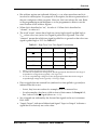
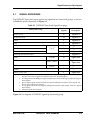
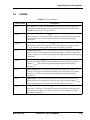
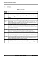
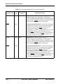
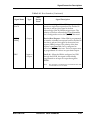
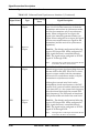
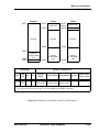
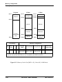
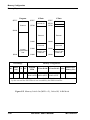
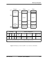
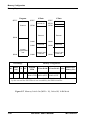
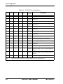
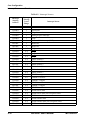
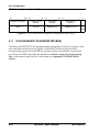
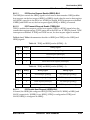
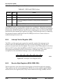
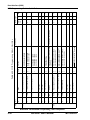
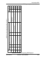
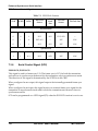
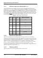
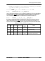
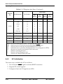
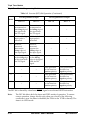
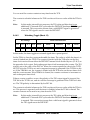
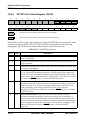
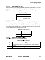
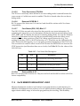
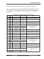
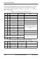
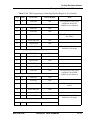
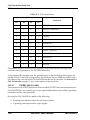
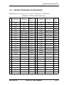
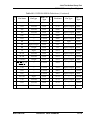
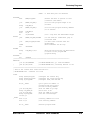
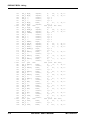
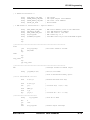
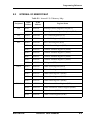
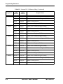
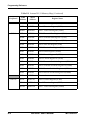
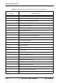
Enhanced Synchronous Serial Interface
ESSI Data and Control Signals
Table 7-1 ESSI Clock Sources
SYN
SCKD
SCD0
RX Clock
Source
RX
Clock
Out
TX Clock
Source
TX Clock Out
Asynchronous
0
0
0
EXT, SC0
—
EXT, SCK
—
0
0
1
INT
SC0
EXT, SCK
—
0
1
0
EXT, SC0
—
INT
SCK
0
1
1
INT
SC0
INT
SCK
Synchronous
1
0
0/1
EXT, SCK
—
EXT, SCK
—
1
1
0/1
INT
SCK
INT
SCK
7.3.6
Serial Control Signal (SC2)
ESSI0:SC02; ESSI1:SC02
This signal is used for frame sync I/O. The frame sync is SC2 for both the transmitter
and receiver in synchronous mode and for the transmitter only in asynchronous mode.
The direction of this signal is determined by the SCD2 bit in the CRB.
When configured as an output, this signal outputs the internally generated frame sync
signal.
When configured as an input, this signal receives an external frame sync signal for the
transmitter in asynchronous mode and for both the transmitter and receiver when in
synchronous mode.
SC2 can be programmed as a GPIO signal (P2) when the ESSI SC2 function is not in use.
7-8
DSP56307 User’s Manual
MOTOROLA