1
Programming Reference
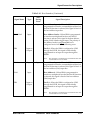
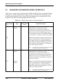
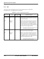
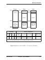
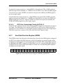
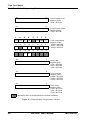
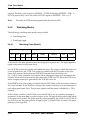
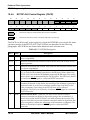
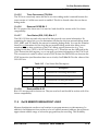
Inverter Bit 8
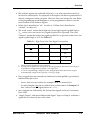
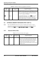
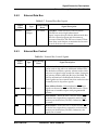
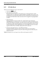
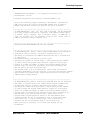
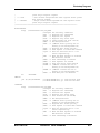
0 = 0- to-1 transitions on TIO input increment the counter,
or high pulse width measured, or high pulse output on TIO
Timers
1 = 1-to-0 transitions on TIO input increment the counter,
or low pulse width measured, or low pulse output on TIO
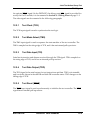
Timer Reload Mode Bit 9
0 = Timer operates as a free
running counter
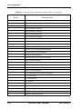
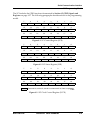
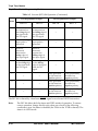
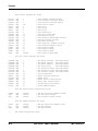
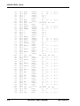
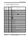
TC (3:0)
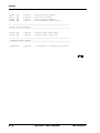
0000
0001
0010
0011
0100
0101
0110
0111
1000
1001
1010
1011
1100
1101
1110
1111
1 = Timer is reloaded when
selected condition occurs
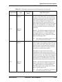
Direction Bit 11
0 = TIO pin is input
1 = TIO pin is output
Data Input Bit 12
0 = Zero read on TIO pin
1 = One read on TIO pin
Data Output Bit 13
0 = Zero written to TIO pin
1 = One written to TIO pin
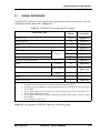
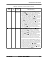
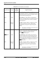
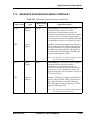
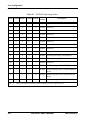
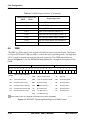
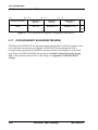
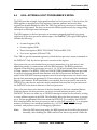
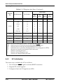
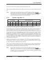
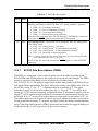
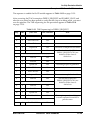
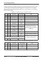
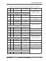
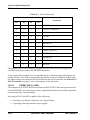
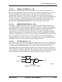
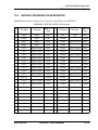
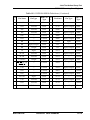
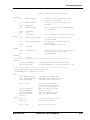
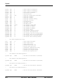
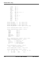
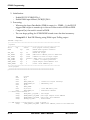
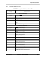
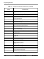
Timer Control Bits 4 – 7 (TC0 – TC3)
TIO
Clock
Mode
GPIO Internal Timer
Output Internal Timer Pulse
Output Internal Timer Toggle
Input External Event Counter
Input
Internal Input Width
Input
Internal Input Period
Input
Internal Capture
Output Internal Pulse Width Modulation
–
–
Reserved
Output Internal Watchdog Pulse
Output Internal Watchdog Toggle
–
–
Reserved
–
–
Reserved
–
–
Reserved
–
–
Reserved
–
–
Reserved
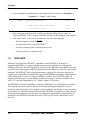
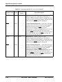
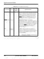
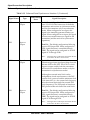
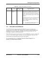
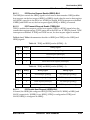
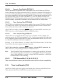
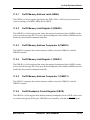
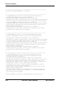
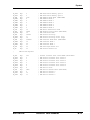
Timer Enable Bit 0
0 = Timer Disabled
1 = Timer Enabled
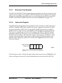
Prescaled Clock Enable Bit 15
0 = Clock source is CLK/2 or TIO
1 = Clock source is prescaler output
Timer Overflow Interrupt Enable Bit 1
0 = Overflow Interrupts Disabled
1 = Overflow Interrupts Enabled
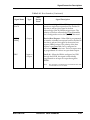
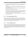
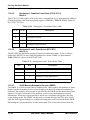
Timer Compare Flag Bit 21
0 = “1” has been written to TCSR(TCF),
or timer compare interrupt serviced
Timer Compare Interrupt Enable Bit 2
0 = Compare Interrupts Disabled
1 = Compare Interrupts Enabled
1 = Timer Compare has occurred
Timer Overflow Flag Bit 20
0 = “1” has been written to TCSR(TOF),
or timer Overflow interrupt serviced
1 = Counter wraparound has occurred
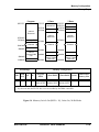
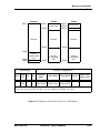
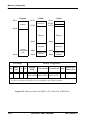
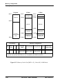
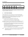
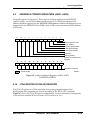
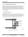
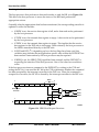
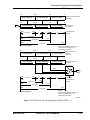
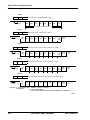
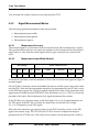
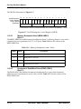
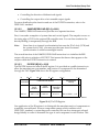
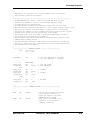
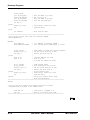
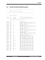
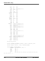
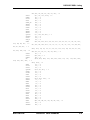
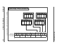
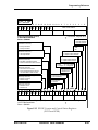
23 22 21 20 19 18 17 16 15 14 13 12 11 10 9
*0 *0
TCF
TOF
*0 *0 *0 *0
PCE
*0
DO
DI
DIR
*0
8
TRM INV
7
6
5
4
3
TC3
TC2
TC1
TC0
*0
Timer Control/Status Register
TCSR0:$FFFF8F Read/Write
TCSR1:$FFFF8B Read/Write
TCSR2:$FFFF87 Read/Write
Reset = $000000
2
1
TCIE TQIE
0
TE
= Reserved, Program as 0
*
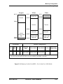
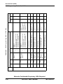
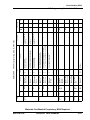
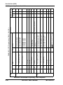
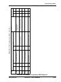
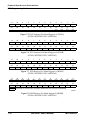
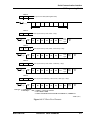
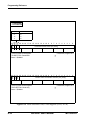
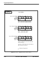
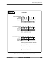
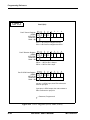
Figure E-19 Timer Control/Status Register (TCSR)
MOTOROLA
DSP56307 User’s Manual
E-35