1
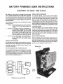
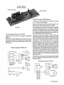
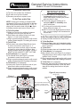
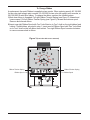
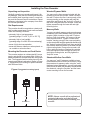
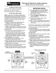
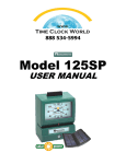
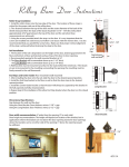
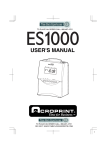
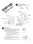
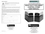
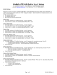
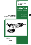
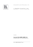
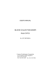
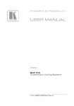
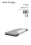
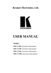
888 534-5994 Model 125BP USER MANUAL General Service Instructions Models 125 and 150 Recorders To Remove Case Cover IMPORTANT NOTES 1) Turn key one quarter turn clockwise. 2) Lift case cover up then forward. 3) Reverse procedure to replace cover. To Set Time and/or Date NOTE: Unless your recorder is equipped with continental (0-23) hours, all PM hours on the time card will be printed underscored (Ex.: 1:00). To change the time and/or date follow these steps: 1) Unplug recorder and remove Case Cover. 2) To Set Day/Date A) Make sure current time setting is between midnight and noon (see note above). B) Push down and release Yellow Lever (see Figure 1) to set correct day/date. C) Plug in recorder and punch card to verify correct setting. Repeat steps A-C if reading is incorrect 3) To Set Time A) Push down and release Black Minute Lever to set the correct time (see Figure 1). If minute lever does not work, plug in recorder and wait for minute hand to advance, then unplug recorder and try lever again. DO NOT MOVE CLOCK HANDS TO SET THE TIME. 4) To Set Month (if so equipped) A) Turn Month Knob (see Figure 1) counterclockwise to select correct month. B) Plug in recorder and punch card to verify correct setting. Repeat steps A-B if reading is incorrect. 5) To Set Year (if so equipped) A) Insert point of pen into spoke on side of year wheel and rotate counter-clockwise. B) Plug in recorder and punch card to verify correct setting. Repeat steps A-B if reading is incorrect. 1) The date setting (if so equipped) MUST be manually reset to the first of the month each month, following any month with less than 31 days. 2) The month and year settings (if so equipped) MUST be manually reset every month/year. 3) To reset your recorder after a power failure follow the steps 1-5. 4) HINT: If clock is set slightly ahead of actual time, you may unplug it until it matches the correct time. To Set Time and/or Date for Left Print Models 1) Unplug recorder and remove Case Cover. 2) To Set Day/Date A) Follow the same steps as for standard models, but note the different location of Yellow Day/Date lever in Figure 2. 3) To Set Time A) Follow the same steps as for standard models. 4) To Set Month (if so equipped) A) Move Month Lever (see Figure 2) to extreme left position then return slowly to right until an audible "click" is heard. B) Plug in recorder and punch card to verify correct setting. Repeat steps A-B if reading is incorrect. 5) To Set Year (if so equipped) A) Note that year set lever is located at the rear of the typehead assembly. Follow the same steps as for setting the month on left print models. Figure 2 (left print models) Month Lever Figure 1 Black Minute Lever (cover removed) I0 II I2 I 2 3 9 8 Black Minute Lever C R OP R I N T 7 6 5 4 RALEIGH, N.C. USA Note: Day/Date & Month levers are shown in cut-away views. The levers are behind the clock dial. Yellow Day/Date Lever Month Knob (turn counter-clockwise) Yellow Day/Date Lever I0 II I2 I 2 3 9 8 C R OP R I N T 7 6 5 4 RALEIGH, N.C. USA To Change Ribbon A replacement Acroprint Ribbon is supplied on two spools. When ordering specify 20-106-002 for two-color right margin print recorder, 20-106-000 for two-color left margin print recorder, or 20-0106-003 for solid blue ribbon. To replace the ribbon, perform the following steps. 1) Note how ribbon is threaded. Pull right Ribbon Tension Spring (see Figure 3) forward and remove spool. Pull left Ribbon Tension Spring (see Figure 3) forward and remove spool. Remove and discard ribbon. 2) Insert new right Ribbon Spool with "hex" hole fitted on to "hex" shaft on the right ribbon feed ratchet. Thread ribbon, as noted in step 1. Insert new left Ribbon Spool with "hex" hole fitted on to "hex" shaft on the left ribbon feed ratchet. Turn right Ribbon Spool counter-clockwise to remove excess slack in ribbon. Figure 3 (front view with cover removed) I0 II I2 I 2 3 9 8 Ribbon Tension Spring Ribbon Spool C R OP R I N T 7 6 5 4 RALEIGH, N.C. USA Ribbon Tension Spring Ribbon Spool Installing the Time Recorder Unpacking and Inspection Wooden/Plywood Walls Carefully unpack your recorder and inspect it for any damage. Verify that the following accessories are included: three mounting screws, a case lock key, and the General Service Instructions. Report damage or shortages to the company from which the unit was purchased. You may use the three screws included with the recorder to mount the recorder. Install a screw in the wall 53" above the floor. Leave enough of the screw protruding so the recorder will hang flat against the wall through the "keyhole" on back of the clock. Hang and level the recorder. Insert and tighten screws through the lower left and right mounting holes. Site Requirements The recorder should be mounted on a sturdy wall, shelf, or other support area. Do not use the recorder under the following conditions: extremely high or low temperature [operating range: 0° to 50° C (32° to 122° F)] extremely high or low humidity [operating range: 0 to 90% RH non-condensing] areas of high dust concentration areas with extreme vibration or when placed on an unstable or unlevel surface Mounting the Recorder and Card Racks The recorder requires an uninterrupted AC power supply, and should be mounted within 6 feet of a power receptacle to accommodate the unit's power cord. The suggested wall mounting layout for the recorder and optional card racks is shown in Figure 4. Suggestions for mounting on specific wall and shelf surfaces follow. Figure 4 (suggested mounting layout) 45" 32" 40" RECEPTACLE Masonry Walls You may use plastic masonry anchors and screws available at your local hardware store to mount the recorder. Mark a location on the wall 53" above the floor. Drill a hole with a 1/4" masonry bit and insert a plastic anchor. Tighten a screw at this location, leaving enough of the screw protruding so the recorder will hang flat against the wall through the "keyhole" on back of the clock. Hang and level the recorder. Mark the location of the lower left and right mounting holes. Remove the recorder, drill holes, and insert anchors. Replace the recorder, insert and tighten screws through the lower left and right mounting holes, and fully tighten the "keyhole" screw. Sheetrock/Hollow Core Walls You may use "molly" fasteners available at your local hardware store to mount the recorder. Follow the procedure for masonry walls, using the "molly" fasteners instead. Alternatively, you may use longer wood screws to attach the recorder to a stud behind the sheetrock, using the "keyhole" and the lower center mounting hole on the recorder. NOTE: Always consult with a professional contractor/carpenter and obey all local building and fire codes when installing your recorder.