1
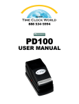
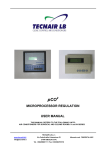
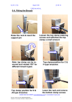
GENERAL INFORMATION
CAUTION: For your safety and to prevent damage to the machine, we recommend that you remove the line cord from the wall receptacle when setting or
replacing the ribbon.
For repairs, please contact your authorized Acroprint dealer.
MAINTENANCE
To obtain the best results from your Electric Stamp, we recommend periodic inspections, cleaning,
and lubrication each year by an authorized dealer. For further information contact your dealer or
Acroprint Time Recorder.
NOTE: This equipment has been tested and found to comply with the limits for a Class A digital
device, pursuant to Part 15 of the FCC Rules. These limits are designed to provide reasonable
protection against harmful interference when the equipment is operated in a commercial
environment. This equipment generates, uses, and can radiate radio frequency energy and, if not
installed and used in accordance with the instruction manual, may cause harmful interference
to radio communications. Operation of this equipment in a residential area is likely to cause
harmful interference in which case the user will be required to correct the interference at his own
expense.
MACHINE REFERENCE
Date Purchased __________________________________________________________
Model No. _____________________________ Serial No. _________________________
Key No. ______________________
Dealer _________________________________________________________________
Address ________________________________________________________________
City _____________________________ State ____________ Zip __________________
Phone No. ____________________________________
5-23 50th Avenue
Long Island City, NY 11101
718.784.4900
Fax: 718.472.9491
Email: [email protected]
www.centraltimeclock.com
HEAVY-DUTY DOCUMENT
CONTROL STAMP
USER MANUAL
INTRODUCTION
We thank you for purchasing an
Acroprint Heavy Duty Document
Control Stamp. Packaged with your
machine are:
• two (2) Keys.
• one (1) User’s Manual and the
Warranty Card.
FIGURE 2
Depress to
Raise
Ribbon
Feeler
Please complete the warranty card
and return the tear-off portion to the
factory as soon as possible. The model
and serial numbers are displayed
on the label located on the back of
the machine. The serial number is
a seven digit number followed by
two alphabetic characters (example:
1234567AH).
Ribbon
Drive Shaft
Apply pressure
We suggest you record the above
information in the information
reference section on the back page,
making sure to list your key number.
Before operating your Acroprint Heavy
Duty Document Control Stamp, please
read these instructions completely. For
optimum performance, do not plug
stamp into an electrical circuit with
other office machines or appliances. Caution should be used when
stamping forms with paper clips or
staples attached. Serious damage
to the print mechanism and/or
the electronic circuit could result.
Service should be limited to qualified
technicians only.
Ribbon
Tension
Spring
FIGURE 8
Cover
Lock
Levers
Typehead
Assembly
FIGURE 1
Lower
Housing
To Remove Slack
FIGURE
FIGURE 98
Upper Tie Bar
Pivot Ribbon Drive Assembly
Upward or Downward
FIGURE 3
FIGURE 6
Typewheels
CAUTION:
Be sure the machine is disconnected
from the wall outlet when setting
typewheels.
SETTING
The stamp has a typehead with 6 or more
typewheels which print information such as
year, month, date, etc. It is necessary to set each
typewheel prior to using your new machine.
Mounting
Slot
Open Cover
• Insert key.
• Turn key clockwise and tilt cover upward.
Front Support Pin
Rear Pivot Pin
Open Typehead
• Push down on the 2 lock levers, at the same
time pull up on the typehead (See Figure 2).
Lower Housing
Upper Tie Bar
Depress to Raise
Ribbon Feelers
FIGURE 4
Model Notes:
Time/Date Stamps (ET and ETC) – After
setting, the machine will keep the time and
date automatically. The month typewheel
must be manually changed and the date
reset each month. The year typewheel must
be manually changed each year.
Front Ribbon
Feeler
Rear Ribbon Feeler
Ribbon
Setting Typewheels
•Set the typewheels by pushing the Ratchet
on the side of the typewheel down (See
Figure 4). Make sure the typewheel seats
correctly; you will hear a distinct click when
the typewheel seats.
Date Stamps (ED) – The date typewheels
must be set each day.
Typewheels
Ribbon Tension
Springs
Front Mounting
Slot
FIGURE 7
Rear Mounting
Slot
Advance Typewheel Ratchet
with Pointed Object
Numbering Machines (EN, END, EDN) – The
first 6 typewheels advance automatically after
each punch. Any additional wheels (including
date) must be manually changed.
RIBBON REMOVAL/INSTALLATION
When the printing becomes light, change the ribbon. Using other
than authorized Acroprint ribbons may result in the ribbon not
advancing or reversing properly.
ADJUSTABLE PRINT IMPACT CONTROL
The Stamp has an adjustable Print
Impact Control (see Figure 5).
• Turning the knob clockwise increases the impact, turning the knob
counterclockwise lowers the impact.
Warning
Be careful when changing the ribbon.
Ribbon ink will stain your hands and clothes.
The standard setting is midway between soft and hard. Use the
lowest setting that provides a clear imprint. Replacing worn ribbons
instead of increasing the print impact will extend the machine’s
lifespan.
1 Unplug machine.
2 Open cover and typehead .
(see Setting for instructions)
3 Grasp the Ribbon mechanism upper tie bar and pull upwards
and then out.
4 Place the ribbon mechanism on a sheet of paper with the
ribbon facing down.
5 Depress and hold down the front ribbon feeler lever. Push the
back of the spool towards you until it clears the ribbon drive
shaft, then pull the spool off of the ribbon tension spring.
(See Figure 8)
6 Repeat step 5 to remove the rear ribbon spool.
7 Place the new ribbon on a piece of paper with the spools about
6” apart and the empty spool at the front.
8 Place the ribbon drive mechanism over the ribbon.
9 Starting at the rear, pull the ribbon through the center and over
the lower tie bar. Depress and hold down the rear ribbon feeler
lever, with your other hand place the new spool on the stud on
the ribbon tension spring. Apply pressure to the spool/spring,
pivot the spool and mount the spool onto the ribbon drive
shaft. Note: Rotate the spool to make sure it seats fully.
DIGITAL CLOCK - SETTING CONTROLS - ETC Model Only
The ETC model is equipped with a digital clock. You will find the
setting controls beside the Print Impact Control Knob located in the
lower housing of the machine. (See Figure 5). Each control is labeled
with letters and operates as follows.
Setting Function
Command
Hour Set:
Minute Set:
Depress “H” switch
Depress “M” switch
Setting Digital Display (ETC)
The digital display must be set to match the typewheels.
• Plug in machine.
• Press the H (Hour) button to advance
the hour.
• Press the M (Minute) button to advance the minute.
• When you hear the minute advance
click, take a print.
• Match the display to the printed time.
Close Typehead
• Lower the typehead.
• Press down and insure that both lock levers latch and typehead is
secure.
Warning: Be careful when
changing the ribbon not to get
ink on your clothing. The ink
Close Cover
• Lower the cover until it latches into the typehead assembly.
will not wash out of clothing.
Digital Clock
Controls
FIGURE 5
Adjustable
Print Impact
Control Knob
H M
Soft
Hard
10 R
epeat step 9 to install the other spool on the front.
11 Remove ribbon slack by turning the
front spool in the direction the arrow illustrates (See Figure 9).
The ribbon is ready to be reinstalled.
12 Grasp the upper tie bar of the ribbon mechanism. Slide the rear
mounting slot into the rear pivot pin (See Figures 6 & 7). Then
pivot the ribbon mechanism down into front support pin slot.
13 Lower the typehead.
14 Close the cover.
15 Plug in machine and take a test print.