1
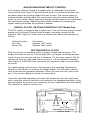
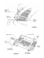
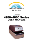
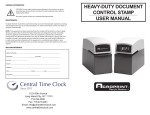
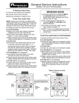
USER’S MANUAL
For
Acroprint’s Heavy-Duty
Document Control Stamps
INTRODUCTION
We thank you for purchasing an Acroprint Electric Stamp. Packaged with your
machine are two (2) Keys, one (1) User’s Manual and the Warranty Card.
Please complete the warranty card and return the tear-off portion to the factory
as soon as possible. The model and serial numbers are displayed on the label
located on the back of the machine. The serial number is a seven digit number
followed by two alphabetic characters (example: 1234567AH).
We suggest you record the above information in the information reference
section on the back page, making sure to list your key number.
Before operating your Acroprint Electric Stamp, please read these instructions
completely. For optimum performance, do not plug stamp into an electrical
circuit with other office machines or appliances. Caution should be used
when stamping forms with paper clips or staples attached. Serious damage
to the print mechanism and/or the electronic circuit could result. Service
should be limited to qualified technicians only.
FIGURE 1
Cover
Release Pin
Typehead Assembly
Lower Housing
Typewheels
Release Pin
FIGURE 2
SETTING THE TYPEWHEELS
Your Acroprint stamp is equipped with a typehead consisting of six or more
typewheels which print specific information such as year, month, date, etc. It is
necessary to set each typewheel to the desired position prior to operating the
machine.
CAUTION: Be sure the machine is disconnected from the wall outlet
when setting typewheels.
To set the typewheels, insert the key into the lock and turn it clockwise. Tilt the
cover upward. Pull the release pin from the right-hand side to remove it. Lift the
typehead assembly. (See Figure 2) Set each typewheel to the desired character
by pushing the typewheel RATCHET beside each typewheel in a downward
direction with a pointed object such as a ball point pen. (See Figure 3) Make
sure the typewheel ratchet is correctly seated. You will hear a distinct click when
it is rotated into place. Lower the typehead assembly; insert the release pin from
the right-hand side. Lower the cover so that the cover latches to the typehead
assembly. Plug the unit in and insert a piece of paper into the throat until the
stamp prints to verify the registration. The machine is now ready for normal use.
TIME/DATE STAMPS (Models ET and ETC) — After setting the typehead the
machine will automatically rotate the wheels. It will be necessary for you to
manually change the month wheel each month, reset the date wheels each
month, and advance the year wheels on the first day of each year.
DATE STAMPS (Model ED) — It will be necessary for you to manually reset the
date wheels daily.
NUMBERING MACHINES (Models
EN, END, and EDN) — The first six
typewheels will advance automatically after each registration. All
additional number wheels must be
manually changed. If your numbering machine is equipped with a date
section, the date wheels must be
manually reset daily.
FIGURE 3
ADJUSTABLE PRINT IMPACT CONTROL
Your Acroprint Electric Stamp is equipped with an adjustable Print Impact
Control Knob (See Figure 4). By turning this knob in a clockwise direction you
can easily adjust the printing impact from soft to hard. The normal setting is
midway between soft and hard. We recommend using the softest setting that
works for your needs. When imprinting through several carbons we recommend
the hard impact setting. Replacing worn ribbons instead of increasing the
impact setting will extend the machine’s lifespan.
DIGITAL CLOCK - SETTING CONTROLS - ETC Model Only
The ETC model is equipped with a digital clock. You will find the setting controls
beside the Print Impact Control Knob located in the lower housing of the
machine. (See Figure 4). Each control is labeled with letters and operates as
follows.
Setting Function
Command
Hour Set:
Minute Set:
Depress “HR” switch
Depress “MN” switch
SETTING DIGITAL CLOCK
Plug the unit into an electrical outlet of proper voltage and frequency. The
display will flash on and off. This will stop when you begin the setting process.
Insert the key into the lock and turn it clockwise. Tilt the cover upward. Pull the
release pin from the right-hand side to remove it. Lift the typehead assembly.
(See Figure 2) CAUTION: Use care when the machine is open to avoid electrical shock.
The digital display must be set to correspond to the typehead. Depress the
Minute or Hour Button to advance the digital display. You will hear a distinct
click as the minute typewheel advances. When you hear the click, take a test
print. Then set the display to match the time printed.
Lower the typehead assembly and insert the release pin from the right-hand
side. Lower the cover so that the cover latches to the typehead assembly. Verify
synchronization by printing and comparing the print registration with the display.
The machine is ready for normal use.
Digital Clock Controls
HR MN
Soft
FIGURE 4
Hard
Adjustable Print Impact
Control Knob
RIBBON REMOVAL/INSTALLATION
Your Acroprint machine is equipped with a new printing ribbon. When the
printing registrations become so light that they are unreadable, it is necessary to
change the ribbon. Using other than authorized Acroprint ribbons may result
in the ribbon not advancing or reversing properly. Proceed as follows:
1.
2.
3.
4.
Unplug machine from electrical outlet.
Insert the key into the lock and turn it clockwise. Tilt the cover upward. Pull
the release pin from the right-hand side to remove it. Lift the typehead
assembly. (See Figure 2)
Grasp the upper tie bar on the ribbon drive mechanism and pull upwards
and then out away from the machine. (See Figure 5)
Place the ribbon drive mechanism on a sheet of paper with the ribbon
facing down. (See Figure 6) NOTE: It is necessary to remove the ribbon
spools one at a time.
Warning: Be careful when changing the
ribbon not to get ink on your clothing. The
ink will not wash out of clothing.
Cover
Upper Tie Bar
Ribbon Drive Assembly
Pivot Ribbon Drive
Assembly Upward or
Downward
Mounting Slot
Front Support Pin
Rear Pivot Pin
Lower Housing
FIGURE 5
5.
Start with the front spool of the assembly; depress and hold down the
ribbon feeler lever. This allows the spool to turn freely. Push the back of the
spool towards you until it is clear of the ribbon drive shaft, then pull the front
of the spool off of the ribbon tension spring. (See Figure 7)
6. Repeat step 5 to remove the rear ribbon spool. Discard the old ribbon.
7. Place the new ribbon on a piece of paper with the spools about 6" apart.
Place ribbon drive mechanism over the ribbon.
8. Starting with the rear spool, depress and hold down the rear ribbon feeler
lever. With your other hand, slide the new spool onto the stud mounted on
the ribbon tension spring. Apply pressure to the spring/spool and pivot the
spool allowing the other end to be mounted onto the ribbon drive shaft.
(See Figure 7) NOTE: Rotate the spool (with the ribbon feeler lever
depressed) slightly to correctly seat the ribbon drive shaft, if necessary.
9. Repeat Step #8 to install the other ribbon spool.
10. Remove all ribbon slack by turning either the front or rear ribbon drive
ratchet in the direction the arrow illustrates (See Figure 8) until the ribbon is
snug against the lower tie bars. The ribbon drive mechanism is now ready
to be installed on the machine.
11. Grasp the upper tie bar of the ribbon drive mechanism so that the rear
mounting slot is pointing away from you. Slide the rear mounting slot into
the rear pivot pin located on the left side of the lower housing. (See Figures
5 & 6) Then pivot the ribbon drive mechanism downward into place.
12. Lower the typehead assembly, insert the release pin from the right-hand
side. Lower the cover so that the cover latches to the typehead assembly.
Plug the unit in and insert a piece of paper into the throat until the stamp
prints. The machine is now ready for normal use.
FIGURE 6
FIGURE 7
FIGURE 8
GENERAL INFORMATION
CAUTION: For your safety and to prevent damage to the machine, we
recommend that you remove the line cord from the wall receptacle when
setting or replacing the ribbon.
For repairs, please contact your authorized Acroprint dealer.
MAINTENANCE
To obtain the best results from your Electric Stamp, we recommend periodic inspections,
cleaning, and lubrication each year by an authorized dealer. For further information
contact your dealer or Acroprint Time Recorder.
MACHINE REFERENCE
Date Purchased __________________________________________________________
Model No. _____________________________ Serial No. _________________________
Key No. ______________________
Dealer _________________________________________________________________
Address ________________________________________________________________
City _____________________________ State ____________ Zip __________________
Phone No. ____________________________________
5640 Departure Drive
Raleigh, NC 27616-1841 USA
IN USA 800.334.7190
919.872.5800
www.acroprint.com
06-0103-001 Rev J