Transcript
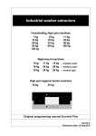
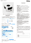
ELECTRIC FAN
PART FIGURE
CAUTION
Fig. 1
Read Rules for Safe Operation and Instructions Carefully.
Front Guard
Blade
WARNING
OWNER’S MANUAL
STAND FAN
MODEL:FS40-12AR
Please read the instruction manual carefully before use and safekeeping.
1. If the supply cord is damaged, it must be replaced by manufacturer
or its service agent or a similarly qualified person in order to avoid
a hazard.
2. To protect against the risk of electrical shock, do not immerse the
unit, cord or plug in water or other liquid.
3. This appliance is not intended for use by persons (including
children) with reduced physical, sensory or mental capabilities, or
lack of experience and knowledge, unless they have been given
supervision or instruction concerning use of the appliance by a
person responsible for their safety. Young children should be
supervised to ensure that they do not play with the appliance.
4. When the appliance is not in use and before cleaning, unplug the
appliance from the outlet.
5. Keep electrical appliances out of reach from Children or infirm
persons. Do not let them use the appliances without supervision.
6. When the fan was assembled, the rotor blade guard shall not be
taken off anymore
- Prior cleaning unplug the fan.
- The rotor guard shall not be dissembled/opened to clean the
rotor blades.
- Wipe the fan enclosure and rotor blade guard with a slightly
damp cloth.
RULES FOR SAFE OPERATION
1. Never insert fingers, pencils, or any other object through the grille when fan is
running.
2. Disconnect fan when moving from one location to another.
3. Be sure fan is on a stable surface when operating to avoid overturning.
4. DO NOT use fan in window, rain may create electrical hazard.
5. Household use only.
MIDEA.COM | 4008899315
1
Fig. 2
Straight face
Rear Guard
Shaft
OPERATING INSTRUCTIONS
Plug in the power adapter, after a "beep" tone, the fan is on standby.
I. Remote Controller (Fig.7)
Hook hole
Hook
Motor
“
” ON/OFF KEY
Press this button under standby mode, the fan starts at normal wind of level 10, then
the panel displays "normal wind, level 10". Press this button during working, the fan
turns off to standby mode.
After start, rotate the drive plate clockwise, the fan increases from the current level
circulation in the following manner: standard mode 01 to wind 26→ stimulating
natural mode 00→ sleep mode 00 → intelligent mode
00 → silent mode
01 to wind 09. Rotate the drive plate counterclockwise, the fan will decrease from
the current level in the above manner.
Inner tube
Opening
Center Piece
Circlip
Fan Box
Clip
Plastic Nut
Control Part
Remote Control Hook
Tighten
Loosen
Spinner
Female Terminal
Fastening Screw
Fastening Knob
Round Base
Tube
Butterfly Screws For
Fixed Base Tube
Note: All the pictures in this manual are for explanation purpose only. Any discrepancy between
the real object and the illustration in the drawing shall be subject to the real subject.
GUARD & FAN BLADE ASSEMBLY
1. Unscrew and remove the spinner clockwise (or obtain from parts bag), and the
plastic nut counterclockwise. You may have to hold the shaft in place with one
hand to unscrew the spinner with the other. Position the rear guard against the
motor face so that the two pins on the motor face fit through the matching holes
in the rear guard. Tighten the rear guard into place with the plastic nut. (Fig.3)
2. Mount the blade set onto the motor shaft through the center hole in the blade
set. Insert the pin on the motor shaft into the notches on the back of the blade
set. Turn the spinner counterclockwise onto the shaft to tighten the blade set
into place. (Fig.4)
3. Remove the small screw from the clear plastic clasp on the bottom of the front
guard and set aside. Place the front guard over the rear guard so that the tab
at the top of the front guard fits over the rear guard rim (Fig.5). Push the two
guards together. Close the clasp at the front guard bottom over the rear guard
rim, and re-insert and tighten the small screw (Fig.6) removed earlier.
“
” OSC KEY
After the fan starts, repeatedly touch this button to start or stop oscillation.
ASSEMBLY INSTRUCTION
1. Take out the base tube, three butterfly screws for fixed base tube and the round
base from the packing carton;
2. Insert the tube to the round base, be sure to make the positioning screw align
with the base;
3. Screw and tighten the three butterfly screws into the holes on the tube;
4. Loosen the fastening knob, adjust the height of inner tube and tighten the knob.
5. Take out the control part of the fan from the packing carton, loosen the fastening
screw at the back of the box, insert the inner tube into the bottom hole, make sure
that the fastening screw and the fastening knob in the same position.
6. Usage of the remote control hook: make the straight face of hook up, clip the hook
to the inner tube along with the opening, the hook can be moved up and down
along the tube (Fig.1). The hook of the remote control may be linked to the
hole for storage when not in use. (Fig.2)
2
“
” MODE KEY
Repeat press this button, the wind will be switched in order of “standard mode stimulating natural mode - sleep mode - intelligent mode - standard mode ... ".
Standard mode : the wind speed is constant set by the wind level, when the
"standard mode" icon is lit, 01 - 26 levels are standard mode;
Stimulating natural mode : Fan will simulate natural wind according to
preprogrammed manner, the wind speed changes in accordance with the program,
which makes people feeling idle, naturally and it likes to be in the nature.
Intelligent mode
:based on the temperature and wind speed when it starts, its
speed changes according to the temperature. When the temperature is below 20°C,
the fan stops, when the temperature rises to 20°C, it continues automatically at the
stopped level.
Silent mode : fan blows in silent mode; it has a total of nine levels for adjustment.
Sleep mode : fan blows in sleep mode; it is sultable for sleep.
screw
Fig.3
Fig.4
Fig.5
Blade Set
Fig.7
Fig.8
Remote controller
Battery
Battery cover
On/Off
Drive plate
OSC
Fig.6
PRO/Timer
Mode
3
“
” PRO KEY
Under power-on state, timed power-off can be set. Press the PRO button; it starts the
timing power-off state.
icon displayed on the fan display will flash once
per second, the rotate the drive plate clockwise, the fan display will display 0.5 → 1.0
→ ...... → 7.5 → 8.0 → 00 → 0.5 → ...... in cycle, rotate the drive plate counterclockwise, it cycles as 8.0 → 7.5 → ...... → 0.5 → 0 0 → 8.0 → .......
When set a time, 5 seconds without any operation, the timing on the display flashes
twice and beep to refer successfully settings, if the timing button is pressed in five
seconds then timing is cancelled. If there is time setting, then
icon is lit, if not, it is
off. When setup is successful, the display returns to display the wind level.
Under power-off mode, press the PRO button to set power-on time, "PRO" and icon
is lit, the operation mode will refer to timed power-off; rotate the drive plate to
adjust the time. After adjustment, the set time will be displayed on the screen. To
cancel a time setting, only need to press the PRO button once again.
4
Inquiry: Under working state, press forward/timing button to enter the timing status,
user can check the set time, and user can re-set the time within five seconds; if no
operation within five seconds, the time shown on the screen flashes twice and
returned to the wind level.
II. Control Panel (Fig.9)
• On/Off button
Same as them on remote control.
• Function button
1. Under working state, short press the function
button, the fan will alternate between oscillation
and fix; Long press the button, the fan enters
into the timing function, refer to the operating
instructions of PRO button on remote control
(To cancel the timer, long press function button).
2. Under standby mode, short press of the function
button is invalid; Long press the function button,
the fan enters into the appointment starting
function, refer to the operating instructions of
PRO button on remote control (To cancel the
timer, long press function button).
III. Tilt Adjustment
To adjust the air flow upward or downward, push
the guards lightly to the desired direction.
Fig.9
Batteries should be installed before using the remote control. It uses a 3 -volt button
battery.
(1) Open the battery cover;
(2) install a new battery, pay attention to the battery polarity (+ and -);
(3) Close the battery cover.
HOW TO USE THE REMOTE CONTROLLER CORRECTLY
1. The remoter controller must point to the receiving window of the fan box when it
is used;
2. The remoter controller can be normally used within five meters and 30 degrees
from the fan;
3. Avoid direct sunlight on the receiving window, so as not to affect the receiver's
effect;
4. Remove the built-in batteries when do not use the remote control for a long time
or before the batteries are leaked.
OVERHEAT PROTECTION OF THE MOTOR
On/Off button
Function button
IV. Height Adjustment
Lowing: lift up the head with a hand, unscrew the fastening knob counterclockwise
with the other hand, slowly lower the head to an appropriate height, and tighten the
knob clockwise. Rising: lift up the head with a hand, unscrew the fastening knob
counterclockwise slowly with the other hand, rises up the head to a proper height,
and tighten the knob clockwise.
V. Pivoting Angle Adjustment
When adjust the pivoting angle, fix the guards with hands and reverse the head of fan.
Note: Do not forcibly twist the fan in order to avoid damage to the fan.
VI. Screen-off Function
Press the “On/Off" button for three seconds, the screen will turn off and the fan is still
running. Press any button [not include "On/Off” button), the screen will light up.
Remote control does not have this feature.
VII. Forced Shutdown
The fan will be turned off when there is no operation of the control within 12 hours.
5
BATTERIES INSTRUCTIONS (Fig.8)
The windings of the motor have a thermal-fuse that burns out and the fan switches
off and temperature of the motor is no longer going up so that plastic parts of the fan
don’t subject to deformation so far so to be burned by the overheat if the motor is
overheat for any unexpected reason.
MAINTENANCE INSTRUCTION
The fan requires little maintenance. Do not try to fix it by yourself. Refer it to
qualified service personnel if service is needed.
1. Before cleaning and assembling, fan must be unplugged.
2. To ensure adequate air circulation to the motor, keep vents at the rear of the
motor free of dust. Do not disassemble the fan to remove dust.
3. Please wipe the exterior parts with a soft cloth soaking a mild detergent.
4. Do not use any abrasive detergent or solvents to avoid scratching the surface.
Do not use any of the following as a cleaner: gasoline, thinner.
5. Do not allow water or any other liquid into the motor housing or interior parts.
CLEANING
1. Be sure to unplug from the electrical supply source before cleaning.
2. Plastic parts should be cleaned with a soft cloth moisten with mild soap.
Thoroughly remove soap film with dry cloth.
6
GD Midea Environment Appliances Manufacturing CO.,LTD.
Midea Industrial Park, Dongfu Road, Dongfeng Town, Zhongshan, Guangdong, China